Documentation - Berker
Documentation - Berker
Documentation - Berker

Create successful ePaper yourself
Turn your PDF publications into a flip-book with our unique Google optimized e-Paper software.
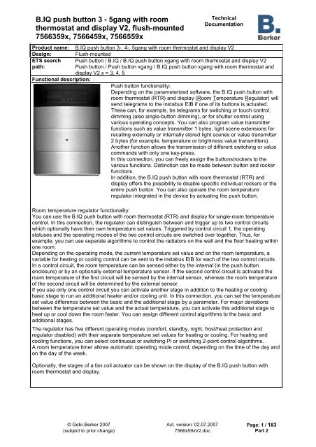
B.IQ push button 3 - 5gang with room<br />
thermostat and display V2, flush-mounted<br />
7566359x, 7566459x, 7566559x<br />
Technical<br />
<strong>Documentation</strong><br />
Product name: B.IQ push button 3-, 4-, 5gang with room thermostat and display V2<br />
Design: Flush-mounted<br />
ETS search Push button / B.IQ / B.IQ push button xgang with room thermostat and display V2<br />
path:<br />
Push button / Push button xgang / B.IQ push button xgang with room thermostat and<br />
display V2 x = 3, 4, 5<br />
Functional description:<br />
Push button functionality:<br />
Depending on the parameterized software, the B.IQ push button with<br />
room thermostat (RTR) and display (Room Temperature Regulator) will<br />
send telegrams to the instabus EIB if one of its buttons is actuated.<br />
These can, for example, be telegrams for switching or touch control,<br />
dimming (also single-button dimming), or for shutter control using<br />
various operating concepts. You can also program value transmitter<br />
functions such as value transmitter 1 bytes, light scene extensions for<br />
recalling externally or internally stored light scenes or value transmitter<br />
2 bytes (for example, temperature or brightness value transmitters).<br />
Another function allows the transmission of different switching or value<br />
commands with only one key-press.<br />
In this connection, you can freely assign the buttons/rockers to the<br />
various functions. Distinction can be made between button and rocker<br />
functions.<br />
In addition, the B.IQ push button with room thermostat (RTR) and<br />
display offers the possibility to disable specific individual rockers or the<br />
entire push button. You can also operate the room temperature<br />
regulator integrated in the device by actuating the push button.<br />
Room temperature regulator functionality:<br />
You can use the B.IQ push button with room thermostat (RTR) and display for single-room temperature<br />
control. In this connection, the regulator can distinguish between and trigger up to two control circuits<br />
which optionally have their own temperature set values. Triggered by control circuit 1, the operating<br />
statuses and the operating modes of the two control circuits are switched over together. Thus, for<br />
example, you can use separate algorithms to control the radiators on the wall and the floor heating within<br />
one room.<br />
Depending on the operating mode, the current temperature set value and on the room temperature, a<br />
variable for heating or cooling control can be sent to the instabus EIB for each of the two control circuits.<br />
In a control circuit, the room temperature can be sensed either by the internal (in the push button<br />
enclosure) or by an optionally external temperature sensor. If the second control circuit is activated the<br />
room temperature of the first circuit will be sensed by the internal sensor, whereas the room temperature<br />
of the second circuit will be determined by the external sensor.<br />
If you use only one control circuit you can activate another stage in addition to the heating or cooling<br />
basic stage to run an additional heater and/or cooling unit. In this connection, you can set the temperature<br />
set value difference between the basic and the additional stage by a parameter. For major deviations<br />
between the temperature set value and the actual temperature, you can activate this additional stage to<br />
heat up or cool down the room faster. You can assign different control algorithms to the basic and<br />
additional stages.<br />
The regulator has five different operating modes (comfort, standby, night, frost/heat protection and<br />
regulator disabled) with their separate temperature set values for heating or cooling. For heating and<br />
cooling functions, you can select continuous or switching PI or switching 2-point control algorithms.<br />
A room temperature timer allows automatic operating mode control, depending on the time of the day and<br />
on the day of the week.<br />
Optionally, the stages of a fan coil actuator can be shown on the display of the B.IQ push button with<br />
room thermostat and display.<br />
© Gebr.<strong>Berker</strong> 2007 Act. version: 02.07.2007 Page: 1 / 183<br />
(subject to prior change) 7566x59xV2.doc Part 2
B.IQ push button 3 - 5gang with room<br />
thermostat and display V2, flush-mounted<br />
7566359x, 7566459x, 7566559x<br />
Functional description (continued):<br />
Technical<br />
<strong>Documentation</strong><br />
Controller extension functions:<br />
Alternatively to its function as a room temperature regulator, the push button RTR can act as a controller<br />
extension. In this manner it can adequately control and operate via its keys or rockers one or several<br />
push buttons RTR which operate as controllers via KNX / EIB communication objects. The display of the<br />
controller extension can also be controlled via objects so that, among other things, the current<br />
temperature values and the active operating modes will also be displayed on all extensions.<br />
Scene function:<br />
The push button RTR can be programmed for up to 8 different scenes. Each scene can control up to 8<br />
different scene objects via switching, value or shutter commands. The scene recall or the storing of new<br />
scene values takes place via an extension object or via touch control.<br />
General functions:<br />
Two independent 1-bit or 1-byte timer functions with up to 14 different switching time events permit the<br />
time-dependent transmission of commands to the bus.<br />
If desired, you can activate a push button assistance function. In this connection, when you actuate a key<br />
its function can be briefly read on the display.<br />
The display of a 14-byte text message (e. g. alarm message) received via the bus, or the display of up to<br />
three pre-parameterized text messages (triggered through 1-bit communication objects), is also possible.<br />
The display background light can be optionally switched through a separate object.<br />
If the B.IQ push button RTC is pulled off the bus coupling unit an alarm message (of 1-bit, 1-byte or of 2byte<br />
type) can be sent.<br />
© Gebr.<strong>Berker</strong> 2007 Act. version: 02.07.2007 Page: 2 / 183<br />
(subject to prior change) 7566x59xV2.doc Part 2
B.IQ push button 3 - 5gang with room<br />
thermostat and display V2, flush-mounted<br />
7566359x, 7566459x, 7566559x<br />
Technical<br />
<strong>Documentation</strong><br />
Layout: Dimensions: Controls:<br />
B<br />
C<br />
E<br />
B<br />
C<br />
E<br />
3gang type<br />
OK Prg B<br />
22 03 2004 12 45<br />
Room 22 5 °C<br />
1 2<br />
3 4<br />
5 6<br />
4gang type<br />
22 03 2004 12 45<br />
Room 22 5 °C<br />
1 2<br />
3 4<br />
5 6<br />
7 8<br />
A<br />
D<br />
A<br />
OK Prg B<br />
D<br />
Width: 88.5 mm<br />
Height: 118 mm<br />
Depth: 15 mm (without PEI)<br />
Width: 88.5 mm<br />
Height: 147.5 mm<br />
Depth: 15 mm (without PEI)<br />
A: Display<br />
B: Display buttons<br />
(on the right and left of<br />
the display)<br />
C: Rockers 1 – 3<br />
(push button function)<br />
D: 3 x 2 status-LEDs<br />
(white) to indicate the<br />
statuses of the buttons<br />
or rockers<br />
E: 1 device operation<br />
LED (blue)<br />
A: Display<br />
B: Display buttons<br />
(on the right and left of<br />
the display)<br />
C: Rockers 1 – 4<br />
(push button function)<br />
D: 4 x 2 status-LEDs<br />
(white) to indicate the<br />
statuses of the buttons<br />
or rockers<br />
E: 1 device operation<br />
LED (blue)<br />
© Gebr.<strong>Berker</strong> 2007 Act. version: 02.07.2007 Page: 3 / 183<br />
(subject to prior change) 7566x59xV2.doc Part 2
B.IQ push button 3 - 5gang with room<br />
thermostat and display V2, flush-mounted<br />
7566359x, 7566459x, 7566559x<br />
B<br />
C<br />
E<br />
5gang type<br />
OK Prg<br />
22 03 2004 12 45<br />
Room 22 5 °C<br />
1 2<br />
3 4<br />
5 6<br />
7 8<br />
9 10<br />
Item numbers:<br />
A<br />
B<br />
D<br />
Width: 88.5 mm<br />
Height: 177 mm<br />
Depth: 15 mm (without PEI)<br />
Push button <strong>Berker</strong> no.<br />
B.IQ push button 3gang with RTR and display V2 7566 35 9x<br />
B.IQ push button 4gang with RTR and display V2 7566 45 9x<br />
B.IQ push button 5gang with RTR and display V2 7566 55 9x<br />
Technical<br />
<strong>Documentation</strong><br />
A: Display<br />
B: Display buttons<br />
(on the right and left of<br />
the display)<br />
C: Rockers 1 – 5<br />
(push button function)<br />
D: 5 x 2 status-LEDs<br />
(white) to indicate the<br />
statuses of the buttons<br />
or rockers<br />
E: 1 device operation LED<br />
(blue)<br />
© Gebr.<strong>Berker</strong> 2007 Act. version: 02.07.2007 Page: 4 / 183<br />
(subject to prior change) 7566x59xV2.doc Part 2
B.IQ push button 3 - 5gang with room<br />
thermostat and display V2, flush-mounted<br />
7566359x, 7566459x, 7566559x<br />
Technical<br />
<strong>Documentation</strong><br />
Technical data<br />
Type of protection: IP 20<br />
Safety class: III<br />
Mark of approval: KNX / EIB<br />
Ambient temperature: -5 °C ... +45 °C<br />
Storage/ transport temperature: -25 °C … +70 °C (storage over +45 °C will reduce pr oduct life)<br />
Mounting position: Any (preferably vertical/ display up)<br />
Minimum distances: None<br />
Type of fastening: Plugging onto flush-mounted BCU<br />
Supply instabus EIB<br />
Voltage: 21 … 32 V DC (via flush-mounted BCU)<br />
Power consumption: Typically 150 mW (via flush-mounted BCU)<br />
Wiring: 2 x 5 pole male connector strip (PEI)<br />
Versorgung extern ---<br />
Room temperature regulator<br />
(internal temperature sensor):<br />
Measuring range: 0 °C … + 40 °C ±1 %<br />
Resolution: 0.1 K<br />
Atmospheric humidity: 0 % to 95 % (no moisture condensation)<br />
Internal clock:<br />
Resolution: 1 minute<br />
Deviation: Max. of 8 minutes a day<br />
In order to minimize the deviation, the internal clock should be<br />
set and thus be updated hourly via the bus.<br />
Response to voltage failure<br />
Bus voltage only: All object values will be deleted.<br />
Push button function: no response, LED’s switch off<br />
Room temperature regulator: no response, control off<br />
Mains voltage only: ---<br />
Bus and mains voltage: ---<br />
Response to return of voltage<br />
Bus voltage only: Push button function: no response<br />
Room temperature regulator: The controller initializes. According<br />
to the parameterization, different temperature values and the<br />
status will be transmitted and the switch-over objects will be<br />
updated.<br />
Mains voltage only: ---<br />
Bus and mains voltage: ---<br />
Input: ---<br />
Output:<br />
---<br />
© Gebr.<strong>Berker</strong> 2007 Act. version: 02.07.2007 Page: 5 / 183<br />
(subject to prior change) 7566x59xV2.doc Part 2
B.IQ push button 3 - 5gang with room<br />
thermostat and display V2, flush-mounted<br />
7566359x, 7566459x, 7566559x<br />
Wiring diagram: Terminal assignment:<br />
Technical<br />
<strong>Documentation</strong><br />
The B.IQ push button with room thermostat (RTR) and display must be plugged onto a flush-mounted bus<br />
coupling unit (BCU 1).<br />
Remarks on the hardware<br />
instabuswire<br />
For example, 5gang type<br />
© Gebr.<strong>Berker</strong> 2007 Act. version: 02.07.2007 Page: 6 / 183<br />
(subject to prior change) 7566x59xV2.doc Part 2<br />
C<br />
B<br />
A: B.IQ RTR push button, 3gang/4gang/5gang type<br />
B: User interface (PEI)<br />
C: Bus coupling unit<br />
<strong>Berker</strong> ordering no.: 7504 00 03<br />
• The B.IQ push button with room thermostat (RTR) and display may only be plugged onto the model bus<br />
coupling unit plus (refer to the bus coupling unit illustration above and to its ordering number). The B.IQ<br />
push button with room thermostat (RTR) and display will not work when it is plugged onto different flushmounted<br />
bus coupling units.<br />
A<br />
model bus coupling<br />
unit plus
B.IQ push button 3 - 5gang with room<br />
thermostat and display V2, flush-mounted<br />
7566359x, 7566459x, 7566559x<br />
Software Description<br />
ETS search path:<br />
Push button / B.IQ / B.IQ push button 3gang with room thermostat and display V2<br />
Push button / Push button 3gang / B.IQ push button 3gang with room thermostat<br />
and display V2<br />
Technical<br />
<strong>Documentation</strong><br />
ETS symbol:<br />
PEI type<br />
Application:<br />
00 Hex 0 Dez No adapter used.<br />
No. Brief description: Name: Version:<br />
1 B.IQ push button with room temperature B.IQ multifunktion RTR + display V2 0.2<br />
regulator<br />
161302<br />
ETS search path:<br />
Push button / B.IQ / B.IQ push button 4gang with room thermostat and display V2<br />
Push button / Push button 4gang / B.IQ push button 4gang with room thermostat<br />
and display V2<br />
ETS symbol:<br />
PEI type<br />
Application:<br />
00 Hex 0 Dez No adapter used.<br />
No. Brief description: Name: Version:<br />
1 B.IQ push button with room temperature B.IQ multifunktion RTR + display V2 0.2<br />
regulator<br />
161402<br />
ETS search path:<br />
Push button / B.IQ / B.IQ push button 5gang with room thermostat and display V2<br />
Push button / Push button 5gang / B.IQ push button 5gang with room thermostat<br />
and display V2<br />
ETS symbol:<br />
PEI type<br />
Application:<br />
00 Hex 0 Dez No adapter used.<br />
No. Brief description: Name: Version:<br />
1 B.IQ push button with room temperature B.IQ multifunktion RTR + display V2 0.2<br />
regulator<br />
161502<br />
© Gebr.<strong>Berker</strong> 2007 Act. version: 02.07.2007 Page: 7 / 183<br />
(subject to prior change) 7566x59xV2.doc Part 2<br />
n<br />
4<br />
n
B.IQ push button 3 - 5gang with room<br />
thermostat and display V2, flush-mounted<br />
7566359x, 7566459x, 7566559x<br />
Technical<br />
<strong>Documentation</strong><br />
Application: 1. B.IQ multifunktion RTR + display V2 161302<br />
B.IQ multifunktion RTR + display V2 161402<br />
B.IQ multifunktion RTR + display V2 161502<br />
Runable from screen form 1.2<br />
version:<br />
Number of addresses (max.): 75 Dynamic table management Yes No <br />
Number of assignments (max.): 200 Maximum table length 75-BCU + 200-application<br />
µC<br />
Communication objects: 91<br />
Push button functions:<br />
The following objects apply solely for the "concept of operation = 2 push buttons (2 objects)":<br />
Function: no function (for all 6 / 8 / 10 keys 1 )<br />
Object Function Name DPT-ID Type Flag<br />
1<br />
81-90 Status Key 1 – key 10<br />
1.001 1-bit C, W<br />
Function: Switching / pushing (for all 6 / 8 / 10 keys 1 )<br />
Object Function Name DPT-ID Type Flag<br />
0-9 Switching Key 1 – key 10 1 1.001 1-bit C, W, T<br />
81-90 Status<br />
1<br />
Key 1 – key 10 1.001 1-bit C, W<br />
Function: Dimming (for all 4 keys (for all 6 / 8 / 10 keys 1 )<br />
Object Function Name DPT-ID Type Flag<br />
0-9 Switching Key 1 – key 10 1 1.001 1-bit C, W, T<br />
10-19 Dimming Key 1 – key 10 1 3.007 4-bit C, T<br />
81-90 Status<br />
1<br />
Key 1 – key 10 1.001 1-bit C, W<br />
Function: Shutter (for all 4 keys (for all 6 / 8 / 10 keys 1 )<br />
Object Function Name DPT-ID Type Flag<br />
0-9 STEP operation Key 1 – key 10 1 1.007 1-bit C, T<br />
10-19 MOVE operation Key 1 – key 10 1 1.008 1-bit C, T<br />
81-90 Status<br />
1<br />
Key 1 – key 10 1.001 1-bit C, W<br />
Function: Value transmitter 1-byte (for all 4 keys (for all 6 / 8 / 10 keys 1 )<br />
Object Function Name DPT-ID Type Flag<br />
0-9 Value transmitter Key 1 – key 10 1 5.001, 5.003,<br />
5.004, 5.010<br />
1-byte C, T<br />
81-90 Status<br />
1<br />
Key 1 – key 10 1.001 1-bit C, W<br />
Function: Value transmitter 2 byte (for all 4 keys (for all 6 / 8 / 10 keys 1 )<br />
Object Function Name DPT-ID Type Flag<br />
0-9 Value transmitter [temp. /<br />
brightness]<br />
1<br />
81-90 Status Key 1 – key 10<br />
Key 1 – key 10 1 7.001, 7.010,<br />
8.001, 9.0xx<br />
2-byte C, T<br />
1.001 1-bit C, W<br />
1 : The "no function", "switching/pushing", "dimming", "shutter", "value transmitter 1-byte", "value<br />
transmitter 2 byte", "light scene extension / light scene recall", "two telegrams", "operating mode<br />
switch-over", "timer operation" and "room temperature timer operation" functions can be selected per<br />
key. Accordingly, the names of the communication objects and the object table (dynamic object<br />
structure) change. It is also possible to combine key or rocker functions.<br />
© Gebr.<strong>Berker</strong> 2007 Act. version: 02.07.2007 Page: 8 / 183<br />
(subject to prior change) 7566x59xV2.doc Part 2
B.IQ push button 3 - 5gang with room<br />
thermostat and display V2, flush-mounted<br />
7566359x, 7566459x, 7566559x<br />
Technical<br />
<strong>Documentation</strong><br />
Function: Light-scene extension / light scene recall (for all 4 keys (for all 6 / 8 / 10 keys 1 )<br />
Object Function Name DPT-ID Type Flag<br />
0-9 Scene extension 2 Key 1 – key 10 1 18.001 1-byte C, T<br />
81-90 Status<br />
1<br />
Key 1 – key 10 1.001 1-bit C, W<br />
Function: Two telegrams (for all 4 keys (for all 6 / 8 / 10 keys 1 )<br />
Type = switching for both objects.<br />
Object Function Name DPT-ID Type Flag<br />
0-9 Switching 2-stage A Key 1 – key 10 1 1.001 1-bit C, W, T<br />
10-19 Switching 2-stage B Key 1 – key 10 1 1.001 1-bit C, W, T<br />
81-90 Status<br />
1<br />
Key 1 – key 10 1.001 1-bit C, W<br />
Object<br />
Type = Value for both objects.<br />
Function Name DPT-ID Type Flag<br />
0-9 Value 2-stage A Key 1 – key 10 1 5.001, 5.003,<br />
5.004, 5.010<br />
1-byte C, T<br />
10-19 Value 2-stage B Key 1 – key 10 1 5.001, 5.003,<br />
5.004, 5.010<br />
1-byte C, T<br />
81-90 Status<br />
1<br />
Key 1 – key 10 1.001 1-bit C, W<br />
Function Operating mode switch-over / setpoint shifting / room temperature timer operation (for all 6 / 8 /<br />
10 keys 1 )<br />
Object Function Name DPT-ID Type Flag<br />
1<br />
81-90 Status Key 1 – key 10<br />
1.001 1-bit C, W<br />
1 : The "no function", "switching/pushing", "dimming", "shutter", "value transmitter 1-byte", "value<br />
transmitter 2 byte", "light scene extension / -recall", "two telegrams", "operating mode switch-over",<br />
"setpoint shifting", "timer operation" and "room temperature timer operation" functions can be selected<br />
per key. Accordingly, the names of the communication objects and the object table (dynamic object<br />
structure) change. It is also possible to combine key or rocker functions.<br />
2 : The scene extension object is not visible when set to "function as = recall internal scene request".<br />
© Gebr.<strong>Berker</strong> 2007 Act. version: 02.07.2007 Page: 9 / 183<br />
(subject to prior change) 7566x59xV2.doc Part 2
B.IQ push button 3 - 5gang with room<br />
thermostat and display V2, flush-mounted<br />
7566359x, 7566459x, 7566559x<br />
Technical<br />
<strong>Documentation</strong><br />
The following objects apply solely for the "concept of operation = rocker (1 object)":<br />
Function: no function (for all 2 / 3 / 5 rockers 3 )<br />
Object Function Name DPT-ID Type Flag<br />
81...90 Status left / right Rocker 1 – rocker 5 3 1.001 1-bit C, W<br />
Function: Switching (for all 2 / 3 / 5 rockers 3 )<br />
Object Function Name DPT-ID Type Flag<br />
0/2/4/6/8 Switching Rocker 1 – rocker 5 3 1.001 1-bit C, W, T<br />
81...90 Status left / right Rocker 1 – rocker 5 3 1.001 1-bit C, W<br />
Function: Dimming (for all 2 / 3 / 5 rockers 3 )<br />
Object Function Name DPT-ID Type Flag<br />
0/2/4/6/8 Switching Rocker 1 – rocker 5 3 1.001 1-bit C, W, T<br />
10/12/14/<br />
16/18<br />
Dimming Rocker 1 – rocker 5 3 3.007 4-bit C, T<br />
81...90 Status left / right Rocker 1 – rocker 5 3 1.001 1-bit C, W<br />
Function: Shutter (for all 2 / 3 / 5 rockers 3 )<br />
Object Function Name DPT-ID Type Flag<br />
0/2/4/6/8 STEP operation Rocker 1 – rocker 5 3 1.007 1-bit C, T<br />
10/12/14/<br />
16/18<br />
MOVE operation Rocker 1 – rocker 5 3 1.008 1-bit C, T<br />
81...90 Status left / right Rocker 1 – rocker 5 3 1.001 1-bit C, W<br />
3 : The "no function", "switching", "dimming", "shutter", "two telegrams" and "operating mode switch-over"<br />
functions can be selected per rocker. Accordingly, the names of the communication objects and the<br />
object table (dynamic object structure) change. It is also possible to combine key or rocker functions.<br />
© Gebr.<strong>Berker</strong> 2007 Act. version: 02.07.2007 Page: 10 / 183<br />
(subject to prior change) 7566x59xV2.doc Part 2
B.IQ push button 3 - 5gang with room<br />
thermostat and display V2, flush-mounted<br />
7566359x, 7566459x, 7566559x<br />
Technical<br />
<strong>Documentation</strong><br />
Function: Two telegrams (for all 2 / 3 / 5 rockers 3 )<br />
Type = switching for both objects.<br />
Object Function Name DPT-ID Type Flag<br />
0-9 Switching 2-stage A Rocker 1 – rocker 5 3 1.001 1-bit C, W, T<br />
10-19 Switching 2-stage B Rocker 1 – rocker 5 3 1.001 1-bit C, W, T<br />
81...90 Status left / right Rocker 1 – rocker 5 3 1.001 1-bit C, W<br />
Object<br />
Type = Value for both objects.<br />
Function Name DPT-ID Type Flag<br />
0-9 Value 2-stage A Rocker 1 – rocker 5 3 5.001, 5.003,<br />
5.004, 5.010<br />
1-byte C, T<br />
10-19 Value 2-stage B Rocker 1 – rocker 5 3 5.001, 5.003,<br />
5.004, 5.010<br />
1-byte C, T<br />
81...90 Status left / right Rocker 1 – rocker 5 3 1.001 1-bit C, W<br />
Function: Operating mode switch-over (for all 2 / 3 / 5 rockers 3 )<br />
Object Function Name DPT-ID Type Flag<br />
81...90 Status left Rocker 1 – rocker 5 3 1.001 1-bit C, W<br />
3 : The "no function", "switching", "dimming", "shutter", "two telegrams" and "operating mode switch-over"<br />
functions can be selected per rocker. Accordingly, the names of the communication objects and the<br />
object table (dynamic object structure) change. It is also possible to combine key or rocker functions.<br />
With "concept of operation= without function" for all rockers there are no objects for keys or<br />
rockers available!<br />
© Gebr.<strong>Berker</strong> 2007 Act. version: 02.07.2007 Page: 11 / 183<br />
(subject to prior change) 7566x59xV2.doc Part 2
B.IQ push button 3 - 5gang with room<br />
thermostat and display V2, flush-mounted<br />
7566359x, 7566459x, 7566559x<br />
Technical<br />
<strong>Documentation</strong><br />
The following objects are provided for the disable function (push button functionality), the device<br />
operation LED or for the alarm and display functions:<br />
Function: Alarm message (data format: switching telegram 1-bit)<br />
Object Function Name DPT-ID Type Flag<br />
20 Switching Alarm message 1.001 1-bit C, T 4<br />
Function: Alarm message (data format: value telegram: 1-byte)<br />
Object Function Name DPT-ID Type Flag<br />
20 Value transmitter Alarm message 5.001, 5.003,<br />
5.004, 5.010<br />
1-byte C, T<br />
Funktion: Alarm message (data format: value telegram: 2-byte)<br />
Object Function Name DPT-ID Type Flag<br />
20 Value transmitter Alarm message 7.001 2-byte C, T 4<br />
Function: Disable function<br />
Object Function Name DPT-ID Type Flag<br />
21 Disable function Disable push button 1.001 1-bit C, W<br />
Function: Switching the display backgroung lighting and the device operation LED<br />
Object Function Name DPT-ID Type Flag<br />
22 Switching Switching display 1.001 1-bit C, W<br />
Function: Display reading<br />
Object Function Name DPT-ID Type Flag<br />
25 Value display Display value 1 bit 1.001 1-bit C, W<br />
25 Value display Display value 1 byte 5.0xx, 6.001,<br />
6.010<br />
1-byte C, W<br />
25 Value display Display value 2 byte 7.00x, 8.001,<br />
9.0xx<br />
2-byte C, W<br />
25 Scene display Reset display 1.001 1-bit C, W<br />
25 Info text Read text 16.000 14-byte C, W<br />
25 Outside sensor Temperature value 9.001 2-byte C, W<br />
57 Time Time signal 10.001 3-byte C, W<br />
58 Date Date 11.001 3-byte C, W<br />
Function: Text message<br />
Object Function Name DPT-ID Type Flag<br />
73 Read alarm message Text message 16.000 14-byte C, W<br />
74 Reset alarm message Text message 1.001 1-bit C, W<br />
Function: Text display<br />
Object Function Name DPT-ID Type Flag<br />
75 Read/reset text Text 1 display 1.001 1-bit C, W<br />
76 Read/reset text Text 2 display 1.001 1-bit C, W<br />
77 Read/reset text Text 3 display 1.001 1-bit C, W<br />
78 Reset display Text 1-3 display 1.001 1-bit C, W<br />
4 : The "alarm message" object can only be assigned one group address!<br />
R-flag: The objects can only be read out, if the push button is plugged on!<br />
© Gebr.<strong>Berker</strong> 2007 Act. version: 02.07.2007 Page: 12 / 183<br />
(subject to prior change) 7566x59xV2.doc Part 2
B.IQ push button 3 - 5gang with room<br />
thermostat and display V2, flush-mounted<br />
7566359x, 7566459x, 7566559x<br />
Room temperature regulator functions:<br />
Technical<br />
<strong>Documentation</strong><br />
Function: Actual-temperature<br />
Object Function Name DPT-ID Type Flag<br />
23 Actual-temperature Measures adapted value 9.001 2-byte C, R, T<br />
Function: additional temperature sensor<br />
Object Function Name DPT-ID Type Flag<br />
24 External temperature sensor Temperature value 9.001 2-byte C, W, T<br />
25 Outside temperature sensor Temperature value 9.001 2-byte C, W<br />
Function: Presetting basic setpoint<br />
Object Function Name DPT-ID Type Flag<br />
26 Basic setpoint Preset temperature 9.001 2-byte C, W<br />
27 Basic setpoint 2 nd control<br />
circuit 5<br />
Preset temperature 9.001 2-byte C, W<br />
Function: Operating mode switch-over<br />
Operating mode switch "via value (1-byte)":<br />
Object Function Name DPT-ID Type Flag<br />
28 Operating mode switch-over KONNEX operating<br />
mode switch-over<br />
32 Operating mode forcedcontrol<br />
KONNEX operating<br />
mode switch-over<br />
--- 1-byte C, W(, T) 6<br />
--- 1-byte C, W<br />
Operating mode switch-over "by switching (4 x 1-bit)"<br />
Object Function Name DPT-ID Type Flag<br />
28 Comfort mode Operating mode switchover<br />
1.001 1-bit C, W(, T) 6<br />
29 Standby mode Operating mode switchover<br />
1.001 1-bit C, W(, T) 6<br />
30 Night mode Operating mode switchover<br />
1.001 1-bit C, W(, T) 6<br />
31 Frost/ heat protection Operating mode switchover<br />
1.001 1-bit C, W(, T) 6<br />
Presence object and window status:<br />
Object Function Name DPT-ID Type Flag<br />
33 Presence object Presence key / presence<br />
detector<br />
1.001 1-bit C, W, T<br />
34 Windows status Window contact 1.001,<br />
1.019<br />
1-bit C, W<br />
Function: Control option switching<br />
Object Function Name DPT-ID Type Flag<br />
35 Heating / cooling 7<br />
Control option switching 1.001 1-bit C, W, (T)<br />
5 : This object is only active if the 2 nd control circuit has been activated and if both circuits have their own<br />
setpoints.<br />
6 : Optionally, the "T" flags can be set for the operating mode switch-over. Once the flags are set the<br />
object values, which have changed according to the newly set operating mode, will be actively<br />
transmitted on the bus.<br />
7 : This object is only active with one control circuit in the "heating and cooling" or "basic /additional -<br />
heating/ cooling" mixed-mode operation. The "T" flag is set for automatic heating / cooling switch-over.<br />
© Gebr.<strong>Berker</strong> 2007 Act. version: 02.07.2007 Page: 13 / 183<br />
(subject to prior change) 7566x59xV2.doc Part 2
B.IQ push button 3 - 5gang with room<br />
thermostat and display V2, flush-mounted<br />
7566359x, 7566459x, 7566559x<br />
Technical<br />
<strong>Documentation</strong><br />
Function: Status indication<br />
Object Function Name DPT-ID Type Flag<br />
36 Controller status Status indication general --- 1-byte C, T<br />
36 Controller status Status indication<br />
individually<br />
1.001 1-bit C, T<br />
37 Indication heating Indication 1.001 1-bit C, T<br />
38 Indication cooling Indication 1.001 1-bit C, T<br />
Function: Disable function (room temperature regulator)<br />
Object Function Name DPT-ID Type Flag<br />
39 Controller operation<br />
disable<br />
Disable function 1.001 1-bit C, W<br />
40 Controller disable Disable function 1.001 1-bit C, W<br />
41 Disable additional stage 8 Disable function 1.001 1-bit C, W<br />
41 2 nd disable control circuit 8 Disable function 1.001 1-bit C, W<br />
Function: Actuating variable heating<br />
No additional stage activated / one control circuit /<br />
For mixed-mode: Actuating variable output "heating" and "cooling" via separate objects:<br />
Object Function Name DPT-ID Type Flag<br />
42 Heating (control circuit 1) Continuous actuating<br />
variable<br />
5.001 1-byte C, W, T<br />
42 Heating (control circuit 1) PWM actuating variable 1.001 1-bit C, W, T<br />
42 Heating (control circuit 1) Switching actuating<br />
variable<br />
1.001 1-bit C, W, T<br />
No additional stage is activated / one control circuit /<br />
For mixed-mode: Actuating variable output "heating" and "cooling" via a shared object:<br />
Object Function Name DPT-ID Type Flag<br />
42 Heating/cooling<br />
(control circuit 1)<br />
42 Heating/cooling<br />
(control circuit 1)<br />
42 Heating/cooling<br />
(control circuit 1)<br />
Continuous actuating<br />
variable<br />
5.001 1-byte C, W, T<br />
PWM actuating variable 1.001 1-bit C, W, T<br />
Switching actuating<br />
variable<br />
1.001 1-bit C, W, T<br />
Additional stage is activated / one control circuit /<br />
For mixed-mode: Actuating variable output "heating" and "cooling" via separate objects:<br />
Object Function Name DPT-ID Type Flag<br />
42 basic heating (control<br />
circuit 1)<br />
42 basic heating (control<br />
circuit 1)<br />
42 basic heating (control<br />
circuit 1)<br />
43 additional heating (control<br />
circuit 1)<br />
43 additional heating (control<br />
circuit 1)<br />
43 additional heating (control<br />
circuit 1)<br />
Continuous actuating<br />
variable<br />
5.001 1-byte C, W, T<br />
PWM actuating variable 1.001 1-bit C, W, T<br />
Switching actuating<br />
variable<br />
1.001 1-bit C, W, T<br />
Continuous actuating<br />
variable<br />
5.001 1-byte C, W, T<br />
PWM actuating variable 1.001 1-bit C, W, T<br />
Switching actuating<br />
variable<br />
1.001 1-bit C, W, T<br />
© Gebr.<strong>Berker</strong> 2007 Act. version: 02.07.2007 Page: 14 / 183<br />
(subject to prior change) 7566x59xV2.doc Part 2
B.IQ push button 3 - 5gang with room<br />
thermostat and display V2, flush-mounted<br />
7566359x, 7566459x, 7566559x<br />
Technical<br />
<strong>Documentation</strong><br />
Two control circuits:<br />
Object Function Name DPT-ID Type Flag<br />
42 Heating (control circuit 1) Continuous actuating<br />
variable<br />
42 Heating (control circuit 1) PWM actuating<br />
variable<br />
42 Heating (control circuit 1) Switching actuating<br />
variable<br />
46 Heating (control circuit 2) Continuous actuating<br />
variable<br />
46 Heating (control circuit 2) PWM actuating<br />
variable<br />
46 Heating (control circuit 2) Switching actuating<br />
variable<br />
5.001 1-byte C, W, T<br />
1.001 1-bit C, W, T<br />
1.001 1-bit C, W, T<br />
5.001 1-byte C, W, T<br />
1.001 1-bit C, W, T<br />
1.001 1-bit C, W, T<br />
8 : This object is only visible with activated additional stage or alternatively with two control circuits.<br />
© Gebr.<strong>Berker</strong> 2007 Act. version: 02.07.2007 Page: 15 / 183<br />
(subject to prior change) 7566x59xV2.doc Part 2
B.IQ push button 3 - 5gang with room<br />
thermostat and display V2, flush-mounted<br />
7566359x, 7566459x, 7566559x<br />
Technical<br />
<strong>Documentation</strong><br />
Additional stage is activated / one control circuit /<br />
For mixed-mode operation: Actuating variable output "heating" and "cooling" via a shared object:<br />
Object Function Name DPT-ID Type Flag<br />
42 Basic heating and basic<br />
cooling (control circuit 1)<br />
42 Basic heating and basic<br />
cooling (control circuit 1)<br />
42 Basic heating and basic<br />
cooling (control circuit 1)<br />
43 Additional heating and<br />
cooling (control circuit 1)<br />
43 Additional heating and<br />
cooling (control circuit 1)<br />
43 Additional heating and<br />
cooling (control circuit 1)<br />
Continuous actuating<br />
variable<br />
5.001 1-byte C, W, T<br />
PWM actuating variable 1.001 1-bit C, W, T<br />
Switching actuating<br />
variable<br />
1.001 1-bit C, W, T<br />
Continuous actuating<br />
variable<br />
5.001 1-byte C, W, T<br />
PWM actuating variable 1.001 1-bit C, W, T<br />
Switching actuating<br />
variable<br />
1.001 1-bit C, W, T<br />
Function: Actuating variable cooling<br />
No additional stage is activated / one control circuit /<br />
For mixed-mode: Actuating variable output "heating" and "cooling" via separate objects:<br />
Object Function Name DPT-ID Type Flag<br />
44 Cooling (control circuit 1) Continuous actuating<br />
variable<br />
5.001 1-byte C, W, T<br />
44 Cooling (control circuit 1) PWM actuating variable 1.001 1-bit C, W, T<br />
44 Cooling (control circuit 1) Switching actuating<br />
variable<br />
1.001 1-bit C, W, T<br />
Additional stage is activated / one control circuit /<br />
For mixed-mode: Actuating variable output "heating" and "cooling" via separate objects:<br />
Object Function Name DPT-ID Type Flag<br />
44 Basic cooling (control<br />
circuit 1)<br />
44 Basic cooling (control<br />
circuit 1)<br />
44 basic cooling (control<br />
circuit 1)<br />
45 Additional cooling<br />
(control circuit 1)<br />
45 Additional cooling<br />
(control circuit 1)<br />
45 Additional cooling<br />
(control circuit 1)<br />
Continuous actuating<br />
variable<br />
5.001 1-byte C, W, T<br />
PWM actuating variable 1.001 1-bit C, W, T<br />
Switching actuating<br />
variable<br />
1.001 1-bit C, W, T<br />
Continuous actuating<br />
variable<br />
5.001 1-byte C, W, T<br />
PWM actuating variable 1.001 1-bit C, W, T<br />
Switching actuating<br />
variable<br />
1.001 1-bit C, W, T<br />
Two control circuits:<br />
Object Function Name DPT-ID Type Flag<br />
44 Cooling (control circuit 1) Continuous actuating<br />
variable<br />
5.001 1-byte C, W, T<br />
44 Cooling (control circuit 1) PWM actuating variable 1.001 1-bit C, W, T<br />
44 Cooling (control circuit 1) Switching actuating<br />
variable<br />
1.001 1-bit C, W, T<br />
48 Cooling (control circuit 2) Continuous actuating<br />
variable<br />
5.001 1-byte C, W, T<br />
48 Cooling (control circuit 2) PWM actuating variable 1.001 1-bit C, W, T<br />
48 Cooling (control circuit 2) Switching actuating<br />
variable<br />
1.001 1-bit C, W, T<br />
© Gebr.<strong>Berker</strong> 2007 Act. version: 02.07.2007 Page: 16 / 183<br />
(subject to prior change) 7566x59xV2.doc Part 2
B.IQ push button 3 - 5gang with room<br />
thermostat and display V2, flush-mounted<br />
7566359x, 7566459x, 7566559x<br />
Technical<br />
<strong>Documentation</strong><br />
Function: Actuating variable status information heating 9<br />
Object Function Name DPT-ID Type Flag<br />
46 Heating (control circuit 1) PWM actuating variable 5.001 1-byte C, W, T<br />
46 Basic heating (control<br />
circuit 1)<br />
PWM actuating variable 5.001 1-byte C, W, T<br />
47 Additional heating<br />
(control circuit 1)<br />
PWM actuating variable 5.001 1-byte C, W, T<br />
Function: Actuating variable status information cooling 9<br />
Object Function Name DPT-ID Type Flag<br />
48 Cooling (control circuit 1) PWM actuating variable 5.001 1-byte C, W, T<br />
48 Basic cooling (control<br />
circuit 1)<br />
PWM actuating variable 5.001 1-byte C, W, T<br />
49 Additional cooling<br />
(control circuit 1)<br />
PWM actuating variable 5.001 1-byte C, W, T<br />
Function: Set temperature<br />
Object Function Name DPT-ID Type Flag<br />
50 Set temperature Temperature value 9.001 2-byte C, T, R<br />
51 Set temperature<br />
2 nd control circuit 10<br />
Temperature value 9.001 2-byte C, T, R<br />
Function: Controller extension:<br />
Object Function Name DPT-ID Type Flag<br />
52 Current setpoint shifting Feedback value 6.010 1-byte C, T, R<br />
53 Preset setpoint shifting Value 6.010 1-byte C, W<br />
Function: Fan stage display<br />
Object Function Name DPT-ID Type Flag<br />
54 Fan stage 1 Fan stage display 1.001 1-bit C, W<br />
55 Fan stage 2 Fan stage display 1.001 1-bit C, W<br />
56 Fan stage 3 Fan stage display 1.001 1-bit C, W<br />
54 Fan stages 0-3 Fan stages display 5.010 1-byte C, W<br />
9 : The status information for the PWM actuating variable is only possible with one control circuit!<br />
10 : This object is only active if the 2 nd control circuit has been activated and both circuits have their own<br />
setpoints.<br />
© Gebr.<strong>Berker</strong> 2007 Act. version: 02.07.2007 Page: 17 / 183<br />
(subject to prior change) 7566x59xV2.doc Part 2
B.IQ push button 3 - 5gang with room<br />
thermostat and display V2, flush-mounted<br />
7566359x, 7566459x, 7566559x<br />
Technical<br />
<strong>Documentation</strong><br />
Function: Switching for timer 1 or 2 11 :<br />
Object Function Name DPT-ID Type Flag<br />
59 Switching Timer 1 1.001 1-bit C, T<br />
61 Switching Timer 2 1.001 1-bit C, T<br />
Function: Value for timer 1 or 2 11 :<br />
Object Function Name DPT-ID Type Flag<br />
59 Value Timer 1 5.001,<br />
5.003,<br />
5.004, 5.010<br />
1-byte C, T<br />
61 Value Timer 2 5.001,<br />
5.003,<br />
5.004, 5.010<br />
1-byte C, T<br />
Function: Scene recall for timer 1 or 2 11 :<br />
Object Function Name DPT-ID Type Flag<br />
59 Scene extension Timer 1 18.001 1-byte C, T<br />
61 Scene extension Timer 2 18.001 1-byte C, T<br />
Disable functions for timer 1 or 2:<br />
Object Function Name DPT-ID Type Flag<br />
60 Inhibit function Disable timer 1 1.001 1-bit C, W<br />
62 Disable function Disable timer 2 1.001 1-bit C, W<br />
Function: Room temperature timer<br />
Object Function Name DPT-ID Type Flag<br />
63 Disable function Disable room<br />
temperature timer<br />
1.001 1-bit C, W<br />
11 : The "switching", "value" and "scene recall" functions can be set separately per timer.<br />
© Gebr.<strong>Berker</strong> 2007 Act. version: 02.07.2007 Page: 18 / 183<br />
(subject to prior change) 7566x59xV2.doc Part 2
B.IQ push button 3 - 5gang with room<br />
thermostat and display V2, flush-mounted<br />
7566359x, 7566459x, 7566559x<br />
Controller extension functions:<br />
Technical<br />
<strong>Documentation</strong><br />
Function: Actual-temperature<br />
Object Function Name DPT-ID Type Flag<br />
23 Actual-temperature Measures adapted<br />
value<br />
9.001 2-byte C, R, T<br />
Function: Additional temperature sensor<br />
Object Function Name DPT-ID Type Flag<br />
24 External temperature sensor Temperature value 9.001 2-byte C, W, T<br />
25 External sensor Temperature value 9.001 2-byte C, W<br />
Function: Operating mode switch-over<br />
With operating mode switch "via value (1-byte)":<br />
Object Function Name DPT-ID Type Flag<br />
28 Operating mode switch-over<br />
Controller extension:<br />
32 Operating mode forcedcontrol<br />
Controller extension:<br />
KONNEX operating<br />
mode switch-over<br />
KONNEX operating<br />
mode switch-over<br />
--- 1-byte C, R, W, T<br />
--- 1-byte C, R, W, T<br />
Presence object:<br />
Object Function Name DPT-ID Type Flag<br />
33 Presence object controller<br />
extension<br />
Presence pushbutton 1.001 1-bit C, W, T<br />
Function: Status indication<br />
Object Function Name DPT-ID Type Flag<br />
36 Controller status<br />
Controller extension<br />
37 Indication heating controller<br />
extension<br />
38 Indication cooling controller<br />
extension<br />
Status indication<br />
general<br />
--- 1-byte C, W<br />
Indication 1.001 1-bit C, W<br />
Indication 1.001 1-bit C, W<br />
Function: Set temperature<br />
Object Function Name DPT-ID Type Flag<br />
50 Set temperature controller<br />
extension<br />
Temperature value 9.001 2-byte C, W<br />
Function: Controller extension:<br />
Object Function Name DPT-ID Type Flag<br />
52 Current setpoint shifting<br />
controller extension<br />
53 Presetting setpoint shifting<br />
controller extension<br />
Feedback value 6.010 1-byte C, W<br />
Value 6.010 1-byte C, T<br />
© Gebr.<strong>Berker</strong> 2007 Act. version: 02.07.2007 Page: 19 / 183<br />
(subject to prior change) 7566x59xV2.doc Part 2
B.IQ push button 3 - 5gang with room<br />
thermostat and display V2, flush-mounted<br />
7566359x, 7566459x, 7566559x<br />
Scene function<br />
Technical<br />
<strong>Documentation</strong><br />
Function: Switching (for all 8 scene objects 12 )<br />
Object Function Name DPT-ID Type Flag<br />
64 Scene output 1 Switching 1.001 1-bit C, W, T<br />
65 Scene output 2 Switching 1.001 1-bit C, W, T<br />
66 Scene output 3 Switching 1.001 1-bit C, W, T<br />
67 Scene output 4 Switching 1.001 1-bit C, W, T<br />
68 Scene output 5 Switching 1.001 1-bit C, W, T<br />
69 Scene output 6 Switching 1.001 1-bit C, W, T<br />
70 Scene output 7 Switching 1.001 1-bit C, W, T<br />
71 Scene output 8 Switching 1.001 1-bit C, W, T<br />
Function: Value (for all 8 scene objects 12 )<br />
Object Function Name DPT-ID Type Flag<br />
64 Scene output 1 Value 5.001, 1-byte C, W, T<br />
65<br />
66<br />
67<br />
Scene output 2<br />
Scene output 3<br />
Scene output 4<br />
Value<br />
Value<br />
Value<br />
5.003,<br />
5.004,<br />
5.010<br />
1-byte<br />
1-byte<br />
1-byte<br />
C, W, T<br />
C, W, T<br />
C, W, T<br />
68 Scene output 5 Value 1-byte C, W, T<br />
69 Scene output 6 Value 1-byte C, W, T<br />
70 Scene output 7 Value 1-byte C, W, T<br />
71 Scene output 8 Value<br />
1-byte C, W, T<br />
Function: Shutter position (for all 8 scene objects 12 )<br />
Object Function Name DPT-ID Type Flag<br />
64 Scene output 1 Shutter position 1.008 1-bit C, W, T<br />
65 Scene output 2 Shutter position 1.008 1-bit C, W, T<br />
66 Scene output 3 Shutter position 1.008 1-bit C, W, T<br />
67 Scene output 4 Shutter position 1.008 1-bit C, W, T<br />
68 Scene output 5 Shutter position 1.008 1-bit C, W, T<br />
69 Scene output 6 Shutter position 1.008 1-bit C, W, T<br />
70 Scene output 7 Shutter position 1.008 1-bit C, W, T<br />
71 Scene output 8 Shutter position 1.008 1-bit C, W, T<br />
Function: Scene extension:<br />
Object Function Name DPT-ID Type Flag<br />
72 Scene extension Extension input 18.001 1-byte C, W<br />
Temperature control<br />
Function: Temperature alarm:<br />
Object Function DPT-ID Type Flag<br />
79 Switching Temperature alarm 1 1.001 1-bit C, T<br />
80 Switching Temperature alarm 2 1.001 1-bit C, T<br />
12 : The "switching", "value" and "shutter position" functions can be set per scene object.<br />
© Gebr.<strong>Berker</strong> 2007 Act. version: 02.07.2007 Page: 20 / 183<br />
(subject to prior change) 7566x59xV2.doc Part 2
B.IQ push button 3 - 5gang with room<br />
thermostat and display V2, flush-mounted<br />
7566359x, 7566459x, 7566559x<br />
Object description<br />
Technical<br />
<strong>Documentation</strong><br />
Objects:<br />
0 - 9 Switching: 1-bit object for transmission of switching telegrams (ON, OFF).<br />
10 - 19 Dimming: 4-bit object for change of relative brightness between 0 and 100 %.<br />
0 - 9 STEP operation: 1-bit object for short-time operation (Step) of a shutter.<br />
10 - 19 MOVE operation: 1-bit object for long-time operation (Move) of a shutter.<br />
0 - 9 Scene extension: 1-byte object for recalling or for storing (light-) scenes 1 – 64).<br />
0 - 9 Value transmitter: 1-byte object for transmission of, for example, dimming value<br />
telegrams (0 – 255).<br />
0 - 9 Value transmitter<br />
[temp. / brightness]:<br />
1-byte object for transmitting temperature values (0 - 40 °C) of<br />
brightness values (0 – 1500 lux) or 2-byte values (0 – 65535).<br />
0 - 9 Switching 2-stage A: 1-bit object for transmission of switching telegrams (ON, OFF).<br />
10 - 19 Switching 2-stage B: 1-bit object for transmission of switching telegrams (ON, OFF).<br />
0 - 9 Value 2-stage A 1-byte object for transmission of, for example, dimming value<br />
telegrams (0 – 255).<br />
10 - 19 Value 2-stage B: 1-byte object for transmission of, for example, dimming value<br />
20 Switching:<br />
telegrams (0 – 255).<br />
1-bit object for transmission of an alarm message.<br />
20 Value transmitter: 1-byte object for transmission of an alarm message.<br />
20 Value transmitter: 2-byte object for transmission of an alarm message.<br />
21 Disable function: 1-bit object for disabling the push button’s keys or rockers.<br />
22 Switching: 1-bit object for switching the display background light.<br />
23 Actual-temperature: 2-byte object for the display of the actual-temperature (room<br />
temperature), which is determined by the controller or controller<br />
extension.<br />
(possible range of values: -99,9 °C ... +99,9 °C /<br />
Measuring range of internal temperature sensor: 0 °C ... + 40 °C ±1<br />
24 External temperature<br />
sensor:<br />
25 Outside temperature<br />
sensor:<br />
%)<br />
2-byte object for coupling an external room temperature sensor or a<br />
controller extension (via "actual-temperature" object).<br />
(possible range of values: -99,9 °C ... +99,9 °C)<br />
2-byte object for coupling an outside temperature sensor to a<br />
controller or controller extension. The received value is used solely<br />
for the display.<br />
25 Value display:<br />
(possible range of values: -99,9 °C ... +99,9 °C)<br />
1-bit object for receiving a display switching value.<br />
25 Value display: 1-byte object for receiving a 1-byte display value (display format<br />
can be parameterized).<br />
25 Value display: 2-byte object for receiving a 2-byte display value (display format<br />
can be parameterized).<br />
25 Scene display: 1-byte object for resetting a scene recall (1 = reset/0 = no<br />
25 Info text:<br />
response).<br />
14-byte object for receiving a 14-character info text.<br />
© Gebr.<strong>Berker</strong> 2007 Act. version: 02.07.2007 Page: 21 / 183<br />
(subject to prior change) 7566x59xV2.doc Part 2
B.IQ push button 3 - 5gang with room<br />
thermostat and display V2, flush-mounted<br />
7566359x, 7566459x, 7566559x<br />
Object description<br />
Technical<br />
<strong>Documentation</strong><br />
Objects continued:<br />
26 Basic setpoint: 2-byte object for external setting of basic setpoint.<br />
Depending on the operating mode, the possible range of values is<br />
limited by the parameterized frost protection and/or heat protection<br />
temperature. The received value is mathematically rounded off to<br />
half °C!<br />
27 Basic setpoint<br />
2nd control circuit:<br />
2-byte object for external setting of basic setpoint of the second<br />
control circuit with own setpoints.<br />
Depending on the control option, the possible range of values is<br />
limited by the parameterized frost protection and/or heat protection<br />
temperature. The received value is mathematically rounded off to<br />
half °C!<br />
28 Operating mode<br />
switch-over:<br />
1-byte object for switch-over of the controller’s operating modes<br />
acc. to KONNEX.<br />
28 Operating mode<br />
switch-over controller<br />
1-byte object for switch-over of the controller’s operating modes<br />
acc. to KONNEX.<br />
extension:<br />
The object is bi-directional so that the correct modes can also<br />
always be tracked on the extensions.<br />
28 Comfort mode: 1-bit object for switch-over into the "comfort" operating mode.<br />
29 Standby mode: 1-bit object for switch-over into the "standby" operating mode.<br />
30 Night mode: 1-bit object for switch-over into the "night" operating mode.<br />
31 Frost/ heat protection: 1-bit object for switch-over into the "frost/heat protection" operating<br />
32 Forced-control object<br />
operating mode:<br />
32 Forced-control<br />
operating mode:<br />
mode.<br />
1-byte object for superordinated forced control of the controller’s<br />
operating modes acc. to KONNEX.<br />
1-byte object for superordinated forced control of a controller’s<br />
operating modes acc. to KONNEX.<br />
The object is bi-directional so that the correct modes can also<br />
always be tracked on the extensions.<br />
33 Presence object: 1-bit object (bi-directional) which transmits the status of the<br />
presence key (if presence object is enabled, the presence key can<br />
be parameterized using the push button functions) on the bus or<br />
which allows to, for example, to couple a presence detector.<br />
33 Presence object<br />
controller extension:<br />
(presence detected = "1", presence not detected = "0")<br />
1-bit object (bi-directional), which transmits the status of the<br />
presence key of the controller extension on the bus when activated.<br />
(presence detected = "1", presence not detected = "0")<br />
34 Windows status: 1-bit object for the coupling of window contacts.<br />
(window open = "1", window closed = "0")<br />
35 Heating / cooling: 1-bit object for the switch-over between the control options<br />
"heating" and "cooling"<br />
In case of automatic switch-over the active control option can be<br />
transmitted<br />
36 Controller status: 1-byte object for general status feedback or 1-bit object for<br />
individual status feedback of parameterizable controller functions.<br />
36 Controller status<br />
controller extension:<br />
1-byte object for receiving the general status feedback of the main<br />
controller. This value is used to update the symbol and LED display<br />
of the extension.<br />
37 Indication heating: 1-bit object for the controller to indicate a request for heating<br />
energy (object value = "1": energy request, object value = "0": no<br />
energy request).<br />
© Gebr.<strong>Berker</strong> 2007 Act. version: 02.07.2007 Page: 22 / 183<br />
(subject to prior change) 7566x59xV2.doc Part 2
B.IQ push button 3 - 5gang with room<br />
thermostat and display V2, flush-mounted<br />
7566359x, 7566459x, 7566559x<br />
Object description<br />
Technical<br />
<strong>Documentation</strong><br />
Objects continued:<br />
37 Indication heating<br />
controller extension:<br />
1-bit object for feedback to the extension when the controller has<br />
requested heating energy (object value = "1": energy request,<br />
object value = "0": no energy request). This value is used to update<br />
the symbol displays of the extension.<br />
38 Indication cooling: 1-bit object for the controller to indicate a cooling energy request<br />
(object value = "1": energy request, object value = "0": no energy<br />
request).<br />
38 Indication cooling<br />
controller extension:<br />
1-bit object for feedback to the extension if the controller has<br />
requested cooling energy (object value = "1": energy request,<br />
object value = "0": no energy request). This value is used to update<br />
the symbol displays of the extension.<br />
39 Disable controller<br />
operation:<br />
1-bit object for disabling the local controller operation.<br />
(controller operation disabled = "1", controller operation enabled =<br />
"0")<br />
40 Disable controller: 1-bit object for deactivating the controller (activating dew point<br />
operation).<br />
(controller deactivated = "1", controller activated = "0")<br />
41 Disable<br />
additional stage:<br />
1-bit object for deactivating the additional stage of the controller.<br />
(additional stage deactivated = "1", additional stage activated = "0")<br />
41 2. disable<br />
control circuit:<br />
1-bit object for deactivating the second control circuit.<br />
(2 nd control circuit deactivated = "1", 2 nd control circuit activated =<br />
"0")<br />
42 Heating<br />
(control circuit 1):<br />
1-byte object for the output of the continuous actuating variable<br />
used for the heating operation of the first control circuit.<br />
42 Heating<br />
(control circuit 1):<br />
1-bit object for the output of the switching actuating variable or<br />
PWM actuating variable used for the heating operation of the first<br />
control circuit.<br />
42 Basic heating<br />
(control circuit 1):<br />
1-byte object for the output of the continuous actuating variable for<br />
the basic heating operation of the first control circuit.<br />
42 Basic heating<br />
(control circuit 1):<br />
1-bit object for the output of the switching actuating variable or<br />
PWM actuating variable for the basic heating operation of the first<br />
control circuit.<br />
42 Heating/cooling<br />
(control circuit 1):<br />
1-byte object for the output of the continuous actuating variable for<br />
the heating or cooling operation of the first control circuit.<br />
(when actuating variables are output via a shared object)<br />
42 Heating/cooling<br />
(control circuit 1):<br />
1-bit object for the output of the switching actuating variable or<br />
PWM actuating variable alternatively used for the heating or cooling<br />
operation of the first control circuit.<br />
(with actuating variables output via a shared object)<br />
42 Basic heating and<br />
cooling<br />
1-byte object for the output of the continuous actuating variable<br />
either for the basic heating or basic cooling operation of the first<br />
(control circuit 1): control circuit.<br />
(if actuating variables are output via a shared object)<br />
42 Basic heating and<br />
cooling<br />
1-bit object for the output of the switching actuating variable or<br />
PWM actuating variable either for the basic heating or basic cooling<br />
(control circuit 1): operation of the first control circuit.<br />
(if actuating variables are output via a shared object)<br />
43 Additional heating<br />
(control circuit 1):<br />
1-byte object for the output of the continuous actuating variable for<br />
the additional heating operation of the first control circuit.<br />
43 Additional heating<br />
(control circuit 1):<br />
1-bit object for the output of the switching actuating variable or<br />
PWM actuating variable used for the additional heating operation of<br />
the first control circuit.<br />
43 Additional heating and<br />
cooling (control<br />
1-byte object for the output of the continuous actuating variable<br />
either for the additional heating or cooling operation of the first<br />
circuit 1):<br />
control circuit.<br />
(if actuating variables are output via a shared object)<br />
© Gebr.<strong>Berker</strong> 2007 Act. version: 02.07.2007 Page: 23 / 183<br />
(subject to prior change) 7566x59xV2.doc Part 2
B.IQ push button 3 - 5gang with room<br />
thermostat and display V2, flush-mounted<br />
7566359x, 7566459x, 7566559x<br />
Object description<br />
Objects continued:<br />
43 Additional heating and<br />
cooling<br />
(control circuit 1):<br />
44 Cooling<br />
(control circuit 1):<br />
44 Cooling<br />
(control circuit 1):<br />
44 Basic cooling<br />
(control circuit 1):<br />
44 Basic cooling<br />
(control circuit 1):<br />
45 Additional cooling<br />
(control circuit 1):<br />
45 Additional cooling<br />
(control circuit 1):<br />
46 Heating (control<br />
circuit 2):<br />
46 Heating (control<br />
circuit 2):<br />
46 Heating<br />
(control circuit 1):<br />
46 Basic heating<br />
(control circuit 1):<br />
47 Additional heating<br />
(control circuit 1):<br />
48 Cooling<br />
(control circuit 2):<br />
48 Cooling<br />
(control circuit 2):<br />
48 Cooling<br />
(control circuit 1):<br />
48 Basic cooling (control<br />
circuit 1):<br />
49 Additional cooling<br />
(control circuit 1):<br />
Technical<br />
<strong>Documentation</strong><br />
1-bit object for the output of the switching actuating variable or<br />
PWM actuating variable either for the heating or cooling operation<br />
of the first control circuit.<br />
(if actuating variables are output via a shared object)<br />
1-byte object for the output of the continuous actuating variable<br />
used for the cooling operation of the first control circuit.<br />
1-bit object for the output of the switching actuating variable or<br />
PWM actuating variable used for the cooling operation of the first<br />
control circuit.<br />
1-byte object for the output of the continuous actuating variable for<br />
the basic cooling operation of the first control circuit.<br />
1-bit object for the output of the switching actuating variable or<br />
PWM actuating variable for the basic cooling operation of the first<br />
control circuit.<br />
1-byte object for the output of the continuous actuating variable for<br />
the additional cooling operation of the first control circuit.<br />
1-bit object for the output of the switching actuating variable or<br />
PWM actuating variable for the additional cooling operation of the<br />
first control circuit.<br />
1-byte object for the output of the continuous actuating variable for<br />
the heating operation of the second control circuit.<br />
1-bit object for the output of the switching actuating variable or<br />
PWM actuating variable for the heating operation of the second<br />
control circuit.<br />
1-byte object (pulse width modulated variable signal) for status<br />
feedback of the actuating variable value for heating.<br />
(only for one control circuit)<br />
1-byte object (pulse width modulated variable signal) for status<br />
feedback of the continuous actuating variable value for basic<br />
heating.<br />
(only for one control circuit)<br />
1-byte object (pulse width modulated variable signal) for status<br />
feedback of the actuating variable value for additional heating.<br />
(only for one control circuit)<br />
1-byte object for the output of the continuous actuating variable for<br />
the cooling operation of the second control circuit.<br />
1-bit object for the output of the switching actuating variable or<br />
PWM actuating variable for the cooling operation of the second<br />
control circuit.<br />
1-byte object (pulse width modulated variable signal) for status<br />
feedback of the continuous actuating variable value for heating.<br />
(only for one control circuit)<br />
1-byte object (pulse width modulated variable signal) for status<br />
feedback of the continuous actuating variable value for basic<br />
cooling.<br />
(only for one control circuit)<br />
1-byte object (pulse width modulated variable signal) for the status<br />
feedback of the actuating variable value for additional cooling.<br />
(only for one control circuit)<br />
50 Set temperature: 2-byte object for the output of the current temperature-setpoint of<br />
the first control circuit.<br />
Depending on the control option, the possible range of values is<br />
limited by the parameterized frost protection and/or heat protection<br />
temperature.<br />
© Gebr.<strong>Berker</strong> 2007 Act. version: 02.07.2007 Page: 24 / 183<br />
(subject to prior change) 7566x59xV2.doc Part 2
B.IQ push button 3 - 5gang with room<br />
thermostat and display V2, flush-mounted<br />
7566359x, 7566459x, 7566559x<br />
Object description<br />
Technical<br />
<strong>Documentation</strong><br />
Objects continued:<br />
50 Set temperature: 2-byte object for receiving the current temperature-setpoint of a<br />
controller.<br />
The received value is, if parameterized, visible on the display of the<br />
extension.<br />
51 Set temperature 2 nd<br />
2-byte object for the output of the current temperature-setpoint of<br />
control circuit: the first control circuit.<br />
Depending on the control option, the possible range of values is<br />
limited by the parameterized frost protection and/or heat protection<br />
temperature.<br />
52 Current setpoint 1-byte object for giving feedback on the current setpoint shifting.<br />
shifting:<br />
x ≤ 0 ≤ y (0 = no active shifting); integral numbers<br />
The possible range of values (x to y) is fixed within the preset limits<br />
of the setpoint (parameterizable) in combination with the step value<br />
(0.5 °C)<br />
52 Current setpoint 1-byte object for receiving the current basic setpoint shifting of a<br />
shifting controller controller.<br />
extension:<br />
x ≤ 0 ≤ y (0 = no active shifting); integral numbers<br />
The possible range of values (x to y) is fixed within the preset limits<br />
of the setpoint (parameterizable) in combination with the step value<br />
on the controller (0.5 °C)<br />
53 Presetting<br />
setpoint shifting:<br />
1-byte object for setting a basic setpoint shifting, e.g. via a<br />
controller extension.<br />
x ≤ 0 ≤ y (0 = no active shifting); integral numbers<br />
The possible range of values (x to y) is fixed within the preset limits<br />
of the setpoint (parameterizable) in combination with the step value<br />
(0.5 °C)<br />
In case the limits of the value range are exceeded by the preset<br />
external value, the controller inside the push button RTR will<br />
automatically reset the received value to the minimum and<br />
maximum limits.<br />
53 Presetting setpoint 1-byte object for presetting a basic setpoint shifting, e.g. via a<br />
shifting controller controller.<br />
extension:<br />
x ≤ 0 ≤ y (0 = no active shifting); integral numbers<br />
Value object 52 + 1 (increase step value)<br />
Value object 52 + 1 (decrease step value)<br />
Thus the possible range of values (x to y) is fixed within the preset<br />
limits of the setpoint (parameterizable) in combination with the step<br />
value on the controller (0.5 °C)<br />
54 Fan stage 1. 1-bit object for activating the fan stage display (1st stage).<br />
54 Fan stages 0-3: 1-byte object for activating the fan stage display (no stage – 3rd<br />
stage / alternative to the 1-bit objects).<br />
55 Fan stage 2: 1-bit object for activating the fan stage display (2nd stage).<br />
56 Fan stage 3: 1-bit object for activating the fan stage display (3rd stage).<br />
57 Time: 3-byte object for receiving the current time via the bus.<br />
58 Date: 3-byte object for receiving the current time via the bus.<br />
59 Switching: 1-bit object for transmitting the switching command of the first timer.<br />
59 Value: 1-byte object for transmitting the value command of the first timer.<br />
59 Scene extension: 1-byte object for transmitting the scene command of the first timer.<br />
© Gebr.<strong>Berker</strong> 2007 Act. version: 02.07.2007 Page: 25 / 183<br />
(subject to prior change) 7566x59xV2.doc Part 2
B.IQ push button 3 - 5gang with room<br />
thermostat and display V2, flush-mounted<br />
7566359x, 7566459x, 7566559x<br />
Object description<br />
Technical<br />
<strong>Documentation</strong><br />
Objects continued:<br />
60 Disable function: 1-bit object for disabling the first timer. (The polarity can be<br />
parameterized.)<br />
61 Switching: 1-bit object for transmitting the switching command of the second<br />
timer.<br />
61 Value: 1-byte object for transmitting the value command of the second<br />
timer.<br />
61 Scene extension: 1-byte object for transmitting the scene command of the second<br />
timer.<br />
62 Disable function: 1-bit object for disabling the second timer. (The polarity can be<br />
parameterized.)<br />
63 Disable function: 1-bit object for disabling the room temperature controller timer. (The<br />
polarity can be parameterized.)<br />
64 – 71 Scene output 1 – 8: 1-bit object for transmission of up to eight switching commands of<br />
one scene.<br />
64 – 71 Scene output 1 – 8: 1-byte object for transmission of up to eight value commands of<br />
one scene.<br />
64 – 71 Scene output 1 – 8: 1-bit object for transmission of up to eight shutter long-term<br />
commands of one scene.<br />
72 Scene extension: 1-byte object for external recall or storing of the 8 internally stored<br />
scenes.<br />
73 Read alarm message: 14-byte object for receiving a 14-character display text (e. g. alarm<br />
message).<br />
74 Reset alarm message: 1-bit object for resetting a display alarm message. (The polarity can<br />
be parameterized.)<br />
75 Read/reset text: 1-bit object for activating the reading of the given 1st display text.<br />
Optionally, you can also reset the display through this object (The<br />
polarity can be parameterized.)<br />
76 Read/reset text: 1-bit object for activating the reading of the given 2nd display text.<br />
Optionally, you can also reset the display through this object. (The<br />
polarity can be parameterized.)<br />
77 Read/reset text: 1-bit object for activating the reading of the given 3rd display text.<br />
Optionally, you can also reset the display through this object. (The<br />
polarity can be parameterized.)<br />
78 Reset display: 1-bit object for resetting all three display texts. (The polarity can be<br />
parameterized.)<br />
79 Switching: 1-bit object for transmission of a switching telegram from the<br />
temperature control system (temperature alarm 1 / lower<br />
temperature value).<br />
80 Switching: 1-bit object for transmission of a switching telegram from the<br />
temperature control system (temperature alarm 2 / upper<br />
temperature value).<br />
81 - 90 Status 1-bit object for separate status-LED control of a key or rocker.<br />
© Gebr.<strong>Berker</strong> 2007 Act. version: 02.07.2007 Page: 26 / 183<br />
(subject to prior change) 7566x59xV2.doc Part 2
B.IQ push button 3 - 5gang with room<br />
thermostat and display V2, flush-mounted<br />
7566359x, 7566459x, 7566559x<br />
Scope of functions<br />
Push button functions:<br />
Technical<br />
<strong>Documentation</strong><br />
• General<br />
• Free allocation of the switching/pushing, dimming, shutter, light-scene extension / light-scene recall, 1byte<br />
value transmitter, 2-byte value transmitter, two telegrams, operating mode switch-over* and<br />
setpoint shifting functions to the keys.<br />
• Free allocation of the switching, dimming, shutter, two telegrams and operating mode switch-over<br />
functions to the rockers.<br />
• If the controller extension function is enabled, the controller extension function can be parameterized.<br />
This function allows the operating mode switch-over according to KONNEX, the control of the<br />
presence function as well as the basic setpoint adjustment of a room temperature regulator.<br />
• Status indication possible via 4 (2 gang), 6 (3 gang) or 10 (5 gang) red LED’s. The status indication<br />
can also take place via separate status objects.<br />
• Even if "no function" is assigned to the rockers or keys, the status-LED’s can still be controlled via<br />
objects<br />
• Disable object is available for disabling individual rockers (polarity of the disable object is adjustable)<br />
*: Only if controller extension is deactivated!<br />
• "Switching/pushing" function<br />
• Command by pushing or releasing the key is adjustable (ON, OFF, TOGGLE, no function)<br />
• Single-surface operation for rocker function possible (Only if "command when pressing the rocker =<br />
left = toggle, right = toggle")<br />
• Function of status-LED (key function) or status indication (rocker function) can be parameterized<br />
"Dimming" function<br />
• Time between dimming and switching and dimming increments is adjustable<br />
• Telegram repetition and stop telegram transmission possible<br />
• Single-surface operation with rocker functions possible (only if "command when pressing the rocker =<br />
left = toggle, right = toggle")<br />
• Function of status-LED for (key function) or status indication (rocker function) can be parameterized<br />
• "Shutter" function<br />
• Adjustable key function (UP, DOWN, TOGGLE). Single-surface operation possible with shutter key<br />
function = TOGGLE.<br />
• Operation concept parameterizable (STEP – MOVE – STEP or MOVE – STEP)<br />
• Time adjustable between short-time and long-time operation (only for STEP – MOVE – STEP)<br />
• Adjustable Lamella adjustment time (time during which a MOVE command can be terminated by<br />
releasing the key).<br />
• Function of status-LED (key function) or status indication (rocker function) can be parameterized<br />
• "Value transmitter 1-byte/light-scene extension/ recall" function (only for key function!)<br />
• Parameterizable value transmitter (1-byte) or light-scene recall with /without memory function<br />
• Value adjustment via long key-press possible<br />
• Parameterizable function of the status-LED<br />
• With light-scene recall, internal scenes can also be recalled.<br />
• "Value transmitter 2-byte" function (only for key function!)<br />
• Parameterizable brightness value transmitter, temperature value transmitter and 2-byte value<br />
transmitter key functions<br />
• Value adjustment via long key press possible<br />
• Parameterizable status-LED function<br />
• "Two telegrams" function<br />
• Transmission of two different switching or value telegrams via one key-press<br />
• Switching command (ON, OFF, TOGGLE) or value (0...255) parameterizable<br />
• Adjustable time delay between the telegrams<br />
• Status-LED function parameterizable<br />
© Gebr.<strong>Berker</strong> 2007 Act. version: 02.07.2007 Page: 27 / 183<br />
(subject to prior change) 7566x59xV2.doc Part 2
B.IQ push button 3 - 5gang with room<br />
thermostat and display V2, flush-mounted<br />
7566359x, 7566459x, 7566559x<br />
Room temperature regulator functions:<br />
Technical<br />
<strong>Documentation</strong><br />
• General<br />
• 5 operating modes: comfort, standby, night, frost/heat protection and controller disable<br />
• Operating modes switch-over via 1-byte object according to KONNEX or individual 1-bit objects.<br />
• Display of room temperature regulator information via an integrated display<br />
• Local programming mode possible. This one can be activated or deactivated.<br />
- "No operation": 'normal operation' and local operation of room temperature regulator<br />
by pressing the display keys for shifting the basic setpoint.<br />
- "Limited operation": Switch-over into programming mode possible 'normal operation'<br />
incl. setpoint shifting and operating mode switch-over and adjustments<br />
of different setpoints for heating and/or cooling.<br />
- "Complete operation": Full access to the device for local operation. In addition to limited<br />
operation, it grants the user access to the up to three timers<br />
(activation/deactivation of the timers and changing of the individual<br />
switching programs) and to the "settings" menu<br />
(activation/deactivation of the push button assistance function, the<br />
LCD background light and key disabling as well as of the display of<br />
the version data).<br />
• Heating/cooling system<br />
• Control options: "heating", "cooling", "heating and cooling" each with or without additional stage.<br />
• Up to two control circuits with optional different temperature-setpoints and shared operating mode<br />
switch-over possible.<br />
(with two control circuits only "heating" or "cooling" can be activated, no additional stage!)<br />
• PI control (continuous or switching PWM) or 2-point control (switching) adjustable as control<br />
algorithms.<br />
• Continuous (1-byte) or switching (1-bit) actuating variable output.<br />
• Control parameter for PI controller (if desired: proportional range, reset-time) and 2-point controller<br />
(hystereses) adjustable.<br />
• Setpoints<br />
• Each operating mode can be assigned its own temperature-setpoints (for heating and/or cooling).<br />
• The setpoints for the additional stage are derived via a parameterizable stage offset from the values of<br />
the basic stage.<br />
• Temporary setpoint shifting or permanent setpoint shifting via local control on the device or via<br />
communication objects possible (parameterizable scaling of setpoint shifting).<br />
• Functions<br />
• Automatic or object oriented switch-over between "heating" and "cooling".<br />
• Optionally, the controller operation can be disabled via an object.<br />
• Parameterizable duration of the comfort mode extension.<br />
• Complete (1-byte) or partial (1-bit) status information parameterizable and transmissible on the bus via<br />
an object.<br />
• Deactivating the control, the additional stage or the second control circuit via different objects possible.<br />
• Room temperature measurement<br />
• Internal and external room temperature sensor available.<br />
• Parameterizable internal to external determination of measured value with one control circuit and<br />
enabled external sensor.<br />
• If using two control circuits the actual-temperature value of the second circuit will be determined by the<br />
external sensor.<br />
• Measurement period of external temperature sensor is adjustable.<br />
• The actual and set temperature can be output on the bus if a parameterizable deviation is detected<br />
(also periodically).<br />
• The room temperature measurement (actual value) can be adjusted separately for the internal and<br />
external sensor via parameter.<br />
• Frost/heat protection switch-over via window status (delayed analysis possible) and automatic frost<br />
protection.<br />
• Temperature alarm within preset limits possible. Telegram activation via two separate objects.<br />
© Gebr.<strong>Berker</strong> 2007 Act. version: 02.07.2007 Page: 28 / 183<br />
(subject to prior change) 7566x59xV2.doc Part 2
B.IQ push button 3 - 5gang with room<br />
thermostat and display V2, flush-mounted<br />
7566359x, 7566459x, 7566559x<br />
Technical<br />
<strong>Documentation</strong><br />
• Actuating variable output<br />
• Separate or combined actuating variable output via one or two objects in "heating and cooling" mode<br />
• Normal or inverted actuating variable output parameterizable<br />
• Automatic transmission and cycle-time for actuating output parameterizable<br />
• Room temperature timer<br />
• Time and day-of-week depending operating mode control with up to 28 different switching times.<br />
• Can be activated or deactivated via local control in programming mode.<br />
• In addition, the room temperature timer can be disabled via bus.<br />
Timer functionality:<br />
• Up to two separate timers, each of them having up to 14 different switching times.<br />
• Switching (ON/OFF), value (0…255) or scene recall (1…8) telegrams can be transmitted to the bus as<br />
control commands.<br />
• Both timers can be disabled individually via the bus or by local operation.<br />
Controller extension functions:<br />
• Alternatively to the function as room temperature regulator, the extension mode can be activated.<br />
Activation of another push button RTR parameterized to function as a room temperature regulator.<br />
• Full control (operating modes, presence functions and setpoint shifting)<br />
• Full-featured display of the controller status on the display of the extension (heating /cooling indication,<br />
setpoint shifting, set or room temperature and current operating mode)<br />
• Room temperature measurement on the extension possible.<br />
• Local programming mode possible. This one can be activated or deactivated.<br />
- "No operation": Display keys without function<br />
- "Complete operation": Full access to the device for local operation. It grants the user access to the<br />
two timers (activation/deactivation of the timers and changing of the<br />
individual switching programs) and to the "settings" menu<br />
(activation/deactivation of the push button assistance function, the LCD<br />
background light and key disabling as well as of the display of the version<br />
data).<br />
Scene functions:<br />
• 8 independent internal scenes<br />
• Each scene controls up to 8 objects, i.e. eight different commands are transmissible.<br />
• Selectable data types include switching (On / Off), dimming value (0...255 / 0...100%) or long-time<br />
shutter commands (Up / Down) that are parameterizable per scene and scene object.<br />
• The scenes can be recalled or stored via an extension object.<br />
• Recall of internal scenes also possible without extension object via push button control.<br />
Push button general:<br />
The automatic deactivation of the display background light can be parameterized. Alternatively, the<br />
display background light can be switched through a separate object or is always ON. The blue device<br />
ON LED will always be triggered together with the display background light.<br />
• The display can read an alarm message (text message with a maximum length of 14 characters)<br />
received via the bus. You can press any key or send an acknowledgement telegram to acknowledge<br />
such alarm message.<br />
• Display of up to three predefined texts (with a maximum length of 20 characters). Recalling or<br />
resetting through separate 1-bit communication objects.<br />
• Various display reading options in the push button normal mode: Time, date, room temperature,<br />
outside temperature, setpoint temperature, value display, info text display, scene number display.<br />
• An alarm to be raised after the device has been unplugged from the flush-mounted bus coupling unit<br />
can be parameterized (1-bit, 1-byte, 2-byte).<br />
• The push button assistance function can be parameterized. In this connection, when you actuate a<br />
push button, its function can be briefly read on the display as a help text.<br />
© Gebr.<strong>Berker</strong> 2007 Act. version: 02.07.2007 Page: 29 / 183<br />
(subject to prior change) 7566x59xV2.doc Part 2
B.IQ push button 3 - 5gang with room<br />
thermostat and display V2, flush-mounted<br />
7566359x, 7566459x, 7566559x<br />
Table of Contents I<br />
Technical<br />
<strong>Documentation</strong><br />
1. General functions 31<br />
1.1 Enabling the push button, scene, timer and room temperature regulator functions 31<br />
1.2 Alarm function 31<br />
1.3 Light duration of status LED at operation indication 32<br />
1.4 Programming mode/local operation 32<br />
1.4.1 Local operation in the normal mode 34<br />
1.4.2 Local operation in the programming mode 35<br />
1.4.2.1 "Operating mode switch-over" submenu 36<br />
1.4.2.2 "Heating temperatures" or "cooling temperatures" submenu 37<br />
1.4.2.3 "Timer" submenus 42<br />
1.4.2.4 "Settings" submenu 45<br />
2. Display 46<br />
2.1 Basic function and display-illumination 46<br />
2.2 Display data in normal operation 46<br />
2.2.1 Temperature display 47<br />
2.2.2 Date and time display 47<br />
2.2.3 Value display 48<br />
2.2.4 Displaying an information text 49<br />
2.2.5 Displaying a scene number 49<br />
2.2.6 Symbols 50<br />
2.3 Text display (alarm text) 51<br />
2.4 Text display via 3 x 1 bit 52<br />
2.5 Anzeigedaten während eines Programmiervorgangs, der Init. oder im Fehlerfall 53<br />
3. Push button functions 54<br />
3.1 Rocker arrangements 54<br />
3.2 Rocker functions 55<br />
3.2.1 Rocker actuation 56<br />
3.2.1.1 "No function" 56<br />
3.2.1.2 "Switching" function 56<br />
3.2.1.3 "Dimming" function 56<br />
3.2.1.4 "Shutter" function 57<br />
3.3.1.4 "Two telegrams" function 58<br />
3.2.2 Key actuation 60<br />
3.2.2.1 "No function" 60<br />
3.2.2.2 "Switching/pushing" function 60<br />
3.2.2.3 "Dimming" function 60<br />
3.2.2.4 "Shutter" function 61<br />
3.2.2.5 "value transmitter 1 byte" and "value transmitter 2-byte" functions 62<br />
3.2.2.6 "Light scene extension/recall" function 64<br />
3.2.2.7 "Room temperature timer operation" or "timer operation" function 65<br />
3.2.2.8 "Two telegrams" function 66<br />
3.3 Push button disabling function 68<br />
3.4 Push button assistance function 69<br />
Page<br />
© Gebr.<strong>Berker</strong> 2007 Act. version: 02.07.2007 Page: 30 / 183<br />
(subject to prior change) 7566x59xV2.doc Part 2
B.IQ push button 3 - 5gang with room<br />
thermostat and display V2, flush-mounted<br />
7566359x, 7566459x, 7566559x<br />
Table of Contents II<br />
Technical<br />
<strong>Documentation</strong><br />
4. Room temperature regulator functions 71<br />
4.1 Operating modes 72<br />
4.1.1 Changing the operating modes 72<br />
4.1.2 Notes on the operating modes 79<br />
4.1.3 Controller status 82<br />
4.2 Heating/cooling modes and heating/cooling mode switch-over 83<br />
4.3 Room temperature control and variables 85<br />
4.3.1 Control algorithms, control circuits and calculation of variables 85<br />
4.3.2 Adapting the control algorithms 91<br />
4.3.2.1 Adapting PI control 91<br />
4.3.2.2 Adapting the 2-point control 92<br />
4.3.3 Actuating variable output 93<br />
4.3.3.1 Actuating variable objects 93<br />
4.3.3.2 Automatic transmission 94<br />
4.4 Temperature setpoints 95<br />
4.4.1 Setpoint presettings in the ETS 95<br />
4.4.1.1 Setpoints for the "heating" heating/cooling mode 96<br />
4.4.1.2 Setpoints for the "cooling" heating/cooling mode 96<br />
4.4.1.3 Setpoint for the "heating and cooling" heating/cooling mode 98<br />
4.4.2 Adjusting the setpoints 101<br />
4.4.2.1 Adjusting basic temperature and set temperatures for comfort, standby and 101<br />
night mode<br />
4.4.2.2 Basic setpoint shifting 103<br />
4.4.3 Transmitting the set-temperature 105<br />
4.5 Room temperature measurement 105<br />
4.5.1 Temperature detection and determination of measured value 106<br />
4.5.2 Calibrating the measured values 107<br />
4.5.3 Transmitting the actual-temperature 107<br />
4.6 Disable functions of the room temperature regulator 108<br />
4.6.1 Disabling controller 108<br />
4.6.2 Disabling controller operation 108<br />
4.7 Room temperature timer 109<br />
4.8 Temperature alarm 112<br />
4.9 Valve protection 112<br />
4.10 Fan coil actuator stages display 113<br />
5. Controller extension function 114<br />
5.1 General 114<br />
5.2 Push button functions of the controller extension 114<br />
5.2.1 "Normal operating mode switch-over" controller extension function 114<br />
5.2.2 "Forced operation switch-over" controller extension function 115<br />
5.2.3 "Presence key" controller extension function 115<br />
5.2.4 "Setpoint shifting" controller extension function 116<br />
5.3 Display functions of the controller extension 117<br />
5.4 Overview of the communication objects 118<br />
5.5 Behaviour of the controller extension after a reset 119<br />
6. Timers 120<br />
6.1 Function 120<br />
6.2 Activating and deactivating the timers 122<br />
7. Scene function 122<br />
7.1 Scene definition 122<br />
7.2 Scene recall/scene saving 123<br />
8. Messages in a programming process 124<br />
Page<br />
© Gebr.<strong>Berker</strong> 2007 Act. version: 02.07.2007 Page: 31 / 183<br />
(subject to prior change) 7566x59xV2.doc Part 2
B.IQ push button 3 - 5gang with room<br />
thermostat and display V2, flush-mounted<br />
7566359x, 7566459x, 7566559x<br />
Functional Description<br />
1. General functions<br />
Technical<br />
<strong>Documentation</strong><br />
1.1 Enabling the push button, scene, timer and room temperature regulator functions<br />
In the B.IQ RTR push button, the push button, scene, timer and room temperature regulator functions<br />
must be considered as separate items. These individual components can be optionally activated, if<br />
necessary. For this purpose, set the "push button function", "scene function", "timer 1/2 function" or "room<br />
temperature regulator function" parameters in the "B.IQ RTR push button" parameter branch to "enabled".<br />
Only in this case, the parameters and objects assigned to these functions will be activated and can be<br />
changed.<br />
Please note that the parameterizable extent of the rockers of the push button will be automatically<br />
adapted by the ETS plug-in if you deactivate individual functions.<br />
Therefore, it will, for example, not be possible for you to parameterize switching, dimming, Shutter or<br />
value transmitter functions if you have deactivated the push button function. On the other hand, if the room<br />
temperature regulator function has been deactivated, you cannot set any room temperature control for the<br />
rockers or push buttons.<br />
1.2 Alarm function<br />
When you unplug the B.IQ push button with room thermostat (RTR) and display from the flush-mounted<br />
bus coupling unit, an ON or OFF telegram or a value telegram can be transmitted via the "alarm signal"<br />
object. Alternatively, such telegram triggering can be suppressed by the "alarm function after pulling off<br />
the application module = "disabled"" (default) ETS parameter setting.<br />
a) "Reset value" = "No" parameter (default)<br />
When you unplug the push button from the bus coupling unit, an alarm telegram with an alarm value<br />
after removal corresponding to the parameterization (switching value "ON" or "OFF" for a switching<br />
telegram, or value "0…255" or value (0…655535) for a value telegram) will be sent.<br />
After having been re-plugged, the push button will be ready for operation again after its initialization<br />
phase (display reading: "Initializing"). In this connection, the value of the alarm object will always be<br />
reset to "0" (for the 1 bit switching value and for the 2-byte value) but not actively transmitted to the<br />
bus. You need not externally reset the alarm telegram. External write access to the alarm object will<br />
overwrite the object value. However, the latter will be overwritten by the parameterized or default<br />
values when you unplug or re-plug the push button.<br />
In case of a bus voltage failure, an alarm message transmitted before will be permanently saved. A<br />
alarm message saved will be transmitted again upon bus voltage recovery if the push button is not<br />
plugged on when the bus voltage is reappearing.<br />
b) "Reset value" = "Yes" parameter<br />
When you unplug the push button from the bus coupling unit, an alarm telegram with an alarm value<br />
after removal corresponding to the parameterization (switching value "ON" or "OFF" for a switching<br />
telegram, or value "1…255" or value (0…655535) for a value telegram) will be sent.<br />
After having been re-plugged, the push button will be ready for operation again after its initialization<br />
phase (display reading: "Initializing"). During the initialization phase, the value of the alarm object will<br />
be reset to the inverted object value for the 1 bit switching value or to the "0" value for the 1byte or 2byte<br />
value and actively transmitted to the bus. You need not externally reset the alarm telegram.<br />
External write access to the alarm object will overwrite the object value. However, the latter will be<br />
overwritten by the parameterized or default values when you unplug or re-plug the push button.<br />
In case of a bus voltage failure, an alarm message transmitted before will be permanently saved. An<br />
alarm message saved will be transmitted again upon bus voltage recovery if the push button has not<br />
been plugged on. If the push button has been plugged on when the bus voltage is reappearing the alarm<br />
will be reset by the sending of the inverted object value for the 1 bit switching value or of the "0" value for<br />
the 1byte or 2-byte value.<br />
Note: The "alarm signal" object can only be linked to a group address. This object can only be read out<br />
with the push button plugged on (set the "R" flag).<br />
© Gebr.<strong>Berker</strong> 2007 Act. version: 02.07.2007 Page: 32 / 183<br />
(subject to prior change) 7566x59xV2.doc Part 2
B.IQ push button 3 - 5gang with room<br />
thermostat and display V2, flush-mounted<br />
7566359x, 7566459x, 7566559x<br />
1.3 Light duration of status LED at operation indication<br />
Technical<br />
<strong>Documentation</strong><br />
For all push button functions associated with button operations, you can parameterize the status-LED of a<br />
button as operation indication. Only in this case, the LEDs will be lit for the period set by the "Light<br />
duration of status LED at operation indication" parameter in the "B.IQ RTR push button" parameter branch<br />
if the buttons are actuated. You will have the option to parameterize 1 s, 2 s or 3 s (default).<br />
1.4 Programming mode/local operation<br />
The B.IQ push button with room thermostat (RTR) and display has a programming mode directly on the<br />
device. By means of this option, you can locally configure various functions or even preset various<br />
temperature values or switching times in addition to the parameterization through the ETS plug-in.<br />
Switching over into the programming mode or navigating through the menu are facilitated by the two<br />
display buttons on the right and left of the display.<br />
The "operation via display buttons" parameter in the "B.IQ RTR push button" parameter branch specifies<br />
to what extent local operation from the programming menu will be possible.<br />
"No operation":<br />
'Normal operation' and local operation of the regulator by actuation of the display buttons for shifting the<br />
basic set value possible.<br />
"Limited operation":<br />
Switching over into the programming mode is possible. 'Normal operation' including set value shifting<br />
and switching over the operating mode and resetting of the different heating and/or cooling set values is<br />
possible.<br />
"Complete operation":<br />
Full access to the device for local operation. In addition to limited operation, it grants the user access to<br />
the up to three timers (activation/deactivation of the timers and changing of the individual switching<br />
programs) and to the "settings" menu (activation/deactivation of the push button assistance function, the<br />
LCD background light and key disabling as well as of the display of the version data).<br />
Note:<br />
• A few functions of the programming menu (e. g. set value resetting, setting the timers) will only be<br />
possible if access to these parts has been enabled in the ETS plug-in or if these functions are available<br />
at all, respectively.<br />
Moreover, the operation of the regulator (display buttons) can be disabled. From the ETS plug-in, you<br />
can parameterize whether disabling of the regulator operation shall always take place or shall be objectcontrolled<br />
(cf. "4.6.2 Disabling controller operation").<br />
• In its function as a controller extension, control via the display keys is only limited. Access to the<br />
programming menu under the "complete operation" item will only facilitate access to the two timers<br />
(activation/deactivation of the timers and changing of the individual switching programs) and to the<br />
"settings" menu (activation/deactivation of the push button assistance function, the LCD background<br />
light and key disabling as well as of the display of the version data). The keys for displaying and shifting<br />
the basic setpoint in the 'normal mode' are deactivated.<br />
© Gebr.<strong>Berker</strong> 2007 Act. version: 02.07.2007 Page: 33 / 183<br />
(subject to prior change) 7566x59xV2.doc Part 2
B.IQ push button 3 - 5gang with room<br />
thermostat and display V2, flush-mounted<br />
7566359x, 7566459x, 7566559x<br />
Technical<br />
<strong>Documentation</strong><br />
You can use two display buttons on the left and right of the display and the rockers or buttons of the push<br />
button to operate the programming menu. During the time the programming menu is activated (display<br />
reading "Prg"), the functions of the display buttons will be indicated on the display directly opposite to the<br />
buttons. In the following, the programming mode operating functions are explained:<br />
Functions of the display buttons:<br />
OK<br />
(left button)<br />
(right button)<br />
Enter<br />
(both buttons<br />
pressed at the<br />
same time)<br />
-<br />
(left button)<br />
+<br />
(right button)<br />
To call the menu item selected, or to change a setting. When this symbol is hidden you<br />
cannot call the menu item selected, or you cannot change the setting. In this<br />
connection, it may generally not be possible to call a function, or such function has been<br />
disabled by the ETS plug-in.<br />
To change between the individual main menu items and between the submenus<br />
selected.<br />
To call the programming menu (keep the button pressed for at least 3 s) or to accept a<br />
value set, such as a set value or a switching time (keep the button pressed for at least<br />
1 s).<br />
To change the (blinking) value selected (e. g. temperature value or switching time) into<br />
the negative direction down to the adjusting limit. In 'normal operation' (no<br />
programming mode activated), you can use these buttons to shift the set value.<br />
To change the (blinking) value selected (e. g. temperature value or switching time) into<br />
the positive direction up to the adjusting limit. In 'normal operation' (no programming<br />
mode activated), you can use these buttons to shift the set value.<br />
Functions of the push button rockers or buttons:<br />
Escape<br />
(any push button<br />
button)<br />
If you want to exit the programming mode or the menu selected (return to the higherorder<br />
menu) press any button of the push button (with the exception of the display<br />
buttons). If you do not wish to accept a value you have changed also execute the<br />
escape command. In such case, the value you have changed will not be stored in the<br />
device.<br />
The control will automatically execute an escape command if no further button<br />
operation takes place for about 20 s.<br />
Note:<br />
For settings you have made with the aid of the "OK" button, (e. g.<br />
activation/deactivation of functions) the last one will be stored in the device, even<br />
though you execute an escape command.<br />
A temperature set value shift made by means of the display buttons will also be<br />
accepted upon an escape command.<br />
© Gebr.<strong>Berker</strong> 2007 Act. version: 02.07.2007 Page: 34 / 183<br />
(subject to prior change) 7566x59xV2.doc Part 2
B.IQ push button 3 - 5gang with room<br />
thermostat and display V2, flush-mounted<br />
7566359x, 7566459x, 7566559x<br />
1.4.1 Local operation in the normal mode<br />
Technical<br />
<strong>Documentation</strong><br />
The device will be in normal operation unless you have activated the programming mode. Depending on<br />
what you have parameterized (cf. "2.2 Display data in normal operation"), the display window will show as<br />
standard readings the current room temperature, the outside temperature, the setpoint temperature, an<br />
info text, a value display, a scene display, the time or the date.<br />
If you actuate one of the display keys or one of the function keys parameterized in the ETS as "setpoint<br />
shifting" you will see the actual setpoint shifting on the display. Depending on the "setpoint shifting<br />
display" parameter in the "display" parameter branch, the setpoint shifting is shown on the display either<br />
as an absolute value or relative to the setpoint temperature.<br />
The absolute reading shows the currently adjusted setpoint temperature of the active operating mode. For<br />
a new setpoint shift, the new temperature value will be calculated by the push button module and fully<br />
read on the display. Example: Displayed setpoint temperature without shifting: 21.0 °C <br />
new setpoint shifting: +0.5 °C new setpoint temperature displayed: 21.5 °C.<br />
The relative display will only show the current setpoint shifting in °C without also reading the setpo int<br />
temperature derived thereof. Example: Setpoint temperature without shifting: 21.0 °C (reading: 0) new<br />
setpoint shifting: +0.5 °C reading: +0.5 °C.<br />
You can press the right or left display key or the corresponding function key to shift the setpoint<br />
temperature in increments or decrements of 0.1 or 0.5 °C (depending on the ETS parameterization). This<br />
setpoint shifting (temperature offset of basic temperature) can be preset for each mode and optionally<br />
accepted when switching over to another operating mode (e.g. comfort mode standby mode) affecting<br />
all of the controller’s operating modes. More information on presetting or shifting the basic settemperature<br />
can be found in chapter "4. Room temperature regulator functions".<br />
The hand symbol " " on the display indicates that a basic setpoint shifting has been set. The set<br />
temperature value is instantly accepted as the new setpoint.<br />
In case the setpoint shifting was set via the display keys, the display can be switched back to default by<br />
using the escape command (pressing any of the push button’s keys / not a display key).<br />
In case the setpoint shifting was preset via a function key, the actuation of another function key will cause<br />
the display to switch. In this case, however, the stored key function will also be executed.<br />
If no other keys have been pressed for approx. 20 sec. The display will also switch back in both cases.<br />
Notes:<br />
• Following the return of bus voltage the controller always runs in normal operation!<br />
• It has to be pointed out that the display keys or the function keys that are parameterized as „setpoint<br />
shifting" are influenced by a push button disable function or by disabling the controller. While disabling is<br />
activated (" " symbol is visible on display) any actuation of the keys, if applicable, will be ignored.<br />
• If the push button functions as a controller extension, the display keys for the display and shifting of the<br />
basic setpoint will be deactivated.<br />
© Gebr.<strong>Berker</strong> 2007 Act. version: 02.07.2007 Page: 35 / 183<br />
(subject to prior change) 7566x59xV2.doc Part 2
B.IQ push button 3 - 5gang with room<br />
thermostat and display V2, flush-mounted<br />
7566359x, 7566459x, 7566559x<br />
1.4.2 Local operation in the programming mode<br />
Technical<br />
<strong>Documentation</strong><br />
In the programming mode, you can activate or deactivate various functions or change settings. So you<br />
can switch over the operating mode, change the temperature set values, set the timers or do any other<br />
basic settings.<br />
Note:<br />
In general, individual functions or settings may not be accessible, due to the parameterization of the<br />
device in the ETS plug-in.<br />
For more information on how to set the operating modes and the room temperature timer or on their<br />
functions, respectively, please refer to chapter "4. Room Temperature Regulator Functions". The timers<br />
are described in chapter "5. Timers".<br />
In the following, the individual menu items of the programming mode are explained:<br />
22 03 2004 12 45<br />
e. g. Room 22.5 °C<br />
Enter<br />
OK Prg<br />
Switching<br />
operating modes<br />
OK<br />
Go to<br />
"Switching operating modes"<br />
submenu<br />
Menus available for<br />
restricted operation<br />
Additionally available menus<br />
for full operation<br />
OK Prg<br />
Heating<br />
temperatures<br />
OK<br />
Go to<br />
"Heating temperatures"<br />
submenu<br />
OK Prg OK Prg<br />
Settings<br />
OK<br />
Go to<br />
"Settings" submenu<br />
Timer 2<br />
Timer<br />
OK<br />
Go to<br />
"Timer 1" submenu<br />
Escape<br />
OK Prg<br />
22 03 2004 12 45<br />
e. g. Room 22.5 °C<br />
Cooling<br />
temperatures<br />
© Gebr.<strong>Berker</strong> 2007 Act. version: 02.07.2007 Page: 36 / 183<br />
(subject to prior change) 7566x59xV2.doc Part 2<br />
OK<br />
Go to<br />
"Cooling temperatures"<br />
submenu<br />
OK Prg<br />
Timer 1<br />
Timer<br />
OK<br />
Go to<br />
"Timer 2" submenu<br />
OK Prg<br />
Room temperature<br />
timer<br />
OK<br />
Go to<br />
"Room temperature timer" submenu<br />
Press both display buttons for about 3 s to call the programming mode. The display will read "Prg" and<br />
you will be in the main menu. You can use the " " right display button to change between the individual<br />
menu items from there. Press the "OK" left display button to call the corresponding submenus after you<br />
have selected the main menu.<br />
The "heating temperatures" and "cooling temperatures" menus are visible separately or together,<br />
depending on the operating mode parameterized in the ETS plug-in. Also in the "heating and cooling"<br />
mixed mode, the cooling temperatures and thus the menu can be separately disablinged.<br />
The submenus for the individual timers also depend on the parameterization and can be suppressed if<br />
you have not enabled these functions in the ETS plug-in. Please note that you can preset the designation<br />
of the first or second timer in the ETS plug-in. In this connection, the designation entered in the ETS plugin<br />
will also be shown in the first line of the display (20 characters max.).<br />
If you press any button of the push button (except the display buttons), or if you do not operate any button<br />
for about 20 s you will return to normal operation.
B.IQ push button 3 - 5gang with room<br />
thermostat and display V2, flush-mounted<br />
7566359x, 7566459x, 7566559x<br />
1.4.2.1 "Operating mode switch-over" submenu<br />
Technical<br />
<strong>Documentation</strong><br />
Press the "OK" left display button from the main menu to call the "operating mode switch-over" submenu.<br />
This will not be possible if a higher-priority mode (e. g. window contact/presence detector) or the<br />
KONNEX override object has been activated. In such case, the "OK" symbol will be hidden when you<br />
select the operating mode switch-over option, with the operating mode remaining unchanged.<br />
OK Prg<br />
Switching<br />
operating mode<br />
OK<br />
OK Prg<br />
Comfort<br />
21 0 °C<br />
OK<br />
Comfort mode<br />
being activated.<br />
Main menu<br />
OK Prg<br />
Standby<br />
19 0 °C<br />
Escape OK Escape<br />
OK<br />
Standby mode<br />
being activated.<br />
OK Prg<br />
OK Prg<br />
Night mode<br />
being activated.<br />
Escape OK Escape<br />
Frost/heat protection<br />
mode being activated.<br />
© Gebr.<strong>Berker</strong> 2007 Act. version: 02.07.2007 Page: 37 / 183<br />
(subject to prior change) 7566x59xV2.doc Part 2<br />
Night<br />
Switching<br />
operating mode<br />
17 0 °C<br />
Main menu<br />
OK Prg<br />
Press the "OK" left display button to accept the operating mode you have selected with the " " right<br />
display button. After this, the display will return to the main menu of the programming mode.<br />
The temperature values shown on the display for the different operating modes represent the temperature<br />
set values of the selected mode to be temporarily expected. Taking account of the present operating<br />
mode of the room temperature regulator and the set value shift possibly made, those set values the<br />
regulator will take over as new ones when the operating mode is changed will be displayed here. Please<br />
note that you can change these temperature values at any later time during the 'running operation' of the<br />
regulator by local operation or by a basic set value change through the object, if enabled.<br />
Note: You can use the "operating mode after reset" parameter in the "room temperature regulator<br />
function/<br />
functionality" parameter branch to preselect the operating mode to be activated after bus voltage<br />
recovery. After bus voltage recovery, normal operation will always be activated.<br />
Absent
B.IQ push button 3 - 5gang with room<br />
thermostat and display V2, flush-mounted<br />
7566359x, 7566459x, 7566559x<br />
1.4.2.2 "Heating temperatures" or "cooling temperatures" submenu<br />
Technical<br />
<strong>Documentation</strong><br />
Press the "OK" left display button from the main menu to call the "heating temperatures" or "cooling<br />
temperatures" submenu. Depending on the operating mode set in the ETS plug-in, these menus will be<br />
visible and can be available alternatively or together (mixed mode). In the mixed mode, you can disabling<br />
the cooling temperature set values during local operation by setting the "modification of the setpoints<br />
'cooling'" parameter in the "room temperature regulator function/set point values" parameter branch to<br />
"deactivated.<br />
The procedure is identical for the heating and cooling temperature values so that the menu structure will<br />
be described here only once. The procedure for the different temperatures does not differ either.<br />
OK Prg<br />
Heating<br />
temperatures<br />
OK<br />
OK Prg<br />
Change comfort<br />
temperature?<br />
Change comfort<br />
temperature?<br />
Change value<br />
- +<br />
Enter<br />
Prg<br />
21 0 °C<br />
OK Prg<br />
Change standby<br />
temperature? 19.0 °C<br />
OK Prg<br />
Change night<br />
temperature? 17 0 °C<br />
OK Escape OK Escape<br />
OK<br />
21 0 °C<br />
OK Prg<br />
Cooling<br />
temperatures<br />
Prg<br />
Change standby<br />
temperature? 19 0 °C<br />
OK Prg<br />
Heating<br />
temperatures<br />
Main menu<br />
Change value<br />
Changen value<br />
Escape - + Escape - + Escape<br />
Enter<br />
Enter<br />
Main menu<br />
Escape<br />
© Gebr.<strong>Berker</strong> 2007 Act. version: 02.07.2007 Page: 38 / 183<br />
(subject to prior change) 7566x59xV2.doc Part 2<br />
Prg<br />
Change night<br />
temperature? 17 0 °C<br />
Once a setpoint has been set and the input has been confirmed by an Enter command, the operating<br />
mode associated with the adjusted setpoint will be accepted as the active mode. This, however, is only<br />
the case if no higher-priority mode (e.g. window contact / presence detector) is activated or if the<br />
KONNEX forced object is not activated!<br />
Example 1:<br />
1 – Comfort mode " " is active via push button operation<br />
2 – Switching into the programming mode<br />
3 – Adjusting the setpoint for the night mode " "<br />
4 – Confirming the new setpoint (Enter) – Switching into normal operation<br />
5 – Night mode is activated " „!<br />
Example 2:<br />
1 - Presence detector is active (comfort mode " ")<br />
2 – Switching into programming mode<br />
3 – Adjusting the setpoint for the night mode " "<br />
4 – Confirming the new setpoint (Enter) – Switching into normal operation<br />
5 – Comfort mode " " is still active!!<br />
The operating mode can only be switched if the associated setpoint in the ETS plug-in is enabled for local<br />
adjustment (cf. "4.4 Temperature setpoints").<br />
If more setpoints are to be set, the steps described here have to be followed again.
B.IQ push button 3 - 5gang with room<br />
thermostat and display V2, flush-mounted<br />
7566359x, 7566459x, 7566559x<br />
Setting the temperature setpoints:<br />
The setpoints for the<br />
- "comfort ",<br />
- "standby " and<br />
- "night „ operating modes can be reset.<br />
Technical<br />
<strong>Documentation</strong><br />
Depending on the control option enabled in the ETS plug-in, up to 6 different values are available for<br />
setting the setpoints.<br />
It has to be pointed out that some setpoints in the ETS have not been freed for local control. Thus they<br />
can only be seen on the display window and cannot be changed (cf. "4.4. Temperature setpoints")!<br />
Also, in case the second control circuit has its own setpoints, only the temperature values of the first<br />
control circuit are to be set in the programming mode.<br />
The "setpoint shifting step value" parameter in the "room temperature regulator function/setpoint values"<br />
parameter branch defines the step width (0.1 K or 0.5 K) for each value readjustment key actuation in the<br />
programming menu.<br />
The following table shows the values to be set:<br />
activated parameterized control option<br />
operating<br />
mode<br />
Heating and cooling<br />
Heating Cooling for heating for cooling<br />
Comfort<br />
Standby<br />
Night<br />
e.g.<br />
°C<br />
Comfort setpoint<br />
= Basic setpoint<br />
e.g.<br />
°C<br />
Standby set-<br />
temperature<br />
e.g.<br />
°C<br />
Night settemperature<br />
e.g.<br />
°C<br />
Comfort settemperature<br />
= Basic setpoint<br />
e.g.<br />
°C<br />
Standby set-<br />
temperature<br />
e.g.<br />
°C<br />
Night settemperature<br />
© Gebr.<strong>Berker</strong> 2007 Act. version: 02.07.2007 Page: 39 / 183<br />
(subject to prior change) 7566x59xV2.doc Part 2<br />
e.g.<br />
Comfort settemperature<br />
= Basic setpoint t – ½ Dead<br />
band<br />
symmetrical for Dead band /<br />
= Basic setpoint<br />
assymmetrical for Dead<br />
band<br />
e.g.<br />
°C<br />
°C<br />
Standby settemperature<br />
e.g.<br />
Night set-temperature<br />
°C<br />
e.g.<br />
Comfort settemperature<br />
= Basic setpoint t + ½ Dead<br />
band<br />
symmetrical for Dead band /<br />
= basic setpoint + Dead<br />
band<br />
assymmetrical for Dead<br />
band<br />
e.g.<br />
°C<br />
°C<br />
Standby settemperature<br />
e.g.<br />
Night set-temperature<br />
°C
B.IQ push button 3 - 5gang with room<br />
thermostat and display V2, flush-mounted<br />
7566359x, 7566459x, 7566559x<br />
Comfort temp.<br />
= basic setpoint<br />
Standby temperature<br />
Night temp.<br />
Night temp.<br />
Standby temperature<br />
Comfort temp.<br />
Comfort temp.<br />
Temperature<br />
Basic setpoint<br />
Standby temperature<br />
Night temp.<br />
Night temp.<br />
Standby temp.<br />
Comfort temp.<br />
Comfort temp.<br />
= basic setpoint<br />
Standby temperature<br />
Night temp.<br />
Comfort<br />
mode<br />
Temperature<br />
Temperature<br />
Comfort<br />
mode<br />
Comfort<br />
mode<br />
"Heating"<br />
Standby<br />
mode<br />
Standby<br />
heating<br />
temp. decrease<br />
Standby<br />
mode<br />
Standby<br />
cooling<br />
temp. increase<br />
Standby<br />
heating<br />
temp. decrease<br />
Standby<br />
mode<br />
Standby<br />
cooling<br />
temp. increase<br />
Night<br />
mode<br />
Night<br />
heating<br />
temp. decrease<br />
Night<br />
mode<br />
Night<br />
cooling<br />
temp. increase<br />
Night<br />
heating<br />
temp. decrease<br />
Frost/heat prot.<br />
mode<br />
Frost protection<br />
setpoint<br />
Night temp.<br />
Standby temp.<br />
Comfort temp.<br />
"Heating and Cooling"<br />
Frost/heat prot.<br />
mode<br />
Heat protection<br />
setpoint<br />
Dead band between<br />
heating and cooling /<br />
symmetrical dead band<br />
Night<br />
mode<br />
Night<br />
cooling<br />
temp. increase<br />
Frost protection<br />
setpoint<br />
Frost/heat prot.<br />
mode<br />
Heat protection<br />
setpoint<br />
Dead band between<br />
heating and cooling /<br />
asymmetrical dead band<br />
Standby<br />
heating<br />
temp. decrease Night<br />
heating<br />
temp. decrease<br />
Frost protection<br />
setpoint<br />
Temperature<br />
Technical<br />
<strong>Documentation</strong><br />
Comfort<br />
mode<br />
"Cooling"<br />
Standby<br />
mode<br />
Standby<br />
cooling<br />
temp. increase<br />
Night<br />
mode<br />
Night<br />
cooling<br />
temp. increase<br />
Frost/heat prot.<br />
mode<br />
Heat protection<br />
setpoint<br />
© Gebr.<strong>Berker</strong> 2007 Act. version: 02.07.2007 Page: 40 / 183<br />
(subject to prior change) 7566x59xV2.doc Part 2
B.IQ push button 3 - 5gang with room<br />
thermostat and display V2, flush-mounted<br />
7566359x, 7566459x, 7566559x<br />
Technical<br />
<strong>Documentation</strong><br />
Temperature control with additional stage considering as an example "heating and cooling" / symmetrical Dead band<br />
Additional stage night temp.<br />
Additional stage standby temp.<br />
Additional stage comf. temp.<br />
Additional stage comf. temp.<br />
Additional stage standby temp.<br />
Additional stage night temp.<br />
Additional stage night temp.<br />
Basic stage standby temp.<br />
Basic stage comfort temp.<br />
Basic stage comfort temp.<br />
Basic setpoint<br />
Basic stage standby temp.<br />
Basic stage night temp.<br />
Temperature<br />
Comfort<br />
mode<br />
SW<br />
SW<br />
Standby<br />
mode<br />
Standby<br />
cooling<br />
temp. increase<br />
Standby<br />
heating<br />
temp. decr.<br />
Night<br />
mode<br />
Night<br />
cooling<br />
temp. increase<br />
Night<br />
heating<br />
temp. decrease<br />
Frost/heat prot.<br />
mode<br />
Heat protection<br />
setpoint<br />
Dead band between<br />
heating and cooling /<br />
symmetrical dead band<br />
Frost protection<br />
setpoint<br />
© Gebr.<strong>Berker</strong> 2007 Act. version: 02.07.2007 Page: 41 / 183<br />
(subject to prior change) 7566x59xV2.doc Part 2<br />
SW<br />
SW<br />
SW<br />
SW<br />
SW : Step width parameterized<br />
in the ETS plug-in
B.IQ push button 3 - 5gang with room<br />
thermostat and display V2, flush-mounted<br />
7566359x, 7566459x, 7566559x<br />
Technical<br />
<strong>Documentation</strong><br />
6 temperature setpoints can be set in the "heating and cooling" control option if enabled in the ETS plugin.<br />
Depending on the temperature decrease, increase or Dead band parameterized in the ETS, all<br />
temperature setpoints are derived from the basic set-temperature.<br />
It must be pointed out that changing the set-temperature for heating in the comfort mode will also adjust<br />
all other set-temperature values!<br />
The Dead band (temperature zone for which there is neither heating nor cooling) is the difference<br />
between the set-temperatures for "heating" and "cooling" in the comfort mode. The following applies:<br />
Important:<br />
TComfort Set Cooling – TComfort Set Heating = TDead band; TComfort Set Cooling ≥ TComfort Set Heating<br />
- If the Dead band is symmetrical, the basic setpoint is indirectly set via the comfort temperature for<br />
heating. The basic setpoint is not shown on the display even with local control!<br />
- Changing the comfort set-temperature for cooling allows the adjustment of the Dead band. An<br />
adjustment of the Dead band with a symmetrical dead band position will result in a shifting of the<br />
comfort set-temperature for heating and thus of all other temperature setpoints. With an asymmetrical<br />
dead band position, an adjustment of the comfort set-temperature for cooling will only shift the<br />
temperature setpoints for cooling. It is possible to shift the Dead band to 0 °C via local control<br />
(TComfort Set Cooling = TComfort Set Heating). In this case there will be neither heating nor cooling if the<br />
measured room temperature equals the comfort set-temperatures.<br />
The set-temperatures for "standby" and "night" are derived from the comfort set-temperatures for heating<br />
or cooling. The temperature increase (for cooling) and the temperature decrease (for heating) of both<br />
operating modes can be preset in the ETS plug-in.<br />
It is possible to adjust the set-temperatures for "standby" and "night" via local control in the programming<br />
mode independent of the values for the temperature increase/decrease, which were originally<br />
parameterized in the ETS.<br />
In this case, the adjustment of the basic set-temperature or the Dead band, the standby or night settemperatures<br />
will always shift together with the temperature increase/decrease resulting from the local<br />
control. After the reprogramming with the ETS, the originally parameterized values can be accepted<br />
again.<br />
The following applies:<br />
TStandby Set Heating ≤ TComfort Set Heating ≤ TComfort Set Cooling ≤ TStandby Set Cooling<br />
or<br />
TNight Set Heating ≤ TComfort Set Heating ≤ TComfort Set Cooling ≤ TNight Ste Cooling<br />
In case of a two-stage control the setpoints of the additional stage are always derived from the setpoints<br />
of the basic stage. The temperature setpoints of the additional stage are predefined by the stage offset,<br />
which is parameterized in the ETS plug-in. The stage offset cannot be adjusted when using local control.<br />
© Gebr.<strong>Berker</strong> 2007 Act. version: 02.07.2007 Page: 42 / 183<br />
(subject to prior change) 7566x59xV2.doc Part 2
B.IQ push button 3 - 5gang with room<br />
thermostat and display V2, flush-mounted<br />
7566359x, 7566459x, 7566559x<br />
Technical<br />
<strong>Documentation</strong><br />
Basically, one has to distinguish between two cases when adjusting the basic setpoint for the temperature<br />
(e.g. by adjusting the comfort set-temperature for heating in programming mode):<br />
- Case 1: The basic setpoint adjustment is permanently accepted,<br />
- Case 2: The basic setpoint adjustment is only temporarily accepted (default).<br />
It is possible to determine via the "accept modification of the basic temperature setpoint value<br />
permanently" parameter in the "room temperature regulator function /set point values" parameter branch<br />
whether the set basic temperature value shall be stored in memory permanently ("Yes") or only<br />
temporarily ("No").<br />
Case 1:<br />
If the basic temperature setpoint is adjusted, it will be permanently stored in the push button’s EEPROM<br />
memory. The newly adjusted value will overwrite the basic temperature originally parameterized via the<br />
ETS!<br />
It has to be taken into account that…:<br />
• frequent adjustments of the basic temperature (e.g. several times a day) can affect the product life of<br />
the device as the non-volatile storage is designed for less frequent write access.<br />
• alternatively to the local adjustment of the basic setpoint, this temperature can also be predetermined<br />
through the "basic setpoint" via the bus, if enabled in the ETS plug-in.<br />
Thus the basic setpoint adjusted on the push button or received by the object remains in memory even<br />
after a bus voltage failure.<br />
Case 2:<br />
The basic setpoint, which was set on the push button or received via the object, stays only temporarily<br />
active in the current operating mode. In case of a bus voltage failure or following a switch-over into<br />
another operating mode (e.g. comfort after standby) the basic setpoint adjusted via local control or<br />
received via the object will be discarded and replaced by the value which was originally parameterized in<br />
the ETS.<br />
Notes:<br />
- Since the set-temperatures for the "standby" and "night" operating modes or the setpoints for the<br />
"cooling" control option are derived from the basic set-temperature for "heating" - in consideration of<br />
the increase, decrease or Dead band values that are parameterized in the ETS plug-in - these settemperatures<br />
will shift linearly by the basic change of the setpoint value.<br />
The temperature setpoints for the standby or night mode or "cooling" comfort mode (Dead band) will<br />
always be stored non-volatile in the EEPROM memory.<br />
- It has to be pointed out that temperature setpoints can only be changed or stored via local control or<br />
via the "basic setpoint" object, if it was enabled in the ETS plug-in (cf. "4.4 Temperature setpoints")!<br />
Any value preset via local control will not be accepted into the object.<br />
© Gebr.<strong>Berker</strong> 2007 Act. version: 02.07.2007 Page: 43 / 183<br />
(subject to prior change) 7566x59xV2.doc Part 2
B.IQ push button 3 - 5gang with room<br />
thermostat and display V2, flush-mounted<br />
7566359x, 7566459x, 7566559x<br />
1.4.2.3 "Timer" submenus<br />
Technical<br />
<strong>Documentation</strong><br />
The B.IQ push button with room thermostat (RTR) and display knows up to three different timers. These<br />
are the "room temperature timer" with its up to 28 different switching times and "timer" 1 or 2, each of the<br />
holding up to 14 different switching times. In the programming mode, you can change, create or delete the<br />
individual switching times as well as activate or deactivate the timers.<br />
The individual timers must always have been enabled in the ETS plug-in, and full operation must be<br />
accessible through the display buttons until local timer operation is possible in the programming mode.<br />
Press the "OK" left display button from the main menu to call the "room temperature timer" or "timer"<br />
submenu. Please note that you can give the two timers their own designations in the ETS plug-in (20<br />
characters max.) which will also be shown in the first line of the display. Thus, easy and unambiguous<br />
assignment or identification of the timer will be possible. The selection menu shown below is identical for<br />
all timers:<br />
Enter<br />
OK Prg<br />
Room temperature<br />
timer<br />
OK<br />
OK Prg<br />
Timer 1<br />
Timer<br />
OK Prg OK Prg<br />
New<br />
switching time<br />
OK Escape<br />
OK Escape<br />
Go to<br />
"Timer programming"<br />
submenu<br />
OK Prg<br />
Delete 1<br />
switching time?<br />
Sure?<br />
Sure?<br />
OK<br />
Prg<br />
Change YES/NO<br />
- +<br />
Prg<br />
Main menu<br />
Delete<br />
switching time?<br />
*<br />
*: These designations can be specified in the<br />
ETS plug-in (20 characters max.).<br />
OK Prg<br />
Timer 2<br />
Timer<br />
OK OK<br />
Escape<br />
Last setting will be accepted.<br />
Escape Escape Escape<br />
NO<br />
YES<br />
Escape<br />
Main menu<br />
Escape<br />
OK Prg<br />
Delete 2<br />
switching time?<br />
Enter<br />
OK<br />
OK<br />
Main menu<br />
© Gebr.<strong>Berker</strong> 2007 Act. version: 02.07.2007 Page: 44 / 183<br />
(subject to prior change) 7566x59xV2.doc Part 2<br />
Prg<br />
Switching time<br />
deleted!<br />
OK<br />
OK Prg<br />
Activate<br />
timer<br />
Escape<br />
OK Prg<br />
Deactivate<br />
timer<br />
*<br />
OK OK<br />
OK Prg<br />
Delete 14<br />
switching time?<br />
**<br />
OK<br />
**: Up to 28 switching times for<br />
room temperature timer.<br />
A deleted switching time will be deactivated<br />
and not executed.
B.IQ push button 3 - 5gang with room<br />
thermostat and display V2, flush-mounted<br />
7566359x, 7566459x, 7566559x<br />
Technical<br />
<strong>Documentation</strong><br />
The submenus for programming the switching times of the two timers differ from the room temperature<br />
timer as follows:<br />
Room temperature timer "timer programming" submenu:<br />
The room temperature timer can distinguish up to 28 different switching times and facilitates the switchover<br />
of the room temperature regulator operating mode exactly to the minute, depending on the time and<br />
the day of the week. The switching times will be executed in chronological order.<br />
OK Prg<br />
New<br />
switching time<br />
OK<br />
OK Prg<br />
Switching time 1<br />
Mo-Fr 06:30 21 0°C<br />
Prg<br />
OK<br />
Switching time 1Enter<br />
Mo-Fr 06:30 21 0°C<br />
Change weekday(s)<br />
- +<br />
"Timer" submenu<br />
Main menu<br />
Escape Escape Escape<br />
OK Prg<br />
Switching time 2<br />
Mo-Fr 08:30 19 0°C<br />
OK<br />
... same as switching time 1<br />
Prg<br />
Switching time 1Enter<br />
Mo-Fr 06:30 21 0°C<br />
Change switching time<br />
- +<br />
OK Prg<br />
Switching time 28<br />
----- --:-- ------<br />
© Gebr.<strong>Berker</strong> 2007 Act. version: 02.07.2007 Page: 45 / 183<br />
(subject to prior change) 7566x59xV2.doc Part 2<br />
OK<br />
... same as switching time 1<br />
Prg<br />
Switching time 1<br />
Mo-Fr 06:30 21 0°C<br />
Escape<br />
Main menu<br />
Change operating mode<br />
- +<br />
The temperature values shown on the display for the different switching times represent the temperature<br />
set values of each preselected operating mode to be temporarily expected. Taking account of the present<br />
operating mode of the room temperature regulator and of the set value shift possibly made, those set<br />
values the regulator will take over as new ones as soon as the switching time is executed will be<br />
displayed here. Please note that you can change these temperature values at any later time during the<br />
'running operation' of the regulator by local operation or by a basic set value change through the object, if<br />
enabled.<br />
Enter
B.IQ push button 3 - 5gang with room<br />
thermostat and display V2, flush-mounted<br />
7566359x, 7566459x, 7566559x<br />
Timer 1 to 2 "timer programming" submenu:<br />
Technical<br />
<strong>Documentation</strong><br />
Each of these up to two timers (seven-day timers) can distinguish between 14 different switching times<br />
and facilitates the transmission of bus commands precisely down to the minute, depending on the time<br />
and the day of the week. The switching times will be executed in chronological order.<br />
OK Prg<br />
New<br />
switching time<br />
OK<br />
OK Prg<br />
Switching time 1<br />
Mo-Fr 06:30 OFF<br />
Prg<br />
OK<br />
Switching time 1Enter<br />
Mo-Fr 06:30 OFF<br />
Change weekday(s)<br />
- +<br />
"Timer" submenu<br />
Main menu<br />
Escape Escape Escape<br />
OK Prg<br />
Switching time 2<br />
Mo-Fr 08:30 ON<br />
OK<br />
... wie Schaltzeit 1!<br />
Prg<br />
Switching time 1Enter<br />
Mo-Fr 06:30 OFF<br />
Change switching time<br />
- +<br />
OK Prg<br />
Switching time 14<br />
----- --:-- ------<br />
© Gebr.<strong>Berker</strong> 2007 Act. version: 02.07.2007 Page: 46 / 183<br />
(subject to prior change) 7566x59xV2.doc Part 2<br />
OK<br />
... wie Schaltzeit 1!<br />
Prg<br />
Switching time 1<br />
Mo-Fr 06:30 OFF<br />
Escape<br />
Main menu<br />
Change value<br />
- +<br />
You can send switching commands (ON, OFF), value commands (0...255 / 0...100 %) or scene recall<br />
commands (1...8) to the bus and edit them from the programming menu. The data format (switching,<br />
value, scene) of the command to be transmitted is parameterized in the ETS plug-in and cannot be<br />
changed locally. Depending on the selection made in the ETS plug-in, the value range and the<br />
representation of the command are adapted in the programming menu.<br />
Data Format Value Type Display Reading<br />
Switching --- OFF ("0")<br />
ON ("1")<br />
Value 0...255 0...255 (Step width: 1)<br />
0...100 % 0...100 % (Step width: 1 %)<br />
Scene recall --- S01 ... S08<br />
The two timers can have different data formats. However, the up to 14 switching times of a timer have all<br />
one common data format.<br />
Enter
B.IQ push button 3 - 5gang with room<br />
thermostat and display V2, flush-mounted<br />
7566359x, 7566459x, 7566559x<br />
1.4.2.4 "Settings" submenu<br />
Technical<br />
<strong>Documentation</strong><br />
Press the "OK" left display button from the main menu to call the "settings" submenu. From this submenu,<br />
you can activate the automatic LCD background (LCD illumination) light switch-off or the button lock<br />
functions, depending on the parameterization in the ETS. In addition, the current software version data<br />
can be displayed. The "settings" submenu will only be visible when the "complete operation" option of the<br />
programming menu is active.<br />
OK Prg<br />
Settings<br />
OK<br />
Main menu<br />
OK Prg OK Prg<br />
LCD disablling<br />
activation<br />
OK<br />
LCD disabling<br />
deactivation<br />
Push button assist.<br />
deactivation<br />
Escape OK Escape<br />
OK Prg OK Prg<br />
Push button assist.<br />
activation<br />
OK Prg<br />
Settings<br />
Important:<br />
- The "LCD disabling" function will only be visible if the<br />
LCD background light is not switched via an object.<br />
- The "pushbutton assistance" function will only be<br />
visible if it has been enabled in the ETS plug-in.<br />
OK Prg<br />
Push button lock<br />
activation<br />
OK Prg<br />
Push button lock<br />
deactivating<br />
Main menu<br />
© Gebr.<strong>Berker</strong> 2007 Act. version: 02.07.2007 Page: 47 / 183<br />
(subject to prior change) 7566x59xV2.doc Part 2<br />
OK<br />
Prg<br />
Version<br />
FW: 1.1 BL: 1.02<br />
Escape Escape<br />
LCD background light switch-off:<br />
In the ETS plug-in, you can specify how you want to trigger the LCD background light in general. In this<br />
connection, the "permanently ON", "automatic switch-off" and "switching via object" settings are possible.<br />
If the light is not switched through the object you can activate automatic switch-off from the programming<br />
menu.<br />
For an LCD background light switch-off activated in the programming mode, either the switch-off time<br />
preset in the ETS plug-in (for "automatic switch-off" parameterization) or the default time of 10 s (for<br />
"permanently ON" parameterization) will be used as illumination period.<br />
Push button assistance function:<br />
A push button assistance function enabled and configured in the ETS plug-in can be deactivated in the<br />
programming mode at any time. The button assistance function deactivated from the menu will always be<br />
activated after initialization (after a reset). Please note that the button assistance function will be<br />
suppressed if the button lock function is active.<br />
Push button lock:<br />
If you have activated the push button lock function (e. g. protection of children) in the programming mode<br />
the rockers of the push button will be disabled. In such case, rocker actuation will show no response. This<br />
type of disabling is independent of a push button disabling function initiated via the bus. If the button lock<br />
function has been activated in the programming mode the " " symbol will not appear on the display.<br />
The display buttons will still be in operation after an disabling function has been activated from the<br />
programming menu.<br />
The disabling function activated from the menu will always be deactivated after initialization (after a reset).<br />
Display of the software version:<br />
The version of the firmware loaded (e. g. FW: 2.0) and the software version of the bootloader (e.g. BL:<br />
1.02) will be displayed. Together with the ETS plug-in, the B.IQ push button with room thermostat (RTR)<br />
and display facilitates firmware updating so that future function extensions will be possible without<br />
replacing the device.
B.IQ push button 3 - 5gang with room<br />
thermostat and display V2, flush-mounted<br />
7566359x, 7566459x, 7566559x<br />
2. Display<br />
2.1 Basic function and display-illumination<br />
Technical<br />
<strong>Documentation</strong><br />
The display unit is located behind the black transparent window between the two display buttons. On this<br />
unit, various functions of the integrated room temperature regulator or also of the push button can be<br />
displayed.<br />
You can use the "Illumination" parameter in the "display" parameter branch to preset the function of the<br />
display background light. You can permanently switch on the light ("ON" setting), allow it to switch off<br />
automatically (setting: "automatic switch-off"/default) or switch it through a separate object ("switching via<br />
object" setting).<br />
If you select automatic switch-off the light will switch on if you press any button and will then automatically<br />
go out after the time you have set by the "automatic illumination switch-off" parameters has elapsed. In<br />
this connection, you can preset switch-on times between approx. 1 s and approx. 20 min.<br />
Alternatively, the light can be switched via object "switching display". The polarity of this object is fixed. So<br />
at an object value = "1", the light will be on, whereas it will be off at "0". After bus voltage recovery, the<br />
object value will always be "0".<br />
In addition, the "kind of switching" parameter defines whether the light will remain permanently on at an<br />
object value = "1" ("ON" setting), or whether it will be automatically disabled after a parameterized time<br />
("automatic switch off" setting). In the latter case, the display background light will only be switched back<br />
on if another "1" telegram is received via object. A "0" telegram will always immediately switch off the light.<br />
The blue device ON LED will always be triggered together with the display background light.<br />
2.2 Display data in normal operation<br />
In the normal operating mode of the push button module (standard display), the following information can<br />
be read on the display: the current room temperature, the outside temperature, the setpoint temperature,<br />
an info text, a value display reading, a scene display, the date or the time.<br />
By the "display of" parameter in the "display" parameter branch in the ETS plug-in, you can define which<br />
of such information will be actually displayed.<br />
In this connection, you can also have more than one piece of information displayed at the same time (e. g.<br />
"date/time/room temperature" parameter setting). In such case, all three pieces of information will be<br />
displayed at the same time.<br />
In the preview of the ETS plug-in ("configuration" menu "preview" item) you can already see the<br />
configured display of the push button module prior to a download.<br />
The operation of the push button module in its normal mode is described in chapter "1.4.1 Local operation<br />
in the normal mode". The subsequent chapters will describe the possible display information in more<br />
detail.<br />
© Gebr.<strong>Berker</strong> 2007 Act. version: 02.07.2007 Page: 48 / 183<br />
(subject to prior change) 7566x59xV2.doc Part 2
B.IQ push button 3 - 5gang with room<br />
thermostat and display V2, flush-mounted<br />
7566359x, 7566459x, 7566559x<br />
2.2.1 Temperature display<br />
Technical<br />
<strong>Documentation</strong><br />
The display can read the room temperature (actual temperature of the first control circuit) determined by<br />
the regulator and, additionally or alternatively, the outside temperature (exterior) received via the bus<br />
and/or the current set value temperature of the first control circuit.<br />
The room temperature reading has a resolution of 0.1 °C and covers a range from -99.9 °C to +99.9 °C.<br />
The reading will refresh as soon as the determined temperature changes within the resolution interval.<br />
The outside temperature reading has a resolution of 0.1 °C and covers a range from -99.9 °C to +99.9 ° C.<br />
The reading will refresh as soon as a temperature-value telegram is received via the object "external<br />
temperature sensor". If parameterized, the outside temperature will only be read on the display and<br />
cannot be used for any further temperature or variable calculation.<br />
The setpoint temperature display depends on the parameterized "setpoint shifting display".<br />
Absolute display:<br />
The absolute reading shows the currently adjusted setpoint temperature of the active operating mode.<br />
The resolution of the setpoint temperature display depends on the parameterized setpoint shifting<br />
incrementation ("setpoint shifting step value" parameter in the "room temperature regulator<br />
function/setpoint values" parameter branch). For a "0.1 K" incrementation, the display will refresh upon<br />
each change by 0.1 °C. If you select the "0.5 K" step width the push button module will always round the<br />
setpoint temperature to half a degree and read this rounded temperature on the display. Its possible<br />
temperature range depends on the parameterized mode and is given by the fixed values for the frost<br />
and/or heat protection temperature. The reading will refresh once a new setpoint temperature for the<br />
regulator results (e. g. from a change of the operating mode or of the basic setpoint, etc.). When two<br />
control loops with separate setpoints are used only the setpoint of the first control loop will be displayed.<br />
Relative display:<br />
The relative display of the setpoint will only show the current setpoint shifting in °C, taking into<br />
consideration the incrementation, without also reading the setpoint temperature derived thereof. Example:<br />
Setpoint temperature without shifting: 21.0 °C (rea ding: 0) ( new setpoint shifting: +0.5 °C reading:<br />
+0.5 °C. This representation corresponds to the adj usting wheel of a conventional room temperature<br />
regulator.<br />
Temperature display examples:<br />
Room temperature<br />
22 5 °C<br />
2.2.2 Date and time display<br />
Outside temperature<br />
18 5 °C<br />
Setpoint temperature<br />
23 0 °C<br />
Exterior<br />
18.5 °C<br />
Room 22 5 °C<br />
If parameterized, the date and the time can be read on the display. In this connection, the time received<br />
via the "time signal" object and the date received via the "date" object will be displayed and the system<br />
clock implemented in the device initialized.<br />
Once initialized, this clock will keep running internally, updating the display every minute. The ":" symbol<br />
between the hours and minutes will always be blinking at intervals of one second. The weekday<br />
information is obtained from the time signal received and is used for the control of the timers. The<br />
weekday is not displayed. The time is always displayed in the 24-hour format.<br />
The time signal should be transmitted at least every hour to keep the time error of the internal clock at a<br />
minimum. As long as no time or date signal has been received via the objects, the display will read "--:--".<br />
The same reading will appear unless the internal clock has been updated via the bus at least once a day<br />
(updating check at 4:00 a. m.). However, the internal clock will keep running at the expected time error,<br />
with any possibly parameterized time-dependent control functions or the room temperature timer still<br />
being executed. Moreover, the internal time and date will get lost after bus voltage failure so that the time<br />
and date signals of a KNX/EIB system master clock, for example, should be transmitted to the bus after<br />
bus voltage recovery<br />
Date and time display examples:<br />
22 03 2004<br />
12 45<br />
22 03 2004 12 45<br />
Exterior 18 5 °C<br />
22 03 2004 12 45<br />
Room 22 5 °C<br />
12 45<br />
Room 22 5 °C<br />
© Gebr.<strong>Berker</strong> 2007 Act. version: 02.07.2007 Page: 49 / 183<br />
(subject to prior change) 7566x59xV2.doc Part 2
B.IQ push button 3 - 5gang with room<br />
thermostat and display V2, flush-mounted<br />
7566359x, 7566459x, 7566559x<br />
2.2.3 Value display<br />
Technical<br />
<strong>Documentation</strong><br />
The display allows the reading of an independent value. The value display has a separate communication<br />
object through which display values are received. Depending on the "data type" parameter, the reading of<br />
1-bit switching values ("1" / "0") or the display of 1-byte or 2-byte value telegrams is possible.<br />
For each type of display, you can specify a 20-character descriptive text in the ETS plug-in to be read on<br />
the display of the push button module over the value description (e. g. "outside temperature" or "bath<br />
light" or "corridor brightness value".<br />
After the initialization of the push button module the object value of the display will always be "0".<br />
Value display for the "switching" data type:<br />
You can specify display texts for the two possible telegram polarities. The "text for '0' telegram" and "text<br />
for '1' telegram" parameters characterize the text read on the display when a corresponding switching<br />
telegram is being received.<br />
Switching value display examples (two display texts):<br />
value description<br />
Light OFF<br />
value description<br />
Light ON<br />
Value display for "value (1 byte)" data type:<br />
You can use the "sign" parameter to define whether the values should evaluated and displayed with or<br />
without a sign. For a display without sign, you can also set the "display format" in the ETS plug-in,<br />
whereby the value display can be matched to the data point type used. Possible display formats are…<br />
"0…255": DPT-ID 5.004 or 5.010 / "0…100": DPT-ID 5.001 / "0…360": DPT-ID 5.003.<br />
For display including the sign, the display format is fixed to "-128…127" (DPT-ID: 6.001 or 6.010).<br />
In addition, a unit for the display value can be firmly specified for any display format. The "unit" parameter<br />
enables the display (setting "yes"). When the display is enabled, you can parameterize in the ETS plug-in<br />
the "unit text" with a maximum of 10 characters. This unit text will be shown on the display of the push<br />
button module, directly behind the display value.<br />
1-byte value display examples:<br />
value description<br />
255<br />
value description<br />
100%<br />
value description<br />
360°slat<br />
value description<br />
-128offset<br />
Value display for "value (2-byte)" data type:<br />
For a 2-byte display, you should specify the "number format" first. What can be displayed are integers or<br />
floating-point values. For integers, value display with or without sign is possible. Possible display formats<br />
are…<br />
without sign: 0…65535 (DPT-ID 7.00x) / with sign: -32768…32767 (DPT-ID 8.001).<br />
For the display of floating-point values (e. g. temperature or brightness values / DPT-ID 9.0xx), you can<br />
use the "display format" parameter to specify the number of visible digits behind the decimal point.<br />
In addition, a unit for the display value can be firmly specified for any number and display format. The<br />
"unit" parameter enables the display (setting "yes"). When the display is enabled, you can parameterize<br />
in the ETS plug-in the "unit text" with a maximum of 10 characters. This unit text will be shown on the<br />
display of the push button module, directly behind the display value.<br />
2-byte value display examples:<br />
value description<br />
-5.35 °C<br />
value description<br />
500.0 Lux<br />
value description<br />
1256 pulses<br />
value description<br />
-500 offset<br />
© Gebr.<strong>Berker</strong> 2007 Act. version: 02.07.2007 Page: 50 / 183<br />
(subject to prior change) 7566x59xV2.doc Part 2
B.IQ push button 3 - 5gang with room<br />
thermostat and display V2, flush-mounted<br />
7566359x, 7566459x, 7566559x<br />
2.2.4 Displaying an information text<br />
Technical<br />
<strong>Documentation</strong><br />
On the display of the push button module, it is possible to read an information text with a maximum length<br />
of 14 characters. What is possible to display is, for example, general information from the house<br />
management or text messages from alarm centres.<br />
To activate such text display set the "display of" parameter in the "display" parameter branch to "setpoint<br />
temperature/text". So, a combined display including the current temperature setpoint value is exclusively<br />
possible.<br />
In this display configuration, the first line reads the setpoint temperature of the currently active operating<br />
mode (depending on the "setpoint shifting display", maybe only the relative shift in °C). In the seco nd line,<br />
the text string received via the "info text" object is displayed.<br />
The information text will remain visible on the display as a standard reading until a new text is received.<br />
After initialization, some text will only be displayed if a text string has been received via the object. The<br />
other text display messages of the push button module (cf. "2.3 Text display (alarm text)" and "2.4 Text<br />
display via 3 x 1 bit") will overwrite the standard display, thus deleting the information text.<br />
Info text display examples:<br />
2.2.5 Displaying a scene number<br />
Setpoint temp.:<br />
room busy<br />
23.0 °C<br />
Setpoint temp.:<br />
close door!<br />
+2.0 °C<br />
On the display of the push button module, it is possible to read the number of the internal scene 1…8 of<br />
the B.IQ push button with room thermostat (RTR) and display recalled or saved last if the scene function<br />
has been enabled.<br />
To activate the display of the scene number set the "display of" parameter in the "display" parameter<br />
branch to "time/light scene". So, a combined display including the current time is exclusively possible.<br />
In this display configuration, the first display line reads the time. In the second line, the number of the<br />
internal scene recalled last will appear. You can reset the scene number display via the "scene display"<br />
object. If a "1" telegram is received through this object the display will be reset, thus hiding the scene<br />
number. Instead of the scene number, the display will show dashes ("--") to symbolize that 'no scene is<br />
active'. The reception of a "0" telegram by this object will show no response.<br />
The scene number will remain visible as standard reading until a new internal scene is recalled. After<br />
initialization, a scene number will only be displayed if a scene is recalled (or the display will read "--"). The<br />
text display messages of the push button module (cf. "2.3 Text display (alarm text)" and "2.4 Text display<br />
via 3 x 1 bit") will overwrite the standard display, thus deleting the information text.<br />
Scene display examples:<br />
12 45<br />
Lightscene: 1<br />
13 25<br />
Lightscene: --<br />
Important:<br />
Internal scene numbers 1…8 of the B.IQ push button with room thermostat (RTR) and display will solely<br />
be displayed, i. e. that these internal scenes must have been recalled or saved. This means that no<br />
numbers of any scenes will be displayed that were recalled exclusively via the scene extension of the<br />
push button sensor function in a different bus device (e. g. light scene push button sensor). An internal<br />
scene of the B.IQ push button with room thermostat (RTR) and display can be recalled either through<br />
scene extension object 72 of the scene function, or via a "light scene extension/internal scene recall" push<br />
button sensor function<br />
The B.IQ push button with room thermostat (RTR) and display will not automatically check whether a<br />
scene recalled before (e. g. light scenario) is still set or has already been 'subsequently' changed.<br />
Therefore, the push button module will not automatically reset the scene display.<br />
The display of the scene number can only be parameterized after the scene function has been enabled.<br />
© Gebr.<strong>Berker</strong> 2007 Act. version: 02.07.2007 Page: 51 / 183<br />
(subject to prior change) 7566x59xV2.doc Part 2
B.IQ push button 3 - 5gang with room<br />
thermostat and display V2, flush-mounted<br />
7566359x, 7566459x, 7566559x<br />
2.2.6 Symbols<br />
Technical<br />
<strong>Documentation</strong><br />
Depending on the operating state of the device, the following symbols can be shown on the display in<br />
addition to the temperature or the time, respectively:<br />
Symbol<br />
displayed<br />
-<br />
+<br />
OK<br />
Description<br />
OK Prg<br />
22 03 2004 12 45<br />
Room 22 5 °C<br />
To change the (blinking) value (e. g. temperature value or switching time) selected in<br />
the programming mode by means of the left display button into the negative direction<br />
down to the adjusting limit. In 'normal operation' you can use the left display button to<br />
shift the set value.<br />
To change the (blinking) value (e. g. temperature value or switching time) selected by<br />
means of the right display button into the positive direction up to the adjusting limit. In<br />
'normal operation' you can use the right display button to shift the set value.<br />
To call the menu item selected in the programming mode or to change a setting by<br />
means of the left display button. When this symbol is hidden you cannot call the<br />
menu item selected, or you cannot change the setting. In this connection, it may<br />
generally not be possible to call a function, or such function has been disabled by the<br />
ETS plug-in.<br />
"Comfort" mode active or "comfort" mode preselected from the programming menu,<br />
or to display the comfort set value temperature.<br />
"Standby" mode active or "standby" mode preselected from the programming menu,<br />
or to display the standby set value temperature.<br />
"Night" mode active or "night" mode preselected from the programming menu, or to<br />
display the night set value temperature.<br />
"Frost/heat protection" mode active or "frost/heat protection" mode preselected from<br />
the programming menu.<br />
Room temperature regulator disabled (dew-point operation) is active.<br />
A Shift of basic set value is active. In this case, the set value has been shifted in<br />
normal operation by one of the display buttons.<br />
Prg The programming menu is active.<br />
A push button disabling function has been activated via the bus. This symbol will also<br />
appear even though regulator operation is disabled.<br />
The room temperature timer, timer 1 or timer 2 are activated.<br />
The room is being heated or a heating set value temperature is shown in the<br />
programming mode.<br />
The room is being cooled or a cooling set value temperature is shown in the<br />
programming mode.<br />
To change between the individual main menu items and, if necessary, between the<br />
selected submenus by means of the right display button.<br />
Display of the stage of an integrated fan coil actuator. The display proceeds in four<br />
stages: Stage 1 shows one blade, stage 2 shows two blades, and stage 3 shows<br />
three blades. When the fan coil actuator is off this symbol will not be shown.<br />
© Gebr.<strong>Berker</strong> 2007 Act. version: 02.07.2007 Page: 52 / 183<br />
(subject to prior change) 7566x59xV2.doc Part 2
B.IQ push button 3 - 5gang with room<br />
thermostat and display V2, flush-mounted<br />
7566359x, 7566459x, 7566559x<br />
2.3 Text display (alarm text)<br />
Technical<br />
<strong>Documentation</strong><br />
The B.IQ push button RTR can display a text message received via the bus and having a maximum<br />
length of 14 characters, according to KNX data point type 16.000. Such text can, for example, be the<br />
alarm or status message from an alarm centre.<br />
Once a character string is received via object 73, "read text/alarm message", the push button module will<br />
show in the bottom line of the display the text contained therein. Any other display elements, also the<br />
standard display (cf. "2.2 Display data in normal operation") or the key help display (cf. "3.4 Push button<br />
assistance function") will be overwritten by a new text display. Any operation on the push button module<br />
(e. g. long key actuation for a dimming process, or programming menu) will also be cancelled in a defined<br />
way upon the receipt of a new text message. The reception of a text message will not affect the functions<br />
of the room temperature regulator.<br />
The text received last will always be displayed. Only after the text reading has been reset, the display will<br />
return to standard. The "reset text message" parameter in the "B.IQ push button xgang" parameter branch<br />
defines how an alarm text message can be reset…<br />
"Via key actuation" setting:<br />
The alarm text message can be acknowledged and reset by pressing any key. This will not trigger the<br />
function of the key actuated. Pressing the same key again will only activate its function.<br />
"Via object" setting:<br />
An alarm text message can solely be reset via separate communication object 74, "reset text/alarm<br />
message". The polarity of this object can be parameterized in the ETS plug-in. A key actuation will be<br />
evaluated in the normal way, i. e. the corresponding key function will be executed together with its<br />
assistance display. You can also call the programming menu. However, when you exit the programming<br />
menu or hide the push button assistance texts the alarm text will be shown again as long as the same has<br />
not been reset through the object yet.<br />
"Via key actuation and object" setting:<br />
An alarm text message can be reset either by pressing any key on the push button module, or via<br />
separate communication object 74, "reset text/alarm message". Any key actuation will not trigger the<br />
function of the key actuated. Pressing the same key again will only activate its function.<br />
In addition to the alarm text message received via the object, the B.IQ push button with room thermostat<br />
(RTR) and display can still display some other text messages predefined in the ETS plug-in (cf. "2.4 Text<br />
display via 3 x 1 bit"). You can use the "text display priority" parameter in the "display" parameter branch<br />
to set the display priority when using predefined text messages. When being called, a predefined text<br />
message can thus overwrite an alarm text message. However, this will not reset the alarm text message.<br />
As described, resetting will only be possible by a key actuation or through object 74, "reset text/alarm<br />
message" – even though a higher-priority predefined text message is being displayed.<br />
The display of an alarm text will get lost when the push button module is reset (bus voltage failure, pulling<br />
off the bus coupling unit). After initialization of the push button module, some text will only be displayed if<br />
a new text string has been received via object 73, "read text/alarm message".<br />
© Gebr.<strong>Berker</strong> 2007 Act. version: 02.07.2007 Page: 53 / 183<br />
(subject to prior change) 7566x59xV2.doc Part 2
B.IQ push button 3 - 5gang with room<br />
thermostat and display V2, flush-mounted<br />
7566359x, 7566459x, 7566559x<br />
2.4 Text display via 3 x 1 bit<br />
Technical<br />
<strong>Documentation</strong><br />
The B.IQ push button with room thermostat (RTR) and display offers the option of calling up to three<br />
different text messages via three separate 1-bit communication objects. The texts themselves are<br />
predefined in the ETS plug-in and can have a maximum length of 20 characters.<br />
To use this option the text display function in the "display" parameter branch must be enabled by the "text<br />
display" parameter (setting "yes"). When this function is enabled the associated parameters and<br />
communication objects will become visible.<br />
Each predefined text message ("text 1", "text 2", "text 2" parameter) is called by its associated<br />
communication object "text 1 display", "text 2 display" or "text 3 display". The polarity of the call telegrams<br />
can be parameterized. Once such a call telegram is received, the push button module will show the<br />
predefined text in the bottom line of the display. Any other display elements, also the standard display (cf.<br />
"2.2 Display data in normal operation") or the push button assistance display (cf. "3.4 Push button<br />
assistance function") will be overwritten by a new text display. Any operation on the push button module<br />
(e. g. long key actuation for a dimming process, or programming menu) will also be cancelled in a defined<br />
way upon the receipt of a text message. The reception of a text message will not affect the functions of<br />
the room temperature regulator.<br />
The text received last will always be displayed.<br />
Only after the text reading has been reset, the display will return to standard. The "reset text display"<br />
parameter in the "display" parameter branch defines how the predefined text messages can be reset…<br />
"Via separate object" setting:<br />
In addition to the three objects for calling the predefined text messages, another 1-bit communication<br />
object for resetting all predefined text messages is available. Once a telegram that conforms with the<br />
parameterized polarity is received via object 78, "text 1-3 display/reset display", the push button module<br />
will hide all predefined text displays.<br />
"Via display objects" setting:<br />
The predefined texts will be called separately via correspondingly associated objects "text 1 display", "text<br />
2 display" or "text 3 display" . Resetting proceeds through the same objects with inverted polarity. Hence,<br />
the display of predefined texts 1-3 will only be entirely hidden when all three calling objects have the<br />
corresponding polarity value for resetting. The polarity can, in general, be parameterized for all calling<br />
objects under the "display object polarity" parameter.<br />
"Time-controlled" setting:<br />
The predefined display texts will be reset altogether once the "display period" parameterized in the ETS<br />
plug-in has elapsed. This period will be restarted with each call of a predefined text.<br />
A key actuation performed while a predefined text message is being displayed will be evaluated in the<br />
normal way, i. e. the corresponding key function will be executed together with its assistance display. You<br />
can also call the programming menu. However, when you exit the programming menu or hide the push<br />
button assistance texts the text message will be shown again as long as the same has not been reset yet.<br />
In addition to calling the predefined texts, the B.IQ push button with room thermostat (RTR) and display<br />
can display an alarm text message (cf. "2.3 Text display (alarm text)"). The display priority for the<br />
additional use of the alarm text display can be set by the "text display priority" parameter in the "display"<br />
parameter branch. When being called, a predefined text message can thus overwrite an alarm text<br />
message, or vice versa. However, overwriting will not be reset by such overwriting. Once a higher-priority<br />
text display is reset, i. e. hidden, the push button module will show the lowest-priority message if the same<br />
is still active.<br />
The display of the predefined texts will get lost when the push button module is reset (bus voltage failure,<br />
pulling off the bus coupling unit). After initialization of the push button module, a text will only be displayed<br />
when it is called again through objects "text 1 display", "text 2 display" or "text 3 display" .<br />
© Gebr.<strong>Berker</strong> 2007 Act. version: 02.07.2007 Page: 54 / 183<br />
(subject to prior change) 7566x59xV2.doc Part 2
B.IQ push button 3 - 5gang with room<br />
thermostat and display V2, flush-mounted<br />
7566359x, 7566459x, 7566559x<br />
Technical<br />
<strong>Documentation</strong><br />
2.5 Data displayed during a programming process and during initialization or in case of error<br />
While the device is being programmed by the ETS, the display will show some status information.<br />
When the ETS has built up a connection with the device via the bus, the display will read "Download<br />
parameters". In this state, the device is being programmed with the project data. During this procedure,<br />
all push button and room temperature regulator functions will be deactivated.<br />
You can start a full program download, for example, when updating the firmware or in the event of an<br />
error (previously aborted programming process). For this purpose, select item "with next download:<br />
transmit all" under "settings - options - hardware" in the ETS plug-in. In this connection, the firmware<br />
matching the device will be automatically loaded and message "Firmware download loading....." shown<br />
on the display while programming is taking place. A firmware download can take several minutes.<br />
After one programming process has been successfully completed, or after the push button has been replugged<br />
onto the bus coupling unit, the display will show for a short time the push button variant and the<br />
software version loaded.<br />
Reading "<strong>Berker</strong> B.IQ 5fach FW: 2.0 BL: 1.02", for example, indicates a 5gang B.IQ push button<br />
with room thermostat (RTR) and display with firmware version 1.0 loaded and with a version 1.02<br />
bootloader.<br />
After this, the device will initialize. In this state, the display will read "Initializing". Then the device (both<br />
the push button and the room temperature regulator) will be ready for operation.<br />
As the bus coupling unit and the B.IQ push button with room thermostat (RTR) and display form one unit<br />
and cannot be changed arbitrarily after having been programmed, the push button will check after bus<br />
voltage recovery or after having been re-plugged onto bus coupling unit whether the parameterizing<br />
information in the bus coupling unit agree with those in the memory of the push button.<br />
If the parameterizations do not match as the unit was not previously placed into operation as a whole, or<br />
as the push button or the bus coupling unit has been changed, the display of the B.IQ push button with<br />
room thermostat (RTR) and display will read "No parameters" to indicate that it has no valid parameters.<br />
In such case, the push button will not respond to any button actuation.<br />
If the display reads "Error" the B.IQ push button with room thermostat (RTR) and display will be<br />
inoperable. In this case, the push button will not show any response and must be replaced.<br />
If the display reads "Programming-Mode" the push button has been plugged onto a flush-mounted bus<br />
coupling unit which cannot be used. In such case, replace the bus coupling unit by a suitable UP BCU 1<br />
(<strong>Berker</strong> ordering no.: 75040003).<br />
If the display shows "---" while it is reading the software version data and, in addition, if the hourglass<br />
symbol appears, there is no valid or runable firmware in the device. Such condition can, for example, be<br />
caused if a previously made firmware download was too erroneous or was interrupted for any other<br />
reasons. In such case, the B.IQ push button with room thermostat (RTR) and display will show no further<br />
response.<br />
The remedy recommended for such erroneous situation is to perform a fresh firmware download (refer to<br />
"Remarks on the Software - Firmware" at the end of this documentation).<br />
© Gebr.<strong>Berker</strong> 2007 Act. version: 02.07.2007 Page: 55 / 183<br />
(subject to prior change) 7566x59xV2.doc Part 2
B.IQ push button 3 - 5gang with room<br />
thermostat and display V2, flush-mounted<br />
7566359x, 7566459x, 7566559x<br />
3. Push button functions<br />
3.1 Rocker arrangements<br />
Technical<br />
<strong>Documentation</strong><br />
Depending on the variant configured, the B.IQ push button with room thermostat (RTR) and display has<br />
up to 5 or 10 rockers, to which certain functions have been firmly assigned, or to which parameterizable<br />
functions can be assigned in the ETS plug-in.<br />
For example, 5gang type<br />
Display buttons<br />
OK Prg<br />
22 03 2004 12 45<br />
Room 22 5 °C<br />
Rocker 1<br />
1 2<br />
Rocker 2<br />
3 4<br />
Rocker 3<br />
5 6<br />
Rocker 4<br />
7 8<br />
Rocker 5<br />
9 10<br />
Depending on the application (3gang, 4gang or 5gang type) inserted into the ETS project, the required<br />
number of rockers or buttons, respectively, will be created automatically in the ETS plug-in.<br />
To make the configuration of the push button functions more clearly arranged a preview window is<br />
optionally available in the ETS plug-in. This window can be activated from the "preview" menu item in the<br />
"configuration" menu. If the window is enabled you can mouse-click on one of rockers or buttons to go to<br />
the corresponding parameter branch and thus parameterize the selected rocker or button, respectively.<br />
Within the corresponding parameter branch, you can assign a name to a rocker or a button. Such name just<br />
serves for better orientation in the plug-in and will neither be displayed in the preview window nor be<br />
downloaded into the device.<br />
© Gebr.<strong>Berker</strong> 2007 Act. version: 02.07.2007 Page: 56 / 183<br />
(subject to prior change) 7566x59xV2.doc Part 2
B.IQ push button 3 - 5gang with room<br />
thermostat and display V2, flush-mounted<br />
7566359x, 7566459x, 7566559x<br />
3.2 Functions of the rockers<br />
Technical<br />
<strong>Documentation</strong><br />
The push button, room temperature regulator, controller extension, scene functions and timer functions<br />
have to be considered separately.<br />
For the function as push button, up to 5 rockers, to which various functions can have been assigned, are<br />
separately available, depending on the variant configured.<br />
The two display buttons next to the display are always reserved for local operation (basic set point shift /<br />
programming mode). The exact functionality of this rocker is discussed in more detail in the operator level<br />
switch-over description (refer to "1.4 Programming mode/local operation"). The display buttons have no<br />
status-LEDs.<br />
Parameterizable in the ETS plug-in, the rockers can be given the following push button functions: In this<br />
connection, distinction is made between rocker and button actuation.<br />
Function Rocker Actuation Button Actuation<br />
No function <br />
Switching/touch control --- <br />
Switching ---<br />
Dimming <br />
Shutter <br />
Light scene extension/recall --- <br />
value transmitter 1 byte --- <br />
value transmitter 2-byte --- <br />
Two telegrams <br />
Betriebsmodus-Umschaltung * <br />
Operating mode switch-over * --- <br />
Room temperature timer operation --- <br />
Timer operation --- <br />
Controller extension ** <br />
*: The "operating mode switch-over" and "setpoint shifting" functions actuate the internal room<br />
temperature regulator. The exact function of a rocker parameterized to these functions is found in the<br />
description of the room temperature regulator functions (chapter 4.).<br />
**: The "controller extension" function can be parameterized with enabled controller extension functions.<br />
The exact function of a rocker parameterized to these functions is found in the description of the<br />
controller extension functions (chapter 5).<br />
In general, the push button function can be enabled. For this purpose, set the "push button function"<br />
parameter in the "B.IQ RTR push button" parameter branch in the ETS plug-in to "enabled". If the push<br />
button function is "disabled" the selection of the push button functions will be matched so that only the<br />
functions of the enabled function elements ("room temperature regulator operation", "room temperature<br />
timer operation", "timer operation" and/or "light scene extension recall") will be parameterizable in this case.<br />
Through the "concept of operation" parameter in the "push button functions / general" parameter branch,<br />
select the type of rocker actuation. Separately for each rocker, you can parameterize rocker actuation or<br />
button actuation. For rocker actuation, the left and right buttons of a rocker form a pair of buttons to which<br />
you can assign a joint function. For button actuation, the left and right buttons of a rocker must be<br />
considered to be separate of each other so that two functions can be executed.<br />
The same applies to the status-LEDs which form pairs or can be triggered separately, depending on the<br />
parameterization. In both cases, you can always parameterize how to trigger the status-LEDs.<br />
You can separately parameterize the push button functions listed in the table to the different rockers or<br />
buttons, respectively. This will dynamically change the parameter branch in the ETS plug-in and,<br />
consequently, the object table.<br />
You can use the "function of the rocker" or "function of the push button" parameter in the "push button<br />
function / general / [button description]" parameter branch to set the function to be executed upon the<br />
pressing of a button.<br />
© Gebr.<strong>Berker</strong> 2007 Act. version: 02.07.2007 Page: 57 / 183<br />
(subject to prior change) 7566x59xV2.doc Part 2
B.IQ push button 3 - 5gang with room<br />
thermostat and display V2, flush-mounted<br />
7566359x, 7566459x, 7566559x<br />
3.2.1 Rocker actuation<br />
3.2.1.1 "No function" function<br />
Technical<br />
<strong>Documentation</strong><br />
If the rocker’s "rocker function" parameter is parameterized to "no function", the affected actuation keys<br />
and thus the associated objects are deactivated. Only the status-LED’s can be controlled via the status<br />
object. The control is predefined by the "function of the left/right status-LED" parameter in the "push<br />
button function / general / [key designation] / status of rocker X" parameter branch.<br />
3.2.1.2 "Switching" function<br />
If the rocker’s function is parameterized to "switching" the "command on pressing a rocker" parameter and<br />
the "switching" object will become visible. The "command on pressing a rocker" parameter determines the<br />
switching commands which are to be output on the bus when pressing the left and the right key.<br />
Executable switching commands may include "ON", "OFF" or "TOGGLE". The value, which is stored in<br />
the switching object, is switched and transmitted when executing the "TOGGLE" command. The<br />
commands are to be preset and preselected in combination only for the left and right key. In addition, the<br />
transmission of a switching command may be suppressed with one key-press (setting "---").<br />
The two status-LED’s of the rocker (left and right) can be parameterized and controlled irrespective of the<br />
rocker function. The "function of left / right status-LED" parameter in the "push button function / general /<br />
[key designation] / status of rocker X" parameter branch determines whether the LED is permanently<br />
switched on or off or whether it is controlled via the "rocker X [status left / right]" object. In the latter case<br />
the polarity of the status objects is definable.<br />
3.2.1.3 "Dimming" function<br />
If the function of the rocker is parameterized to "dimming", several parameters for the dimming function as<br />
well as the "switching" and "dimming" objects will become visible. The "command on pressing a rocker"<br />
parameter determines the switching or dimming commands, which are to be output on the bus when<br />
pressing the left and the right key. Executable switching commands may include "darker (OFF)", "Brighter<br />
(ON)" or "TOGGLE".<br />
With the "darker (OFF)" command a short-time key-press will trigger an OFF telegram; a long key-press<br />
will trigger a dimming telegram (darker). With the "brighter (ON)" command a short key-press will trigger<br />
an ON telegram; a long key-press will trigger a dimming telegram (brighter). With the "TOGGLE"<br />
command a short key-press will switch-over the switching state which is internally saved in the switching<br />
object. If the saved state is ON (OFF), an OFF (ON) telegram will be triggered. A long key-press will<br />
transmit a "brighter" telegram followed by a "darker" telegram and vice versa.<br />
The commands are to be preset and preselected in combination for the left and right key.<br />
In addition, the dimming increments can be adjusted for "increasing and decreasing brightness" and the<br />
"time between switching and dimming ". A "stop telegram" can be enabled at the end of the dimming<br />
operation (telegram transmission on releasing the push button). If the "telegram repetition" parameter is<br />
set to "YES", dimming telegrams can be periodically transmitted during a key-press. The "time between<br />
two dimming telegrams" can be adjusted. In each case this time has elapsed, a new dimming telegram<br />
will be issued with the parameterized dimming increment.<br />
The two status-LED’s of the rocker (left and right) can be parameterized and controlled irrespectively of<br />
the rocker function. The "function of left / right status-LED" parameter in the "push button function /<br />
general / [key designation] / status of rocker X" parameter branch determines whether the LED is<br />
permanently switched on or off or whether it is controlled via the "rocker X [status left / right]" object. In the<br />
latter case the polarity of the status objects is definable.<br />
© Gebr.<strong>Berker</strong> 2007 Act. version: 02.07.2007 Page: 58 / 183<br />
(subject to prior change) 7566x59xV2.doc Part 2
B.IQ push button 3 - 5gang with room<br />
thermostat and display V2, flush-mounted<br />
7566359x, 7566459x, 7566559x<br />
3.2.1.4 "Shutter" function<br />
Technical<br />
<strong>Documentation</strong><br />
If the rocker function is parameterized to "shutter", several parameters for the shutter function as well as<br />
the "STEP operation" and "MOVE operation" objects will be visible. The "operation concept" parameter<br />
predefines the telegram sequence for short and long-time telegrams that are transmitted with or during key<br />
actuation.<br />
- "Step - move - step":<br />
Press<br />
T1 T2<br />
STEP MOVE<br />
Release = STEP No action<br />
Pressing a rocker’s key will transmit a step command and time T1 is started ("time between step and move<br />
operation") No other telegram is transmitted, if the key is released within T1. This step serves to stop a<br />
continuous run in progress.<br />
If the key is pressed for more than T1, a MOVE command is automatically transmitted after T1 has<br />
elapsed and time T2 is started ("Lamella adjustment time") If the key is released again within T2, the push<br />
button will transmit a step-telegram. This function is used to adjust the Lamellas. T2 should correspond to<br />
the time required for a 180° rotation.<br />
- "Move - step":<br />
Press<br />
MOVE<br />
T1<br />
Release = STEP No action<br />
Pressing a rocker’s key will transmit a Move command and time T1 is started ("Lamella adjustment time")<br />
If the key is released again within T1, the push button will transmit a step-telegram. This function is used to<br />
adjust the Lamellas. T1 should correspond to the time required for a 180° rotation.<br />
The "command on pressing the rocker" parameter determines the polarity of the telegrams for long or<br />
short-time operation, i.e. their activated direction depending on the actuated (left or right) key. Executable<br />
commands may include "UP", "DOWN" or "TOGGLE". The commands are to be preset and preselected in<br />
combination only for the left and right key.<br />
The two status-LED’s of the rocker (left and right) can be parameterized and controlled irrespectively of the<br />
rocker function. The "function of left / right status-LED" parameter in the "push button function / general /<br />
[key designation] / status of rocker X" parameter branch determines whether the LED is permanently<br />
switched on or off or whether it is controlled via the "rocker X [status left / right]" object. In the latter case<br />
the polarity of the status objects is definable.<br />
© Gebr.<strong>Berker</strong> 2007 Act. version: 02.07.2007 Page: 59 / 183<br />
(subject to prior change) 7566x59xV2.doc Part 2
B.IQ push button 3 - 5gang with room<br />
thermostat and display V2, flush-mounted<br />
7566359x, 7566459x, 7566559x<br />
3.2.1.5 "Two telegrams" function<br />
Technical<br />
<strong>Documentation</strong><br />
This function provides the option of sending to the bus two different telegrams via different communisation<br />
objects upon only one key actuation. For both channels, you can use parameters "type of 1 st object" and<br />
"type of 2 nd object" parameters to define what communication object types should be used. You can<br />
choose between…<br />
• switching (1-bit – DPT-ID 1.001)<br />
• 0 … 255 value transmitter (1-byte – DPT-ID 5.001, 5.003, 5.004, 5.010)<br />
In this way, you can, for example switch on or off different groups of lamps or set them to a brightness<br />
value without having to use scenes.<br />
The switching commands (ON, OFF, TOGGLE, no function) or value commands (0…255) to be executed<br />
can be parameterized for each key of a rocker in a different way.<br />
This push button function distinguishes between two operating concepts. The "operating concept"<br />
parameter defines the key evaluation and specifies the telegram transmission. Upon one key actuation,<br />
you can send to the bus either "always two telegrams" or alternatively "either telegram 1 or 2".<br />
"Always two telegrams" operating concept:<br />
The first telegram is always sent at the same time as the key is being actuated. The presetting effects the<br />
sending of the second telegram after a certain delay time started upon the key actuation has elapsed.<br />
Thus, you need not hold the key pressed to send the second telegram. The delay time is activated by the<br />
"delay between the 1 st and 2 nd telegram" parameter ("yes") and defined by the "time between the 1 st and<br />
2 nd telegram" parameter. You can parameter periods between one second and 30 minutes. The delay<br />
time can be re-triggered by actuating the key several times.<br />
Alternatively, you can deactivate the delay time so that the two telegrams will be sent to the bus one by<br />
one upon one key actuation. In this case, you cannot predetermine the time sequence of the telegrams.<br />
Releasing the key will show no response.<br />
Push button actuation<br />
telegram 1<br />
I<br />
O<br />
T1<br />
© Gebr.<strong>Berker</strong> 2007 Act. version: 02.07.2007 Page: 60 / 183<br />
(subject to prior change) 7566x59xV2.doc Part 2<br />
B.IQ push button 3 - 5gang with room<br />
thermostat and display V2, flush-mounted<br />
7566359x, 7566459x, 7566559x<br />
"Either telegram 1 or 2" operating concept:<br />
Technical<br />
<strong>Documentation</strong><br />
For this operating concept, always only one of the two parameterized telegrams will be set to the bus<br />
upon a key actuation. The time how long the key is being actuated determines which of the two telegrams<br />
will be sent.<br />
You can use the "actuation period for the 2 nd telegram" parameter to define the time period for<br />
distinguishing between short-time and long-time key actuation. If you actuate the key for a time shorter<br />
that the parameterized period only the first telegram will be sent when you release the key. If you exceed<br />
the parameterized actuation period only the second telegram will be transmitted. You can parameter<br />
periods between 0.5 and 60 seconds<br />
Push button actuation<br />
telegram 1<br />
I<br />
O<br />
< T1 = T1<br />
© Gebr.<strong>Berker</strong> 2007 Act. version: 02.07.2007 Page: 61 / 183<br />
(subject to prior change) 7566x59xV2.doc Part 2<br />
time<br />
time<br />
telegram 2 time<br />
T1 = actuation time for the 2nd telegram<br />
The two status LEDs of the rocker (left and right) can be parameterized and triggered independently of the<br />
rocker function. The "function of the left/right status-LED" parameter in the "push button function<br />
operation/[key designation]/status of rocker X" parameter branch defines whether the LED will be<br />
permanently ON or OFF or will be triggered by the "rocker X [status left/right]" object. In the latter case,<br />
the polarity of the status objects can be parameterized.
B.IQ push button 3 - 5gang with room<br />
thermostat and display V2, flush-mounted<br />
7566359x, 7566459x, 7566559x<br />
3.2.2 Key actuation<br />
3.2.2.1 "No function" function<br />
Technical<br />
<strong>Documentation</strong><br />
The key is deactivated, if the "key function" parameter is set to "no function". Only the status-LED can be<br />
used. The control is defined by the "function of the status-LED" parameter in the "push button function /<br />
general / [key designation]" parameter branch. It is possible to permanently switch on or off the LED or to<br />
switch the LED via a separate communication object. In the latter case the polarity of the status objects in<br />
the "push button function / general / [key designation] /state of push button" parameter branch can be<br />
parameterized.<br />
3.2.2.2 "Switching/pushing" function<br />
If the key’s function is parameterized to "switching / pushing", the "command on pressing the push button"<br />
and "command on releasing the push button" parameters and the "switching" object will be visible.<br />
The "command on pressing a rocker/releasing the key" parameters determine the switching commands<br />
which are to be output on the bus by releasing the key. With these two parameters, which are<br />
independent of each other, it is also possible to execute a momentary contact function (e.g. pressing = on,<br />
releasing = off).<br />
Executable switching commands may include "ON", "OFF" or "TOGGLE". "TOGGLE" will switch and<br />
transmit the value, which is stored in the switching object. In addition, the transmission of a switching<br />
command can be suppressed with one key-press (setting "no function").<br />
The status-LED function is defined by the "function of the status-LED" parameter in the "push button<br />
function / general / [key designation] " parameter branch. It is possible to permanently switch on or off the<br />
LED, to signal a key actuation, to indicate the status of the switching object or to switch the LED via a<br />
separate communication object. In the latter case the polarity of the status objects in the "push button<br />
function / general / [key designation] /state of push button" parameter branch can be parameterized.<br />
3.2.2.3 "Dimming" function<br />
If the function of the key is parameterized to "dimming" (one-touch dimming), several parameters for the<br />
dimming function as well as the "switching" and "dimming" objects will be visible. The "command on<br />
pressing the push button, push button function" parameter determines the switching or dimming<br />
commands, which shall be output on the bus when pressing a key. Executable commands may include<br />
"darker (OFF)", "brighter (OFF)" or "brighter / darker (TOGGLE)".<br />
With the "darker (OFF)" command a short key-press will trigger an OFF telegram; a long key-press will<br />
trigger a dimming telegram (darker). With the "brighter (ON)" command a short key-press will trigger an<br />
ON telegram; a long key-press will trigger a dimming telegram (brighter). With a "brighter / darker<br />
(TOGGLE)" command a short key-press will switch-over the switching state that is internally stored in the<br />
switching object. If the saved state is ON (OFF), an OFF- (ON) telegram will be triggered. A long keypress<br />
will transmit a "darker" telegram followed by a "brighter" telegram and vice versa.<br />
In addition, the dimming increments can be adjusted for "increasing and decreasing brightness" and the<br />
"time between switching and dimming ". A "stop telegram" can also be released at the end of the dimming<br />
operation (telegram transmission on releasing the push button). If the "telegram repetition" parameter is<br />
set to "YES", dimming telegrams can be periodically transmitted during a key-press. The "time between<br />
two dimming telegrams" is adjustable. In each case this time has elapsed, a new dimming telegram is<br />
issued with the parameterized dimming increment.<br />
The status-LED function is defined by the "function of the status-LED" parameter in the "push button<br />
function / general / [key designation] " parameter branch. It is possible to permanently switch on or off the<br />
LED, to signal a key actuation, to indicate the status of the switching object or to switch the LED via a<br />
separate communication object. In the latter case the polarity of the status objects in the "push button<br />
function / general / [key designation] /state of push button" parameter branch can be parameterized.<br />
© Gebr.<strong>Berker</strong> 2007 Act. version: 02.07.2007 Page: 62 / 183<br />
(subject to prior change) 7566x59xV2.doc Part 2
B.IQ push button 3 - 5gang with room<br />
thermostat and display V2, flush-mounted<br />
7566359x, 7566459x, 7566559x<br />
3.2.2.4 "Shutter" function<br />
Technical<br />
<strong>Documentation</strong><br />
Different parameters for the shutter function and the "STEP operation" und "MOVE operation" objects will<br />
be visible when parameterizing the "shutter" function. The "operation concept" parameter (telegram<br />
sequence) predefines the telegram sequence for short and long telegrams that are transmitted when<br />
actuating a key.<br />
- "Step - move - step":<br />
Press<br />
T1 T2<br />
STEP MOVE<br />
Release = STEP No action<br />
Pressing a key will transmit a step command and time T1 is started ("time between step and move<br />
operation") No other telegram will be transmitted, if the key is released within T1. This step serves to stop<br />
a continuous run in progress.<br />
If the key is pressed for more than T1, a MOVE command is automatically transmitted after T1 has<br />
elapsed while time T2 ("Lamella adjustment time") is started. If the key is released again within T2, the<br />
push button will transmit a step-telegram. This function is used to adjust the Lamellas. T2 should<br />
correspond to the time required for a 180° rotation .<br />
- "Move - step":<br />
Press<br />
MOVE<br />
T1<br />
Release = STEP No action<br />
Pressing a key will transmit a Move command and time T1 is started ("Lamella adjustment time"). If the<br />
key is released again within T1, the push button will transmit a step-telegram. This function is used to<br />
adjust the Lamellas. T1 should correspond to the time required for a 180° rotation.<br />
The "function of shutter push button" parameter determines the polarity of the telegrams for long or shorttime<br />
operation, i.e. their direction when the key is actuated. Executable commands may include "UP",<br />
"DOWN" or "TOGGLE".<br />
The status-LED function is defined by the "function of the status-LED" parameter in the "push button<br />
function / general / [key designation] " parameter branch. It is possible to permanently switch on or off the<br />
LED, to signal a key actuation or to switch the LED via a separate communication object. In the latter case<br />
the polarity of the status object in the "push button function / general / [key designation] /state of push<br />
button" parameter branch can be parameterized.<br />
© Gebr.<strong>Berker</strong> 2007 Act. version: 02.07.2007 Page: 63 / 183<br />
(subject to prior change) 7566x59xV2.doc Part 2
B.IQ push button 3 - 5gang with room<br />
thermostat and display V2, flush-mounted<br />
7566359x, 7566459x, 7566559x<br />
3.2.2.5 "Value transmitter 1-byte" and "value transmitter 2-byte" function<br />
Technical<br />
<strong>Documentation</strong><br />
When parameterized as a 1-byte value transmitter (e.g. for dimming value transmitter applications), the<br />
push button will transmit an 8-bit value on the bus when pressing a key-press. The value to be transmitted<br />
is parameterized in the ETS plug-in and can lie within the value range of 0 to 255.<br />
When parameterized as a 2-byte value transmitter, 2-byte values can be transmitted on the bus. The<br />
"function as" parameter determines whether the value is a temperature value, a brightness value or a<br />
dimensionless 2-byte reading.<br />
The range of values of the parameterizable temperature value lies between 0 °C and 40 °C in 1 °C<br />
increments. The brightness value may lie between 0 lux and 1500 lux in 50 lux increments. In case that<br />
brightness values are parameterized which do not correspond to the 50-lux increments, the plug-in will<br />
automatically adjust the value by rounding it up or down. The range of values possible for the 2-byte<br />
value transmitter lies between 0 and 65535.<br />
Value readjustment:<br />
When parameterizing a value transmitter is parameterized it is possible to readjust the value to be<br />
transmitted via a long key-press (> 5 sec). This will lower the predefined value by the parameterized<br />
increment before transmitting it. The previously transmitted value is stored after releasing the key. The<br />
next long key-press will change the direction of the value readjustment.<br />
The adjustment increments for the 1-byte or 2-byte value transmitter are parameterizable. The increments<br />
for the temperature value transmitter are set to 1 °C while the increments for the brightness value<br />
transmitter are set to 50 lux.<br />
The status-LED function is defined by the "function of the status-LED" parameter in the "push button<br />
function / general / [key designation] " parameter branch. It is possible to permanently switch on or off the<br />
LED, to signal a key actuation or to switch the LED via a separate communication object. In the latter case<br />
the polarity of the status object in the "push button function / general / [key designation] /state of push<br />
button" parameter branch can be parameterized.<br />
The status-LED of the actuated key and the one of the opposite key will blink during a value readjustment<br />
with approx. 3 Hz no matter what functions the LED is parameterized for (cf. example on the next page).<br />
No other key may be actuated during a value readjustment!<br />
© Gebr.<strong>Berker</strong> 2007 Act. version: 02.07.2007 Page: 64 / 183<br />
(subject to prior change) 7566x59xV2.doc Part 2
B.IQ push button 3 - 5gang with room<br />
thermostat and display V2, flush-mounted<br />
7566359x, 7566459x, 7566559x<br />
Technical<br />
<strong>Documentation</strong><br />
The following demonstrates a value readjustment considering as example a 1-byte value transmitter:<br />
1.Function of the status-LED always ON<br />
Value (0...255) 17<br />
Increments (1...10) 5<br />
The status-LED is always on. The status-LED will blink during the value readjustment.<br />
2.Function of the status-LED Actuation indicator<br />
Light-emitting period of actuation indicator 3 sec<br />
Value (0...255) 17<br />
Increments (1...10) 5<br />
The status-LED lights up for the duration of the parameterized time when pressing a key. The<br />
status-LED will blink during the value readjustment.<br />
Notes:<br />
Key actuation<br />
1.) Status LED<br />
2.) Status LED<br />
Bus<br />
telegram<br />
< 5 s<br />
3 s<br />
> 5 s<br />
Value change<br />
Value change<br />
direction reversal<br />
Value change<br />
Value = 17 17 17 12 7 2 2 2 7 12 17 22<br />
Time between<br />
two telegrams<br />
No further value change as<br />
minimum value has been reached.<br />
- Depending on the parameterized increments it might be possible that the value "0" never reaches „0".<br />
This will ensure that the value, which was originally parameterized by the ETS, can be reset with a new<br />
value readjustment.<br />
- The newly adjusted values are only stored in RAM. Thus, following a bus voltage failure or a<br />
plugging/unplugging of the user module, these values will be replaced by the preset values, which were<br />
originally programmed via the ETS.<br />
© Gebr.<strong>Berker</strong> 2007 Act. version: 02.07.2007 Page: 65 / 183<br />
(subject to prior change) 7566x59xV2.doc Part 2<br />
> 5 s<br />
Time<br />
Time<br />
Time<br />
Time
B.IQ push button 3 - 5gang with room<br />
thermostat and display V2, flush-mounted<br />
7566359x, 7566459x, 7566559x<br />
3.2.2.6 "Light-scene extension/recall" function<br />
Technical<br />
<strong>Documentation</strong><br />
This function determines whether an ‘external’ light-scene is to be addressed via the light-scene extension<br />
object or via one of the push button’s internal scenes. The "function as" parameter determines the mode<br />
of action.<br />
If the key function is parameterized to "light-scene extension", the "light-scene extension" will be enabled.<br />
Light-scenes, which are stored in another bus device that features a light-scene function, may be recalled<br />
via this object via a short key-press (< 1 sec). The light-scene number parameterized in the ETS plug-in<br />
will be transmitted (1 to 64).<br />
If the function is parameterized to "internal scene request", a short key-press (< 1 sec) will recall the<br />
scene stored in the push button RTR. In doing so, the corresponding scene number (1 to 8) must be<br />
predetermined in the ETS plug-in. An extension object is not required for this function. In addition, an<br />
internal scene can only be recalled with enabled scene function!<br />
The status-LED of the actuated key lights up for the duration of the parameterized time.<br />
The "memory function " parameter can be used to determine whether the ‘external’ light-scenes or the<br />
‘internal’ scenes are only to be recalled or also to be stored following a long key-press (> 5 sec).<br />
It is possible to create a memory telegram depending on the parameterized light-scene number with a<br />
parameterization as "light-scene extension" with memory function. A long key-press > 5 sec will transmit<br />
the corresponding memory telegram.<br />
A parameterization as "internal scene request" with memory function allows to store an internal scene<br />
acc. to the parameterized scene number via a long key-press > 5 sec. The scene control of the push<br />
button RTR requests the current values of the scene objects from the actuators via the bus and stores<br />
them in non-volatile memory.<br />
Attention should be paid to the fact that these read flags ("R" flags) are set with the corresponding<br />
actuator objects!<br />
The status-LED function is defined by the "function of the status-LED" parameter in the "push button<br />
function / general / [key designation] " parameter branch. It is possible to permanently switch on or off the<br />
LED, to signal a key actuation or to switch the LED via a separate communication object. In the latter case<br />
the polarity of the status object in the "push button function / general / [key designation] /state of push<br />
button" parameter branch can be parameterized.<br />
While information is actively stored the status-LED of the actuated key and the one of the opposite key will<br />
blink (approx. 3 Hz). No other key may be pressed during this time!<br />
A short key-press < 1 sec will simply recall the parameterized light-scene. If the key is pressed for more<br />
than 1 sec but no longer than 5 sec, neither a recall nor a saving procedure will be triggered.<br />
The status-LED of the actuated key lights up for the duration of the parameterized time.<br />
© Gebr.<strong>Berker</strong> 2007 Act. version: 02.07.2007 Page: 66 / 183<br />
(subject to prior change) 7566x59xV2.doc Part 2
B.IQ push button 3 - 5gang with room<br />
thermostat and display V2, flush-mounted<br />
7566359x, 7566459x, 7566559x<br />
Examples for the memory function:<br />
1.Function of the status-LED Always ON<br />
The status-LED is always on. During saving it will blink for approx. 3 sec.<br />
2.Function of the status-LED Actuation indicator<br />
Light-emitting period of actuation indicator 1 sec<br />
Technical<br />
<strong>Documentation</strong><br />
The status-LED lights up for the duration of the parameterized time when pressing a key. During<br />
saving it will blink for approx. 3 sec.<br />
Key actuation<br />
1.) Status LED<br />
2.) Status LED<br />
< 1 s<br />
Recall<br />
light scene<br />
1 s<br />
Recall<br />
light scene<br />
Storage<br />
> 5 s<br />
Save<br />
light scene<br />
approx. 3 s<br />
approx. 3 s<br />
3.2.2.7 "Room temperature timer operation" or "timer operation" function<br />
Save<br />
light scene<br />
Once the room temperature timer and/or one of the timers has/have been enabled in the ETS plug-in you<br />
can additionally set the following two operating functions for the button functions.<br />
For room temperature timer operation, you can activate or deactivate the room temperature timer in<br />
dependence on the parameterized response to a button actuation. Toggling (between the activated and<br />
the deactivated state) will also be possible.<br />
For a timer operation, you must specify in the ETS plug-in which of the two timers you want to operate.<br />
For this purpose, the "function" parameter will define the type of action. Depending on the enabled<br />
timer(s), the choice for this parameter is automatically restricted. You can activate or deactivate the timer,<br />
depending on what response to a button actuation you have parameterized. Toggling (between the<br />
activated and the deactivated state) will also be possible.<br />
The function of the status-LED can be parameterized. That way the "display timer active" and "display<br />
timer inactive" settings can be selected in addition to the "off", "on" and "operation indication" standard<br />
settings. In this manner the status-LED’s can signal whether the function linked with an associated key is<br />
activated or deactivated. This signaling will take place even if the corresponding function has been locally<br />
activated or deactivated in programming mode.<br />
Alternatively, the LED can be switched via a separate communication object. The polarity of the status<br />
object in the "push button function / general / [key designation] /state of push button" parameter branch<br />
can be parameterized.<br />
It should be noted that the operating function of the room temperature timer and of the timer(s) in the<br />
programming mode will always be possible, independently of any function parameterized for the buttons.<br />
© Gebr.<strong>Berker</strong> 2007 Act. version: 02.07.2007 Page: 67 / 183<br />
(subject to prior change) 7566x59xV2.doc Part 2<br />
Time<br />
Time<br />
Time
B.IQ push button 3 - 5gang with room<br />
thermostat and display V2, flush-mounted<br />
7566359x, 7566459x, 7566559x<br />
3.2.2.8 "Two telegrams" function<br />
Technical<br />
<strong>Documentation</strong><br />
This function provides the option of sending to the bus two different telegrams via different communisation<br />
objects upon only one key actuation. For both channels, you can use parameters "type of 1st object" and<br />
"type of 2nd object" parameters to define what communication object types should be used. You can<br />
choose between…<br />
• switching (1 bit – DPT-ID 1.001)<br />
• 0 … 255 value transmitter (1-byte – DPT-ID 5.001, 5.003, 5.004, 5.010)<br />
In this way, you can, for example switch on or off different groups of lamps or set them to a brightness<br />
value without having to use scenes.<br />
The switching commands (ON, OFF, TOGGLE, no function) or value commands (0…255) to be executed<br />
can be parameterized.<br />
This push button function distinguishes between two operating concepts. The "operating concept"<br />
parameter defines the key evaluation and specifies the telegram transmission. Upon one key actuation,<br />
you can send to the bus either "always two telegrams" or alternatively "either telegram 1 or 2".<br />
"Always two telegrams" operating concept:<br />
The first telegram is always sent at the same time as the key is being actuated. The presetting effects the<br />
sending of the second telegram after a certain delay time started upon the key actuation has elapsed.<br />
Thus, you need not hold the key pressed to send the second telegram. The delay time is activated by the<br />
"delay between the 1st and 2nd telegram" parameter ("yes") and defined by the "time between the 1st and<br />
2nd telegram" parameter. You can parameter periods between one second and 30 minutes. The delay<br />
time can be re-triggered by actuating the key several times.<br />
Alternatively, you can deactivate the delay time so that the two telegrams will be sent to the bus one by<br />
one upon one key actuation. In this case, you cannot predetermine the time sequence of the telegrams.<br />
Releasing the key will show no response.<br />
Push button actuation<br />
telegram 1<br />
I<br />
O<br />
T1<br />
B.IQ push button 3 - 5gang with room<br />
thermostat and display V2, flush-mounted<br />
7566359x, 7566459x, 7566559x<br />
"Either telegram 1 or 2" operating concept:<br />
Technical<br />
<strong>Documentation</strong><br />
For this operating concept, always only one of the two parameterized telegrams will be set to the bus<br />
upon a key actuation. The time how long the key is being actuated determines which of the two telegrams<br />
will be sent.<br />
You can use the "actuation period for the 2nd telegram" parameter to define the time period for<br />
distinguishing between short-time and long-time key actuation. If you actuate the key for a time shorter<br />
that the parameterized period only the first telegram will be sent when you release the key. If you exceed<br />
the parameterized actuation period only the second telegram will be transmitted. You can parameter<br />
periods between 0.5 and 60 seconds<br />
Push button actuation<br />
telegram 1<br />
I<br />
O<br />
< T1 = T1<br />
© Gebr.<strong>Berker</strong> 2007 Act. version: 02.07.2007 Page: 69 / 183<br />
(subject to prior change) 7566x59xV2.doc Part 2<br />
time<br />
time<br />
telegram 2 time<br />
T1 = actuation time for the 2nd telegram<br />
The function of the status LED can be defined by the "function of the status LED" parameter in the<br />
"pushbutton sensor function/operation/[key description]" parameter branch. In this case, it is possible to<br />
permanently switch the LED ON or OFF, to signalize some key actuation, or to switch the LED via a<br />
separate communication object. In the latter case, the polarity of the status objects can be parameterized<br />
in the "push button function/operation/[key designation]/state of key X".<br />
Alternatively, you can configure the status LED so that is can indicate the status of the first object ("status<br />
indication (switching object)" or "inverted status indication (switching object)" settings). However, status<br />
indication will only be possible if the first object is a "switching" object. Status indication for the "value"<br />
object type is, in this case, not possible for the first object.
B.IQ push button 3 - 5gang with room<br />
thermostat and display V2, flush-mounted<br />
7566359x, 7566459x, 7566559x<br />
3.3 Push button disabling function<br />
Technical<br />
<strong>Documentation</strong><br />
The push button has an disabling function, by means of which you can disable individual or all rockers,<br />
respectively. In addition, you can parameterize that all rockers should behave like an explicitly preset rocker.<br />
You can use the "disabling function" parameter in the "push button functions / disabling" parameter<br />
branch to enable the disabling function. The following settings can be explained as follows:<br />
Settings:<br />
"Single rocker disabled" - Rockers 1-3 (3gang type), 1-4 (4gang type) or 1-5 (5gang type)<br />
can be separately disabled.<br />
- In this connection the display buttons (room temperature<br />
regulator operation/programming menu) will always be in<br />
operation.<br />
"Push button disabled" - The entire push button including the display buttons will be<br />
disabled. In this case, you can only operate the room<br />
temperature regulator via the bus, if enabled for this purpose.<br />
"Push button not disabled" - No disabling function is enabled (default). The push button will<br />
work in its normal mode.<br />
"Function of all rockers like…" - All rockers of the device will behave in the same was as the<br />
one parameterized here. In this case, the button or rocker or<br />
button functions assigned to the parameterized rocker will<br />
always be executed when you actuate any other rocker. The<br />
status-LEDs of the rockers will be triggered in the same way as<br />
in 'normal operation'.<br />
- The display buttons are not affected by this disabling function<br />
and will show their 'normal' behaviour.<br />
When the disabling function is active the " ". symbol will appear on the display.<br />
In addition, you can locally disable the push buttons of the device from the programming menu, for<br />
example as children protection (refer to the "settings" menu). This type of disabling is independent of an<br />
disabling function initiated via the bus. If the push button disabling function has been activated in the<br />
programming mode the " " symbol will not appear on the display. In addition, the push button assistance<br />
function will be suppressed when the button disabling function is active.<br />
Please note that the room temperature regulator operation can be additionally influenced by the regulator<br />
disabling function (refer to "4.6 Room temperature regulator disabling functions"). Thus, buttons or rockers<br />
which have been assigned to room temperature regulator operation must be disabled by the push button<br />
or regulator disabling function. When regulator operation has been disabled the " " symbol will also<br />
appear on the display.<br />
You can parameterize the polarity of the disabling object.<br />
If the polarity of the disabling object has been preset to "inverted (disable = 0)" the push button will not be<br />
immediately disabled upon bus voltage recovery or after a download. In this case, the disabling function<br />
will only be activated when the disabling object is updated (value = 0).<br />
© Gebr.<strong>Berker</strong> 2007 Act. version: 02.07.2007 Page: 70 / 183<br />
(subject to prior change) 7566x59xV2.doc Part 2
B.IQ push button 3 - 5gang with room<br />
thermostat and display V2, flush-mounted<br />
7566359x, 7566459x, 7566559x<br />
3.4 Push button assistance function<br />
Technical<br />
<strong>Documentation</strong><br />
If desired, you can activate a push button assistance function for the function keys (rockers 1 to 5 max.) of<br />
the push button sensor. This assistance function is to indicate to the push button operator what function<br />
will be executed when a key is actuated. This push button assistance function can be centrally enabled by<br />
the "push button assistance function" parameter in the "B.IQ push button xgang" parameter branch.<br />
The push button assistance is a display text with a maximum length of 20 characters and can be<br />
independently parameterized in the ETS plug-in for each function key when the push button assistance<br />
function has been enabled. This text will be shown on the display of the bush button RTR, once a function<br />
key is pressed. In this connection, the stored key function will either be triggered in a time-controlled way<br />
after a definable actuation time has elapsed or, alternatively, when the same key is pressed for the<br />
second time, rather than being executed immediately. The "push button assistance function" parameter<br />
defines the following behaviour.<br />
The functions of the two display keys next to the display are fixed so that any assistance for them will not<br />
be necessary and is thus not implemented.<br />
Time-controlled push button assistance function:<br />
Upon a key actuation, the push button assistance text will be displayed, with the "time between display<br />
and function triggering" parameterized in the ETS plug-in being started. Within this time, the operator can<br />
decide whether to execute this function or not. Only if the key remains pressed for more than the<br />
parameterized time the push button module will fully execute the key function stored. After the key is<br />
released, the push button assistance text will remain on the display for about another 3 s until the display<br />
returns to normal.<br />
A status LED parameterized as an actuation indicator will only shine after the "time between display and<br />
function triggering" has elapsed.<br />
The default setting of the time between the display and the triggering of the function is "0.0" so that the<br />
push button assistance text will be displayed and the corresponding key function executed immediately<br />
upon the key actuation.<br />
Time-controlled push button assistance examples:<br />
"Switching" function:<br />
"Dimming" function:<br />
key actuation<br />
key actuation<br />
key actuation<br />
time between display<br />
and function triggering<br />
time between display<br />
and function triggering<br />
time between display<br />
and function triggering<br />
command upon<br />
key actuation<br />
key release<br />
time between switching<br />
and dimming<br />
time between switching<br />
and dimming<br />
key release<br />
command upon<br />
key release<br />
command upon key actuation<br />
(switching telegram)<br />
command upon key actuation<br />
(dimming telegram)<br />
key release<br />
stop telegram<br />
© Gebr.<strong>Berker</strong> 2007 Act. version: 02.07.2007 Page: 71 / 183<br />
(subject to prior change) 7566x59xV2.doc Part 2
B.IQ push button 3 - 5gang with room<br />
thermostat and display V2, flush-mounted<br />
7566359x, 7566459x, 7566559x<br />
Key-controlled push button assistance function<br />
Technical<br />
<strong>Documentation</strong><br />
Upon a key actuation, the push button assistance text will be displayed. Irrespective of the time how long<br />
the key is being pressed, the push button module will not trigger the key function. After the key is<br />
released, the push button assistance text will remain on the display for about another 3 s until the display<br />
returns to normal.<br />
Within this 3 s display time, the operator can decide whether to execute this function or not.<br />
Only if the same key is pressed once more within the text display period the push button module will<br />
execute the stored key function as parameterized.<br />
In this connection, the push button assistance text will be displayed once more and will again remain<br />
shown on the display for some 3 s after the key has been released. Within this time, the same key can be<br />
pressed again and again, with the key function again being immediately executed (this can, for example,<br />
be helpful for changing a shutter moving direction or a dimming process).<br />
A status LED parameterized as an actuation indicator will only be lit upon a next key actuation, i. e. when<br />
the key function is being executed.<br />
Key-controlled push button assistance examples:<br />
"Switching" function:<br />
"Dimming" function:<br />
key actuation key actuation<br />
display time (3 s)<br />
key actuation key actuation<br />
display time (3 s)<br />
key actuation key actuation<br />
display time (3 s)<br />
display time (3 s)<br />
display time (3 s)<br />
subsequent key actuation<br />
command upon<br />
key actuation<br />
subsequent key actuation<br />
subsequent key actuation<br />
display time (3 s)<br />
key release<br />
time between switching<br />
and dimming<br />
key release<br />
command upon<br />
key release<br />
command upon key actuation<br />
(switching telegram)<br />
time between switching<br />
and dimming<br />
command upon key actuation<br />
(dimming telegram)<br />
key release<br />
stop telegram<br />
Information on the push button assistance function:<br />
• The pus button assistance function is a useful means for beginners. If the push button assistance<br />
function is no longer necessary after some time of operation or is to be temporarily switched off it can be<br />
deactivated or subsequently re-activated from the programming menu (cf. "1.4.2.4 "Settings" submenu).<br />
• Please note that the push button assistance function will be suppressed if a key is disabled.<br />
• A push button assistance display can be overwritten, i. e. cancelled, by a text message (cf. "2.3 Text<br />
display (alarm text)" and "2.4 Text display via 3 x 1 bit").<br />
© Gebr.<strong>Berker</strong> 2007 Act. version: 02.07.2007 Page: 72 / 183<br />
(subject to prior change) 7566x59xV2.doc Part 2
B.IQ push button 3 - 5gang with room<br />
thermostat and display V2, flush-mounted<br />
7566359x, 7566459x, 7566559x<br />
Functional Description<br />
4. Room temperature regulator functions<br />
4.1 Operating modes<br />
Technical<br />
<strong>Documentation</strong><br />
The room temperature regulator has various operating modes. The selection of these modes will, for<br />
example, facilitate the activation of different temperature set values, depending on the presence of a<br />
person, on the state of the heating or cooling system, on the time of the day, or on the day of the week.<br />
• Comfort mode:<br />
The comfort mode should be activated if persons are in a room, and the room temperature should, for<br />
this reason, be adjusted to an adequately convenient value. The switch-over into this mode can also be<br />
controlled by the presence of persons.<br />
The activated comfort mode will be indicated on the display by the " " symbol.<br />
• Standby mode<br />
If a room is not used during the day because persons are absent, for example, you can activate the<br />
standby mode. Thereby, you can adjust the room temperature on a standby value, thus to save heating<br />
or cooling energy, respectively.<br />
The activated standby mode will be indicated on the display by the " " symbol.<br />
• Night mode<br />
During the night hours or during the absence of persons for a longer time, it mostly makes sense to<br />
adjust the room temperature to lower values for heating systems (e. g. in bedrooms) or to higher values<br />
for cooling systems (e. g. in office rooms). For this purpose, you can activate the night mode.<br />
The activated night mode will be indicated on the display by the " " symbol.<br />
• Frost/heat protection mode<br />
Frost protection will be required if, for example, the room temperature must not fall below critical values<br />
while the window is open. Heat protection can be required where the temperature rises too much in an<br />
environment which is always warm, mainly due to external influences.<br />
In such cases, you can activate the frost/heat protection mode and prescribe some temperature set<br />
value of its own for either option, depending on whether "heating" or "cooling" has been selected, to<br />
prevent freezing or overheating of the room.<br />
The activated frost/heat protection mode will be indicated on the display by the " " symbol.<br />
• Comfort mode prolongation (temporary comfort mode)<br />
You can activate the comfort prolongation option from the night or frost/heat protection mode (not<br />
triggered by the "window status" object) and use it to adjust the room temperature to a comfort value for<br />
some time if, for example, the room is also 'used' during the night hours. This mode can exclusively be<br />
activated by a parameterized presence button or, in this case, also by the presence object, respectively.<br />
The comfort prolongation option will be automatically deactivated after a definable time has elapsed, or<br />
by pressing the presence button once more, or by receiving a presence object value = 0, respectively.<br />
You cannot re-trigger this prolongation.<br />
The activated comfort prolongation option will be indicated on the display by the " " or " "<br />
symbol.<br />
You can assign an own temperature set value to each "heating" or "cooling" operating mode (refer to "4.4<br />
Temperature set values",).<br />
Only one operating mode can be activated at a time so that both control circuits will always be in the same<br />
mode if two control circuits are used.<br />
© Gebr.<strong>Berker</strong> 2007 Act. version: 02.07.2007 Page: 73 / 183<br />
(subject to prior change) 7566x59xV2.doc Part 2
B.IQ push button 3 - 5gang with room<br />
thermostat and display V2, flush-mounted<br />
7566359x, 7566459x, 7566559x<br />
4.1.1 Changing the operating modes<br />
Technical<br />
<strong>Documentation</strong><br />
You can activate or switch over the operating modes in various ways. Depending on one another in<br />
priority, activation or switching over is possible by…<br />
a) local operation on the push button (programming mode), if enabled;<br />
b) local operation on the push button (rockers 1 to 5 max.) and parameterized operating mode switchover;<br />
c) the objects separately available for each operating mode, or, alternatively, by the KONNEX objects.<br />
About a):<br />
You can activate the programming mode (refer to "1.4 Programming mode/local operation") to select the<br />
"comfort", "standby", "night" or "frost/heat protection (absence)" operating modes from the "operating<br />
mode switch-over" menu.<br />
Switch-over to comfort prolongation will not be possible in the programming mode.<br />
About b):<br />
In addition to operation in the programming mode, you can parameterize the "operating mode switchover"<br />
function to rockers 1 to max. 5 (depending on the variant configured) of the push button (refer to<br />
"3.2 Rocker functions"). In this connection, distinction is made between button and rocker functions:<br />
• Button function:<br />
The function of a button has been set to "operating mode switch-over". In this case, you can set in the<br />
ETS plug-in which operating mode you want to activate by pressing this button. For this purpose, the<br />
"comfort", "standby", "night" and "frost/heat protection" modes are available.<br />
To be able to activate the comfort prolongation option you can use the "presence detection" and the<br />
"type of presence detection" parameters in the "room temperature regulator function / functionality"<br />
parameter branch to additionally enable the presence button in the ETS plug-in. If enabled, the<br />
"presence object" will appear, and you can select the "presence button" setting from the button<br />
functions. In this way, you can actuate the presence button to change to the comfort prolongation<br />
option or to deactivate the latter prematurely when the night or frost/heat protection mode (not<br />
activated by the "window status" object) has been activated. Also, you can switch over from the<br />
standby to the comfort mode when you actuate the presence button.<br />
You can parameterize the function of the status-LED. In addition to the "OFF", "ON" and "operation<br />
indication" standard settings, you can select the "display operating mode active" and "display operating<br />
mode inactive" options. Thus, the status-LEDs can indicate whether a function linked with the<br />
associated button is activated or not activated, respectively. For this purpose, the corresponding<br />
operating mode need not have been activated or deactivated by a button operation.<br />
• Rocker function:<br />
The function of a rocker has been set to "operating mode switch-over". In such case, you can use the<br />
left or right button of the rocker to change the operating mode. The switch-over sequence will always<br />
be from the "comfort" to the "standby" and then to the "night" mode, followed by the "frost/heat<br />
protection" mode.<br />
Rocker actuation<br />
Rocker actuation<br />
Rocker actuation<br />
Left Right<br />
Left Right<br />
Left Right<br />
Standby Comfort Frost/heat prot.<br />
Night<br />
Rocker actuation<br />
Left Right<br />
The activation of the comfort prolongation option (presence function) will not be possible for a rocker<br />
function.<br />
Via the status object, you can trigger the status-LEDs of the rocker in the same way as for a push<br />
button rocker function, irrespective of the room temperature regulator operation.<br />
© Gebr.<strong>Berker</strong> 2007 Act. version: 02.07.2007 Page: 74 / 183<br />
(subject to prior change) 7566x59xV2.doc Part 2
B.IQ push button 3 - 5gang with room<br />
thermostat and display V2, flush-mounted<br />
7566359x, 7566459x, 7566559x<br />
Technical<br />
<strong>Documentation</strong><br />
About c):<br />
Distinction is made whether the operating modes should be switched over via separate 1 bit objects or,<br />
alternatively, by the 1 byte KONNEX objects. You can use the "operating mode switch-over" parameter in<br />
the "room temperature regulator function" parameter branch to set the way how to switch over.<br />
• Operating mode switch-over through "switching" (4 x 1 bit):<br />
There is a separate 1 bit switch-over object for each operating mode. Each of these objects allows the<br />
current operating mode to be switched over or to be set, depending on the priority.<br />
Taking account of the priority, the following hierarchy will result from the operating mode switch-over by<br />
the objects, distinction being made between presence detection by the presence button (Table 1/Fig. 1)<br />
and presence detector (Table 2/Fig. 2 on the next page):<br />
Table 1<br />
"Operating mode switch over" objects<br />
Obj. no. 31<br />
Obj. no. 28<br />
Obj. no. 29<br />
Obj. no. 30<br />
Window<br />
status<br />
Obj. no. 34<br />
Presence<br />
button object<br />
Obj. no. 33<br />
Activated operating mode<br />
X X X X 1 X Frost/heat protection<br />
1 X X X 0 0 Frost/heat protection<br />
0 1 X X 0 0 Comfort<br />
0 0 1 X 0 0 Standby<br />
0 0 0 1 0 0 Night<br />
1 X X X 0 1 Comfort prolongation<br />
0 1 X X 0 1 Comfort<br />
0 0 1 X 0 1 Comfort<br />
0 0 0 1 0 1 Comfort prolongation<br />
0 0 0 0 0 0 Last valid mode set<br />
0 0 0 0 0 1<br />
X = irrelevant<br />
*: Depending on the last valid mode set.<br />
Fig. 1:<br />
Comfort prologation<br />
Frost/heat prot.<br />
Comfort<br />
Standby<br />
Comfort prolongation<br />
Night<br />
1<br />
0<br />
1<br />
0<br />
1<br />
0<br />
Comfort<br />
Local presence key/<br />
precence object<br />
Frost/heat prot.<br />
Switch-over objects/<br />
local operation/<br />
operating mode after reset<br />
Comfort/<br />
Comfort prolongation *<br />
© Gebr.<strong>Berker</strong> 2007 Act. version: 02.07.2007 Page: 75 / 183<br />
(subject to prior change) 7566x59xV2.doc Part 2<br />
1<br />
0<br />
Window status<br />
object 34<br />
(possibly delayed)<br />
Operating mode
B.IQ push button 3 - 5gang with room<br />
thermostat and display V2, flush-mounted<br />
7566359x, 7566459x, 7566559x<br />
Table 2<br />
"Operating mode switch over" objects<br />
Obj. no. 31<br />
Obj. no. 28<br />
Obj. no. 29<br />
Obj. no. 30<br />
Window<br />
status<br />
Obj. no. 34<br />
Presence<br />
detector<br />
object<br />
Obj. no. 33<br />
Technical<br />
<strong>Documentation</strong><br />
Activated operating mode<br />
X X X X 1 X Frost/heat protection<br />
X X X X 0 1 Comfort<br />
1 X X X 0 0 Frost/heat protection<br />
0 1 X X 0 0 Comfort<br />
0 0 1 X 0 0 Standby<br />
0 0 0 1 0 0 Night<br />
0 0 0 0 0 0 Last valid mode set<br />
X = irrelevant<br />
Fig. 2:<br />
Frost/heat prot.<br />
Comfort<br />
Standby<br />
Night<br />
Comfort<br />
Switch-over objects/<br />
local operation/<br />
operating mode after reset<br />
1<br />
Frost/heat protection<br />
0<br />
0<br />
Window status<br />
Presence detector object<br />
object 33<br />
object 34<br />
(possibly delayed)<br />
© Gebr.<strong>Berker</strong> 2007 Act. version: 02.07.2007 Page: 76 / 183<br />
(subject to prior change) 7566x59xV2.doc Part 2<br />
1<br />
Operating mode
B.IQ push button 3 - 5gang with room<br />
thermostat and display V2, flush-mounted<br />
7566359x, 7566459x, 7566559x<br />
Notes on operating mode switch-over through "switching" (4 x 1 bit):<br />
Technical<br />
<strong>Documentation</strong><br />
• When the operating modes are switched over the objects (comfort / standby / night / frost/heat protection<br />
mode) will always be updated at the same time and can be read out, if necessary (set "R" flag). If the "T"<br />
flag has been set for these objects the current values will, in addition, be actively transmitted to the bus<br />
when they are changed. After bus voltage recovery or after initialization, respectively, the object which<br />
corresponds to the selected operating mode will be updated and its value actively transmitted to the bus if<br />
the "T" flag has been set.<br />
• A switch-over via the objects is equal to a local switch-over made on the push button, taking account of the<br />
priorities of the operating modes. If no higher-priority mode (e. g. window contact/presence detector) has<br />
been activated you can use the button or rocker function to switch over on the device an operating mode<br />
preset by an object.<br />
• When a presence button has been parameterized:<br />
The presence object will be active ("1") for the period of active comfort prolongation.<br />
The presence object will be automatically deleted ("0") if the comfort prolongation is stopped after the<br />
prolongation time has elapsed, or if the operating mode has been changed by a higher-priority operation<br />
through the switch-over objects or by local operation.<br />
• If you use further B.IQ push button with room thermostat (RTR) and display as extensions to switch over<br />
the operating modes such switch-over should be solely effected by push buttons or rockers (push button<br />
functionality) which have been parameterized with the "switching" function. Otherwise (for example, for<br />
extension parameterization as "operating mode switch-over") the priority evaluation of the incoming<br />
telegrams can activate an undesired operating mode at the main unit (B.IQ push button with room<br />
thermostat (RTR) and display acting as room temperature regulator).<br />
• Only one operating mode can be activated at a time so that both control circuits will always be in the<br />
same mode if two control circuits are used.<br />
The operating mode switch-over of the second control circuit always proceeds in parallel with the first<br />
control circuit.<br />
© Gebr.<strong>Berker</strong> 2007 Act. version: 02.07.2007 Page: 77 / 183<br />
(subject to prior change) 7566x59xV2.doc Part 2
B.IQ push button 3 - 5gang with room<br />
thermostat and display V2, flush-mounted<br />
7566359x, 7566459x, 7566559x<br />
• Operating mode switch-over through "value" (2 x 1 byte):<br />
Technical<br />
<strong>Documentation</strong><br />
There is a common 1 byte switch-over object for all operating modes. During the running time, the<br />
operating mode can be switched over through this value object immediately after the receipt of only one<br />
telegram. In this connection, the value received will set the operating mode.<br />
In addition, a second 1 byte object is available which, by forced control and of higher order, can set an<br />
operating mode, irrespective of any other switch-over options. According to the KONNEX specification,<br />
both 1 byte objects have been implemented.<br />
Taking account of the priorities, the following hierarchy will result from the operating mode switch-over by<br />
the objects, distinction being made between presence detection by the presence button (Table 1/Fig. 1)<br />
and by the presence detector (Table 2/Fig. 2 on the next page):<br />
Table 1<br />
"Operating mode<br />
switch-over" object **<br />
"Override object<br />
mode" object ***<br />
Obj. no. 28 Obj. no. 32<br />
Window<br />
status<br />
Obj. no. 34<br />
Presence<br />
button object<br />
Obj. no. 33<br />
Activated operating mode<br />
X 01 X X Comfort<br />
X 02 X X Standby<br />
X 03 X X Night<br />
X 04 X X Frost/heat protection<br />
X 00 1 X Frost/heat protection<br />
01 00 0 0 Comfort<br />
02 00 0 0 Standby<br />
03 00 0 0 Night<br />
04 00 0 0 Frost/heat protection<br />
01 00 0 1 Comfort<br />
02 00 0 1 Comfort<br />
03 00 0 1 Comfort prolongation<br />
04 00 0 1 Comfort prolongation<br />
00 00 0 0 Last valid mode set<br />
00 00 0 1<br />
Comfort/<br />
Comfort prolongation *<br />
*: Depending on the last valid mode set. / X = irrelevant<br />
**: Values higher than "04" will not be evaluated. A value of "00" will keep active the last valid<br />
operating mode that has been set.<br />
***: Values higher than "04" will not be evaluated. A val of "00" stands for a deactivated override object.<br />
Fig. 1:<br />
Comfort<br />
Standby<br />
Comf. prolongation<br />
Night<br />
Comf. prolongation<br />
Frost/heat prot.<br />
1<br />
0<br />
1<br />
0<br />
1<br />
0<br />
Local presence key/<br />
presence object<br />
Comfort<br />
"01"<br />
"02"<br />
"03"<br />
"04"<br />
Frost/heat protection<br />
KONNEX switch-over object/<br />
local operation/<br />
operating mode after reset<br />
© Gebr.<strong>Berker</strong> 2007 Act. version: 02.07.2007 Page: 78 / 183<br />
(subject to prior change) 7566x59xV2.doc Part 2<br />
1<br />
0<br />
Window status<br />
object 34<br />
(poss. delayed)<br />
Comfort<br />
Standby<br />
Night<br />
Frost/heat prot.<br />
deactivated "00"<br />
"01"<br />
"02"<br />
"03"<br />
"04"<br />
Operat. mode<br />
KONNEX constraint object
B.IQ push button 3 - 5gang with room<br />
thermostat and display V2, flush-mounted<br />
7566359x, 7566459x, 7566559x<br />
Table 2<br />
"Operating mode<br />
switch-over" object **<br />
"Override object<br />
mode" object ***<br />
Obj. no. 28 Obj. no. 32<br />
Window<br />
status<br />
Obj. no. 34<br />
Presence<br />
detector<br />
object<br />
Obj. no. 33<br />
Technical<br />
<strong>Documentation</strong><br />
Activated operating mode<br />
X 01 X X Comfort<br />
X 02 X X Standby<br />
X 03 X X Night<br />
X 04 X X Frost/heat protection<br />
X 00 1 X Frost/heat protection<br />
X 00 0 1 Comfort<br />
01 00 0 0 Comfort<br />
02 00 0 0 Standby<br />
03 00 0 0 Night<br />
04 00 0 0 Frost/heat protection<br />
00 00 0 0 Last valid mode set<br />
X = irrelevant<br />
**: Values higher than "04" will not be evaluated. A value of "00" will keep active the last valid<br />
operating mode that has been set.<br />
***: Values higher than "04" will not be evaluated. A value of "00" stands for a deactivated override<br />
object.<br />
Fig. 2:<br />
Comfort<br />
Standby<br />
Night<br />
Frost/heat prot.<br />
"01"<br />
"02"<br />
"03"<br />
"04"<br />
Comfort<br />
KONNEX switch-over object/<br />
local operation/<br />
operating mode after reset<br />
Frost/heat protection<br />
1<br />
0<br />
Presence detector object<br />
object 33<br />
Comfort<br />
Standby<br />
Night<br />
Frost/heat protection<br />
© Gebr.<strong>Berker</strong> 2007 Act. version: 02.07.2007 Page: 79 / 183<br />
(subject to prior change) 7566x59xV2.doc Part 2<br />
1<br />
0<br />
Window status<br />
object 34<br />
(poss. delayed)<br />
deactivated "00"<br />
"01"<br />
"02"<br />
"03"<br />
"04"<br />
Operat. mode<br />
KONNEX constraint object
B.IQ push button 3 - 5gang with room<br />
thermostat and display V2, flush-mounted<br />
7566359x, 7566459x, 7566559x<br />
Notes on operating mode switch-over through "value" (2 x 1 byte):<br />
Technical<br />
<strong>Documentation</strong><br />
• When the operating modes are switched over the KONNEX switch-over object will always be updated at<br />
the same time and can be read out, if necessary (set the "R" flag). If the "T" flag has been set for this<br />
object the current value will, in addition, be actively transmitted to the bus when it is changed. After bus<br />
voltage recovery or after initialization, respectively, the object which corresponds to the selected<br />
operating mode will be actively transmitted to the bus if the "T" flag has been set.<br />
• A switch-over via the KONNEX switch-over object is equal to a local switch-over made on the push<br />
button, taking account of the priorities of the operating modes. If no higher-priority mode (e. g. window<br />
contact/ presence detector) and no KONNEX override object has been activated you can use the button<br />
or rocker function to switch over by temperature regulator operation on the device an operating mode<br />
preset by an object.<br />
The KONNEX override object will always have the highest priority.<br />
• When a presence button has been parameterized:<br />
The presence object will be active ("1") for the period of active comfort prolongation.<br />
The presence object will be automatically deleted ("0") if the comfort prolongation is stopped after the<br />
prolongation time has elapsed, or if the operating mode has been changed by a higher-priority operation<br />
through the switch-over objects or by local operation, or if an operating mode forced by the KONNEX<br />
override object is being deactivated (override object "00").<br />
• Only one operating mode can be activated at a time so that both control circuits will always be in the<br />
same mode if two control circuits are used.<br />
The operating mode switch-over of the second control circuit always proceeds in parallel with the first<br />
control circuit.<br />
© Gebr.<strong>Berker</strong> 2007 Act. version: 02.07.2007 Page: 80 / 183<br />
(subject to prior change) 7566x59xV2.doc Part 2
B.IQ push button 3 - 5gang with room<br />
thermostat and display V2, flush-mounted<br />
7566359x, 7566459x, 7566559x<br />
4.1.2 Notes on the operating modes<br />
Presence function / comfort prolongation:<br />
Technical<br />
<strong>Documentation</strong><br />
By a presence detection, the room temperature regulator can quickly switch over to comfort prolongation<br />
upon a push button actuation or go into the comfort mode when a movement is being detected. In this<br />
connection, you can use the "presence detection" and "type of presence detection" parameters in the<br />
"room temperature regulator function / functionality" parameter branch to set whether presence detection<br />
should be movement-controlled by a presence detector or manual through button actuation:<br />
• Presence detection by the presence button:<br />
If you enable the presence button for presence detection you can select the "presence button" setting<br />
from the push button functions. In addition, object 33, "presence object", will be enabled.<br />
In this way, you can actuate the presence button or use a presence object value = "1" to switch over to<br />
comfort prolongation when the night or the frost/heat protection mode is active (not activated by the<br />
"window status" object or by automatic frost protection). The prolongation will be automatically<br />
deactivated as soon as the parameterized "length of comfort prolongation" time has elapsed. If you<br />
press the presence button once more, or if the object receives a value ="0", you can deactivate the<br />
comfort prolongation earlier. You cannot re-trigger such prolongation time.<br />
If you have set the length of comfort prolongation to "0" you cannot activate a comfort prolongation from<br />
the night or frost/heat protection mode. In this case, the operating mode will not be changed, although<br />
the presence function has been activated.<br />
If the standby mode is active you can actuate the presence button or use a presence object value = "1"<br />
to switch over to the comfort mode. This will also be the case if you have parameterized the length of<br />
comfort prolongation to "0". The comfort mode will remain active as long as the presence function<br />
remains active, or until another operating mode comes into effect.<br />
The presence object or the presence function, respectively, will always be deleted whenever a switchover<br />
to a different operating mode takes place, or after a forced mode has been deactivated (associated<br />
with KONNEX forced switch-over). The presence object is bidirectional ("W" and "T" flags set by default)<br />
so that telegrams with the corresponding object values will be released upon activation (= "1") or<br />
deactivation (= "0"), respectively.<br />
A presence function including its object activated prior to a reset will always be deleted after the reset.<br />
• Presence detection by the presence detector:<br />
If you enable a presence detector as type of presence detection object 33, "presence object", will only<br />
appear. Via this object, you can integrate presence detectors into room temperature control.<br />
If a movement is detected ("1" telegram) the regulator will switch over into the comfort mode. In this<br />
connection, it will not be relevant what has been set by the switch-over objects or by local operation<br />
directly on the push button. Only the window contact or the automatic frost protection, or the KONNEX<br />
override object are of higher priority.<br />
After the delay time has elapsed in the presence detector ("0" telegram), the regulator will return to the<br />
mode which was active before presence detection, or it will compensate the telegrams of the switch-over<br />
objects received during presence detection, respectively.<br />
During active presence detection, you cannot change the operating mode on the push button.<br />
A presence function activated prior to a reset will always be deleted after the reset. In this case, the<br />
presence detector must transmit a new "1" telegram to activate the presence function.<br />
© Gebr.<strong>Berker</strong> 2007 Act. version: 02.07.2007 Page: 81 / 183<br />
(subject to prior change) 7566x59xV2.doc Part 2
B.IQ push button 3 - 5gang with room<br />
thermostat and display V2, flush-mounted<br />
7566359x, 7566459x, 7566559x<br />
Window status / automatic frost protection:<br />
Technical<br />
<strong>Documentation</strong><br />
The B.IQ push button with room thermostat (RTR) and display offers various options to switch over into<br />
the frost/heat protection mode. In addition to the switch-over by the corresponding operating mode switchover<br />
object or by an operating mode switch-over on the push button (button function), the frost/heat<br />
protection mode can by activated by a window contact or, alternatively, frost protection can be activated<br />
by an automatic temperature control option. In this connection, the window contact or the automatic control<br />
is given a higher priority among these options (refer to "4.1.1 Changing the operating modes"). You can use<br />
the "frost/heat protection" parameter in the "room temperature regulator function" parameter branch to set the<br />
way how such higher-priority switch-over will take place:<br />
• Frost/heat protection switch-over "via window status":<br />
Object 34, "window status", is enabled. A telegram having the value of = "1" (open window) and sent to<br />
this object will activate the frost/heat protection mode. If this is the case, this operating mode cannot be<br />
deactivated, neither by local operation nor by the switch-over objects (with the exception of the<br />
KONNEX override object).<br />
Only a telegram with the value of = "0" (closed window) will reset the window status and deactivate the<br />
frost/heat protection mode. After this, the operating mode set before the opening of the window or that<br />
mode carried by the bus while the window was open will be activated.<br />
You can optionally parameterize a window status delay. Such delay can make sense if short ventilation<br />
of the room by opening the window is not supposed to change the operating mode. You can use the<br />
"window status delay" parameter to set this delay time between 1 and 255 minutes. The window status<br />
will only be changed and thus the frost/heat protection mode activated after this parameterized time has<br />
elapsed. A setting of "0" will effect the immediate activation of the frost/heat protection mode when the<br />
window is open. The window status will be in effect in the heating and in the cooling mode. The "window<br />
status" object will be deleted after a reset.<br />
• Frost protection mode switch-over by "automatic frost protection":<br />
For this setting, automatic switch-over to the frost protection mode can be made at times, depending on<br />
the room temperature determined. If there are no window contacts, this setting can prevent unnecessary<br />
heating up of the room when windows or external doors are open.<br />
In connection with this function, a quick temperature drop can be detected by measuring the actual<br />
temperature every minute as, for example, is the case when a window is open.<br />
If the temperature decrease detected reaches a parameterized value the room temperature regulator will<br />
automatically switch over to the frost protection mode. You can use the "automatic frost protection"<br />
parameter to set the maximum temperature drop in K/min for switching over to the frost protection mode.<br />
After the time preset by the "frost protection period in automatic mode" parameter has elapsed, the<br />
regulator will return into the mode which was set before frost protection. Re-triggering will not be<br />
possible.<br />
If a switch-over was made by the objects (4 x 1 bit or 1 byte) during frost protection and new operating<br />
mode was received this followed-up mode will be set after automatic frost protection.<br />
The KONNEX override object has a higher priority than the automatic frost protection mode and can<br />
interrupt the latter.<br />
The automatic frost protection mode only acts on heating for temperatures below the set value<br />
temperature of the operating mode selected. Thus, no automatic switch-over to frost protection can take<br />
place at room temperatures in the dead band or in the active cooling mode if the "heating and cooling"<br />
mode is on. Automatic heat protection activation is not intended with this parameterization.<br />
Compared with the alternative setting of the frost/heat protection detection by the window contact, the<br />
automatic frost protection mode will have the same priority when the operating mode is being changed.<br />
Note:<br />
Frequent draughts in a room can cause unintentional activation/deactivation of frost protection when the<br />
automatic frost protection mode is active, and if the parameterized temperature decrease is not low<br />
enough. Switching into the frost/heat protection mode by window contacts should generally be preferred<br />
to the automatic option.<br />
© Gebr.<strong>Berker</strong> 2007 Act. version: 02.07.2007 Page: 82 / 183<br />
(subject to prior change) 7566x59xV2.doc Part 2
B.IQ push button 3 - 5gang with room<br />
thermostat and display V2, flush-mounted<br />
7566359x, 7566459x, 7566559x<br />
Operating mode after reset:<br />
Technical<br />
<strong>Documentation</strong><br />
In the ETS plug-in, you can use the "operating mode after reset" parameter in the "room temperature<br />
regulator function / functionality" parameter branch to set which operating mode you want to be activated<br />
after bus voltage recovery, after a programming process by the ETS, or after re-plugging the application<br />
module to the bus coupling unit. In this connection, the following settings will be possible:<br />
- "Comfort operation": The comfort mode will be activated after the initializing phase.<br />
- "Standby operation": The standby mode will be activated after the initializing phase.<br />
- "Night peration": The night mode will be activated after the initializing phase.<br />
- "Frost/heat protection operation": The frost/heat protection mode will be activated after the<br />
initializing phase.<br />
- "Restore operation mode before reset": The mode activated before a reset will be restored after the<br />
initializing phase of the device.<br />
The objects associated with the activated operating mode will be updated after a reset.<br />
Notes on the "restore operation mode before reset" setting:<br />
• Frequent changing of the operating mode (e. g. several times a day) during running operation can<br />
adversely affect the life of the device as the read-only memory (EEPROM) used has been designed for<br />
less frequent write access events only.<br />
• A presence function including its object activated prior to a reset will be deleted after the reset. The<br />
operating mode caused by the presence function, however, will remain active after the reset.<br />
A comfort prolongation restarted by a reset will be automatically deactivated after its delay time has<br />
elapsed.<br />
The "window status" object will be deleted after a reset. Also in this case, the frost/heat protection mode<br />
activated before by a window status will remain activated even after a reset.<br />
© Gebr.<strong>Berker</strong> 2007 Act. version: 02.07.2007 Page: 83 / 183<br />
(subject to prior change) 7566x59xV2.doc Part 2
B.IQ push button 3 - 5gang with room<br />
thermostat and display V2, flush-mounted<br />
7566359x, 7566459x, 7566559x<br />
4.1.3 Controller status<br />
Technical<br />
<strong>Documentation</strong><br />
The room temperature regulator can send out its status. For this purpose, an optional collective status signal<br />
(1 byte type) or, alternatively, one up to eight single status signals (1 bit type) are available.<br />
The "status indication of controller" parameter in the "room temperature regulator function / variable and<br />
status output" parameter branch will enable the status signal and set the status format.<br />
• "Status indication of controller" = "controller general":<br />
One-byte status object 36 contains the entire status information. Controlled by the control algorithm, the<br />
status will be actively transmitted to the bus in cycles every 30 seconds (provided that the "T" flag has<br />
been set). If you set the "R" flag you can read out the status.<br />
Setting Data Description<br />
Regulator in general<br />
1 byte type<br />
Bit 0: 1: Comfort operation active<br />
Bit 1: 1: Standby operation active<br />
Bit 2: 1: Night operation active<br />
Bit 3: 1: Frost/heat protection active<br />
• "Status indication of controller" = "transmit individual state":<br />
Bit 4: 1: Controller disabled<br />
Bit 5: 1: Heating; 0: cooling<br />
Bit 6: 1: Controller inactive (dead<br />
band)<br />
Bit 7: 1: Frost alarm (T room ≤ + 5 °C)<br />
One-bit status object 36 contains the status information selected by the "single state" parameter.<br />
Controlled by the control algorithm, the status will be actively transmitted to the bus in cycles every 30<br />
seconds (provided that the "T" flag has been set).If you set the "R" flag you can read out the status.<br />
Parameterization for<br />
"Individual Status"<br />
Data Description<br />
Comfort operation activated 1: Comfort mode/prolongation<br />
active<br />
0: No comfort mode<br />
Standby operation activated 1: Standby mode active 0: No standby mode<br />
Night operation activated 1: Night mode active 0: No night mode<br />
Frost/heat protection active 1: Frost/heat protection mode<br />
active<br />
0: No frost/heat protection mode<br />
Controller disabled 1: Controller disabled (dew-point<br />
operation)<br />
0: Controller not disabled<br />
Heating / Cooling 1: Heating mode 0: Cooling mode<br />
Controller inactivated 1: Controller inactive (dead<br />
band)<br />
0: Controller active<br />
Frost alarm 1: Frost alarm (T room ≤ + 5 °C) 0: No frost alarm (T room > + 5 °C)<br />
© Gebr.<strong>Berker</strong> 2007 Act. version: 02.07.2007 Page: 84 / 183<br />
(subject to prior change) 7566x59xV2.doc Part 2
B.IQ push button 3 - 5gang with room<br />
thermostat and display V2, flush-mounted<br />
7566359x, 7566459x, 7566559x<br />
Explanation of the status signals:<br />
Technical<br />
<strong>Documentation</strong><br />
• Comfort operation activated: It will be active if the "comfort ' '" mode or some comfort prolongation<br />
" " or " ", respectively, has been activated.<br />
• Standby operation activated: It will be active if the "standby ' '" mode has been activated.<br />
• Night operation activated: It will be active if the "night " " mode has been activated.<br />
• Frost/heat protection active: It will be active if the "frost/heat protection ' '" mode has been activated.<br />
• Controller disabled: It will be active if regulator disabling has been activated (dew-point<br />
operation).<br />
• Heating / Cooling: It will be active if the heating mode has been activated, and will be inactive<br />
when the cooling mode has been activated. (It will be inactive if the regulator<br />
has been disabled.)<br />
• Controller inactivated: It will be active in the "heating and cooling" mode, if the room temperature<br />
determined is within the dead band. In the individual "heating" or "cooling"<br />
mode, this status information will always be "0". (It will be inactive if the<br />
regulator has been disabled.)<br />
• Frost alarm: It will be active if the room temperature determined has reached +5 °C or is<br />
below this value. This status signal will have no special influence on the<br />
control behaviour.<br />
Upon a reset, status object 36 will be updated after the initializing phase. After this, the status will be<br />
updated every 30 seconds in parallel with the variable calculation of the regulator variables.<br />
© Gebr.<strong>Berker</strong> 2007 Act. version: 02.07.2007 Page: 85 / 183<br />
(subject to prior change) 7566x59xV2.doc Part 2
B.IQ push button 3 - 5gang with room<br />
thermostat and display V2, flush-mounted<br />
7566359x, 7566459x, 7566559x<br />
4.2 Heating/cooling modes and heating/cooling mode switch-over<br />
Technical<br />
<strong>Documentation</strong><br />
The room temperature regulator has up to two different modes. These modes specify whether you want the<br />
regulator to use its variable to trigger heating systems ("heating" single mode) or cooling systems<br />
("cooling" single mode). You can also activate mixed operation, with the regulator being capable of<br />
switching over between "heating" and "cooling" automatically or, alternatively, controlled by an object.<br />
In addition, you can establish two-stage control operation for triggering an additional heating or cooling<br />
unit. For two-stage control, separate variables will be calculated as a function of the temperature deviation<br />
between the set value and the actual value and transmitted to the bus for the basic and additional stages.<br />
In this connection, the "heating/cooling mode" parameter in the "room temperature regulator functions"<br />
parameter branch sets the operating mode to be executed and, if necessary, enables the additional<br />
stage(s).<br />
In the individual "heating" or "cooling" modes without any additional stage, the regulator will always work<br />
with one variable and, alternatively, when the additional stage is enabled, it will use two variables in the<br />
parameterized mode. Depending on the room temperature determined and on the specified set value<br />
temperatures of the operating modes (refer to "4.4 Temperature set values"), the room temperature<br />
regulator will automatically decide whether heating or cooling energy will be required and will calculate the<br />
variable for the heating or cooling system (refer to "4.3 Room temperature control and variables").<br />
For "heating" or "cooling", the regulator will always be in the mode set in the ETS plug-in after a reset (bus<br />
voltage recovery, re-programming by the ETS, or re-plugging of the application module).<br />
In the "heating and cooling" mode, the regulator is capable of triggering heating and cooling systems. In<br />
this connection, you can set the switch-over behaviour of the modes.<br />
• "Switch-over between heating and cooling" parameter in the "room temperature regulator functions"<br />
parameter branch set to "automatically":<br />
In this case, a heating or cooling mode will be automatically activated, depending on the room<br />
temperature determined and on the given temperature basic set value, or on the dead band,<br />
respectively. If the room temperature is within the preset dead band neither heating nor cooling will<br />
take place (both variables = "0"). In this connection, the display will read the heating temperature set<br />
value of the activated operating mode when you actuate the display buttons. If the room temperature is<br />
higher than the cooling temperature set value cooling will take place. If the room temperature is lower<br />
than the cooling temperature set value heating will take place.<br />
When the heating/cooling mode is changed automatically information can be actively sent to the bus<br />
through object 35, "heating/cooling switch-over", to indicate whether the regulator is working in the<br />
heating mode ("1" telegram) or in the cooling mode ("0" telegram). In this connection, the "automatic<br />
heating/cooling switch-over transmission" parameter specifies when an operating mode switch-over will<br />
be transmitted.<br />
- "On changing the heating/cooling" setting:<br />
In this case, a telegram will be transmitted solely on changing from heating to cooling (object value =<br />
"0") or from cooling to heating (object value = "1"), respectively.<br />
- "On changing the output value" setting:<br />
By this setting, the current mode will be transmitted whenever the output variable changes. If the<br />
variable = "0" the mode which was active last will be transmitted.<br />
If the room temperature determined is within the dead band the mode activated last will be retained in<br />
the object until a switch-over into the other mode takes place, if necessary.<br />
In addition, the object value can be output in cycles when automatic switch-over is being made. The<br />
"cyclical transmission heating/cooling switch-over" parameter enables cyclic transmission (factor > "0"<br />
setting) and specifies the cycle time.<br />
Note on automatic mode switch-over:<br />
Selecting too narrow a dead band may possibly result in permanent changing between heating and<br />
cooling. For this reason, you should, if possible, not set the dead band (temperature difference<br />
between the set value temperatures for the comfort heating and cooling modes) below the default<br />
value.<br />
© Gebr.<strong>Berker</strong> 2007 Act. version: 02.07.2007 Page: 86 / 183<br />
(subject to prior change) 7566x59xV2.doc Part 2
B.IQ push button 3 - 5gang with room<br />
thermostat and display V2, flush-mounted<br />
7566359x, 7566459x, 7566559x<br />
Technical<br />
<strong>Documentation</strong><br />
• "Switch-over between heating and cooling" parameter in the "room temperature regulator functions"<br />
parameter branch set to "via object":<br />
In this case, the heating/cooling mode will be controlled via object 35, "heating/cooling switch over",<br />
independently of the dead band. This type of switch-over can, for example, become necessary if both<br />
heating and cooling should be effected through a one-pipe system (heating and cooling system). For this<br />
purpose, the temperature of the medium in the one-pipe system must, first of all, be changed by the<br />
control system of the installation. Subsequently, you can select the heating/cooling switch-over through<br />
the object (often, cold water is used in the one-pipe system for cooling in summer, while hot water is<br />
used for heating in winter).<br />
The "heating/cooling switch over" object has the following polarities: "1": heating; "0" cooling. After a<br />
reset, the object value will be "0", with "heating/cooling switch-over after reset" being activated.<br />
You can use the "heating/cooling switch-over after reset" parameter to set which mode you want to<br />
activate after a reset. For the "heating" or "cooling" settings, the regulator will activate the<br />
parameterized heating/cooling switch-over immediately after the initializing phase. If you have<br />
parameterized "heating/cooling switch-over before reset" the mode which was selected before the<br />
reset will be activated.<br />
If a switch-over is made through the object the mode will first be changed into the one specified to be<br />
activated after a reset. Only after the device receives an object update a switch-over into the other<br />
mode will take place, if necessary.<br />
Notes on the "heating/cooling switch-over before reset" setting:<br />
• Frequent changing of the operating mode (e. g. several times a day) during running operation can<br />
adversely affect the life of the device as the read-only memory (EEPROM) used has been designed<br />
for less frequent write access events only.<br />
Heating and cooling in the mixed mode at the same time (variables > "0") is, in general, not possible. Only<br />
for PWM, a short-time 'variable overlapping' could occur during the transition between heating and<br />
cooling, due to the matching of the variable at the end of a time cycle. However, such overlapping will be<br />
corrected at the end of a PWM time cycle.<br />
Only if heating or cooling energy is required in one of the modes and, consequently, the variable is > "0"<br />
the " " or " " symbol will appear on the display.<br />
Heating/cooling indication:<br />
Depending on the mode set, you can output information through separate objects whether heating or<br />
cooling energy is required at the moment, i. e. whether heating " " or cooling " " takes place.<br />
As long as the heating (cooling) variable is > "0", a "1" telegram will be transmitted through the "heating"<br />
("cooling") signal object. Only after the variables have become = "0", the signal telegrams will be reset ("0"<br />
telegram being transmitted).<br />
Exception: For two-point control it should be noted that the " " or " " symbol will appear on the<br />
display, or that the heating or cooling signal objects will already become active once the temperature falls<br />
below the set value of the active operating mode for heating or exceeds that for cooling. In this<br />
connection, the parameterized hysteresis will be disregarded (refer to "4.3.1 Control algorithms and<br />
calculation of variables").<br />
Heating and cooling at the same time will not be possible. The signals are exclusively referred to control<br />
circuit 1.<br />
The indication objects can be enabled by the "heating indication" or "cooling indication" parameters in the<br />
"variable and status output" parameter branch.<br />
The control algorithm (refer to "4.3 Room temperature control and variables") controls the signal objects.<br />
Please note that the variable is re-calculated only every 30 s, followed by an updating of the signal<br />
objects.<br />
© Gebr.<strong>Berker</strong> 2007 Act. version: 02.07.2007 Page: 87 / 183<br />
(subject to prior change) 7566x59xV2.doc Part 2
B.IQ push button 3 - 5gang with room<br />
thermostat and display V2, flush-mounted<br />
7566359x, 7566459x, 7566559x<br />
4.3 Room temperature control and variables<br />
4.3.1 Control algorithms, control circuits and calculation of variables<br />
Technical<br />
<strong>Documentation</strong><br />
To facilitate convenient temperature control in a living room a specific algorithm which controls the<br />
installed heating or cooling systems is required. Taking account of the preset temperature set values and<br />
the actual room temperature, the regulator thus determines variables which trigger the heating or the<br />
cooling system.<br />
The control system (control circuit) consists of a room temperature regulator, an actuator or switching<br />
actuator (when ETA electrothermal drives are used), the actual heating or cooling element (e. g. radiator<br />
or cooling ceiling) and of the room. This results in the following controlled system:<br />
Set value<br />
temperature<br />
+<br />
Room temp. controller<br />
-<br />
Control<br />
algorithm<br />
Actuator/<br />
ETA<br />
Radiator/<br />
cooling<br />
ceiling<br />
Sun radiation,<br />
outside temperature, ...<br />
Room<br />
Room<br />
temperature<br />
The regulator measures the actual temperature (room temperature determined) and compares it with the<br />
preselected set value temperature. With the aid of the selected control algorithm, the variable is then<br />
calculated from the difference between the actual and the set value temperature. By resetting the variable<br />
at regular intervals, the regulator is thus capable of compensating in the control circuit temperature<br />
differences between the actual and the desired values caused by external influences (e. g. intensive sun<br />
radiation or varying outside temperatures). In addition, the flow temperature of the heating or cooling<br />
circuit influences the control system which necessitates adaptations of the variable.<br />
The room temperature regulator in the B.IQ push button with room thermostat (RTR) and display<br />
facilitates either proportional/integral (PI) control as a continuously working or switching option, or<br />
switching 2-point control.<br />
In some practical cases, it can become necessary to use more than one control algorithm. For example, in<br />
bigger systems using floor heating, one control circuit which solely triggers the floor heating can be used<br />
to keep the latter at a constant temperature. The radiators on the wall, and possibly even in a side area of<br />
the room, will be controlled separately by another algorithm.<br />
In such cases, distinction must be made between the different types of control, as floor heating systems,<br />
in most cases, require control parameters which are different to those faster-response radiators will need.<br />
Moreover, there are cases where the different control systems require different variables with different<br />
object widths (1 bit or 1 byte type). This would justify the use of a second regulator.<br />
The B.IQ push button with room thermostat (RTR) and display offers the option to activate one or,<br />
alternatively, two control circuits. The "control circuits" parameter in the "room temperature regulator<br />
function" parameter branch sets the number of control circuits.<br />
• Using one control circuit:<br />
If you use only one control circuit you can parameterize the "heating", "cooling" or, as an alternative, the<br />
mixed "heating and cooling" modes. You can also use additional stages in any cases.<br />
In this connection, you can set different control algorithms for the heating and/or cooling system. Thus,<br />
you can use up to four separate algorithms for two-stage heating or cooling operation.<br />
• Using two control circuits:<br />
If you use two control circuits you can only choose between the "heating" or "cooling" mode. In this<br />
connection, both control circuits will always work in the same operating mode (comfort, standby, etc.).<br />
However, you can set different control algorithms for both control circuits. For this type of parameterization,<br />
the use of two-stage control is not intended. Both control circuits can alternatively work with joint or with<br />
separate set values (refer to "4.4 Temperature set values").<br />
© Gebr.<strong>Berker</strong> 2007 Act. version: 02.07.2007 Page: 88 / 183<br />
(subject to prior change) 7566x59xV2.doc Part 2
B.IQ push button 3 - 5gang with room<br />
thermostat and display V2, flush-mounted<br />
7566359x, 7566459x, 7566559x<br />
Technical<br />
<strong>Documentation</strong><br />
The variables calculated by the control algorithm are output via the "heating variable" or "cooling variable"<br />
communication objects. Depending on the control algorithm selected for the heating and/or cooling mode,<br />
the format of the variables objects is, among other things, also specified. So you can create 1 bit or 1 byte<br />
variable objects (refer to "4.3.3 Output of variables").<br />
You can use the "type of heating control" or "type of cooling control" parameter in the "room temperature<br />
regulator function" parameter branch to specify the control algorithm, if necessary, also for the additional<br />
stages or for both control circuits, respectively.<br />
In this connection, you can select each of the three following algorithms:<br />
1. Continuous PI control:<br />
PI control is an algorithm which consists of a proportional and of an integral part. By the combination of<br />
these control properties, you can obtain room temperature control as fast and precise as possible<br />
without or only with low deviations.<br />
When you use this algorithm, the room temperature regulator will calculate a new continuous variable in<br />
cycles of 30 seconds and send it to the bus via a 1 byte value object if the calculated variable value has<br />
changed by a specified percentage. You can use the "automatic transmission at modification by…"<br />
parameter in the "room temperature regulator function / variable and status output" parameter branch to<br />
set the change interval in per cent.<br />
Variable (0 ... 100 %)<br />
Integral part<br />
Proportional part<br />
Time<br />
An additional heating or cooling stage as PI control works in the same way as the PI control of the basic<br />
stage, with the exception that the set value will shift, taking account of the parameterized step width.<br />
Special features of the PI control:<br />
If the room temperature deviation between the actual value and the set value is high enough to have a 100<br />
% variable the room temperature regulator in the B.IQ push button with room thermostat (RTR) and display<br />
will work with this maximum variable until the room temperature measured has reached its set value. This<br />
particular behaviour is known as 'clipping'.<br />
This way, rapid heating up of undercooled rooms or quick cooling in overheated rooms will be achieved.<br />
In two-stage heating or cooling systems, this control behaviour also applies to the variables of the<br />
additional stages.<br />
© Gebr.<strong>Berker</strong> 2007 Act. version: 02.07.2007 Page: 89 / 183<br />
(subject to prior change) 7566x59xV2.doc Part 2
B.IQ push button 3 - 5gang with room<br />
thermostat and display V2, flush-mounted<br />
7566359x, 7566459x, 7566559x<br />
2. Switching PI control<br />
Technical<br />
<strong>Documentation</strong><br />
For this parameterization, the room temperature will also be kept constant by the PI control algorithm.<br />
Taking the mean value for a given time, the same behaviour of the control system will result as you<br />
would obtain with a continuous regulator. The difference compared with continuous control is only the<br />
way how the variable is output.<br />
The variable calculated by the algorithm in cycles of every 30 seconds is internally converted into a pulsewidth-modulated<br />
(PWM) variable signal and sent to the bus via a 1 bit switching object after the cycle time<br />
has elapsed.<br />
The mean value of the variable signal resulting from this modulation is a measure for the averaged position<br />
of the control valve, thus being a reference to the room temperature set, taking account of the cycle time<br />
which you can set through the "cycle time of the switching variable…" parameter in the "room temperature<br />
regulator function / variable and status output" parameter branch.<br />
A shift of the mean value, and thus a change in the heating capacity, can be obtained by changing the<br />
duty factor of the switch-on and switch-off pulses of the variable signal.<br />
The duty factor will be adapted by the regulator only at the end of a time period, depending on the<br />
variable calculated. This applies to any change of the variable, regardless of what the ratio is by which<br />
the variable changes (the "automatic transmission at modification by…" and "cycle time for automatic<br />
transmission…" parameters will have no function in this case). Each variable value calculated last during<br />
an active time period will be converted. Even after you have changed the set value temperature, for<br />
example, by changing the operating mode, the variable will still be adapted after the end of an active<br />
cycle time.<br />
The illustration below shows the variable switching signal output in dependence on the internally<br />
calculated variable value (first of all, a variable of 30 %, then of 50 %, with the variable output not being<br />
inverted).<br />
Variable<br />
ON<br />
OFF<br />
No new variable calculated since<br />
the beginning of the last cycle time.<br />
Previous variable will be kept.<br />
30 % 70 % 30 % 70 % 50 % 50 %<br />
Cycle time<br />
e. g. 15 min.<br />
Variable (steady value) =<br />
New variable 50 %<br />
calculated and reset.<br />
a<br />
a + b<br />
For a variable of 0 % (permanently OFF) or of 100 % (permanently ON), a variable telegram<br />
corresponding to the variable value ("0" or "1") will always be sent after a cycle time has elapsed.<br />
'Clipping' (refer to "continuous PI control") will also be active for this type of control.<br />
Also for switching PI control, the regulator will always use continuous variable values for internal<br />
calculation. Such continuous values can additionally be sent to the bus via a separate 1 byte value<br />
object, for example, as status information for visualization purposes.<br />
Therefore, when you use switching PI control (RWM), value object 46 will be sent for the heating mode,<br />
and value object 48 for the cooling mode. If you use additional stages, value object 47 for additional<br />
heating operation and value object 49 for additional cooling operation will be additionally enabled. For<br />
the use of two control circuits, the separate 1 byte value object will not be available.<br />
If you want to output the heating and cooling variables through a joint object (refer to "4.3.3 Output of<br />
variables") the continuous value of the activated operating mode will be transmitted via object 46 and, if<br />
necessary, via object 47 for the additional stages.<br />
The status value objects will be updated at the same time as the variable is output and will only take<br />
place after the parameterized cycle time has elapsed. The "automatic transmission at modification by…"<br />
and "cycle time for automatic transmission…" parameters will have no function in this case.<br />
An additional heating or cooling stage as switching PI control works in the same way as the PI control of<br />
the basic stage, with the exception that the set value will shift, taking account of the parameterized step<br />
width. All PWM control options will use the same cycle time.<br />
Time<br />
© Gebr.<strong>Berker</strong> 2007 Act. version: 02.07.2007 Page: 90 / 183<br />
(subject to prior change) 7566x59xV2.doc Part 2
B.IQ push button 3 - 5gang with room<br />
thermostat and display V2, flush-mounted<br />
7566359x, 7566459x, 7566559x<br />
Cycle time:<br />
Technical<br />
<strong>Documentation</strong><br />
The pulse-width-modulated variables are mainly used for triggering electrothermal drives (ETA). In this<br />
connection, the room temperature regulator sends the switching variable telegrams to a switching<br />
actuator preferably equipped with semiconductor switching elements which the drives are connected to.<br />
By setting the cycle time of the PWM signal, you can adapt the control to the drives used. The cycle time<br />
sets the switching frequency of the PWM signal and allows adaptation to the adjusting cycle times (the<br />
adjusting time it takes the drive to bring the valve from its completely closed to its completely opened<br />
position) of the actuators used. In addition to the adjusting cycle time, take account of the dead time (the<br />
time in which the actuators do not show any response when being enabled or off). If different actuators with<br />
different adjusting cycle times are used take account of the longest of the times. Always note the information<br />
given by the manufacturers of the actuators.<br />
In common practice, two different options of how to set the cycle time can be identified:<br />
I. Cycle time > 2 x adjusting cycle time of the actuators used (ETA), e. g. 15 minutes (default).<br />
In this case, the switch-on or switch-off times of the PWM signal are long enough for the actuators to<br />
have sufficient time to fully open or fully close within a given time period.<br />
Advantages:<br />
The desired mean value for the variable and thus for the required room temperature will be set<br />
relatively precisely, even for several actuators triggered at the same time.<br />
Disadvantages:<br />
It should be noted, that, due to the full valve lift to be continuously 'swept', the life expectancy of the<br />
actuators can diminish. For very long cycle times (> 15 minutes) with less sluggishness in the system<br />
(e. g. for smaller warm-water radiators), the heat emission into the room, for example, in the vicinity of<br />
the radiators, can possibly be non-uniform and be found disturbing.<br />
Important:<br />
• Such setting is recommended for slower, more sluggish heating systems (such as floor heating).<br />
• Even for a bigger number of triggered actuators, maybe of different types, this setting can be<br />
recommended to be able to obtain a better mean value of the adjusting travels of the valves.<br />
II. Cycle time > adjusting cycle time of the actuators used (ETA), e. g. 2 minutes<br />
In this case, the switch-on or switch-off times of the PWM signal are too short for the actuators to have<br />
enough time to fully open or fully close within a given time period.<br />
Advantages:<br />
This setting ensures continuous water flow through the radiators, for example, thus facilitating uniform<br />
heat emission into the room.<br />
If only one actuator is triggered the regulator can continuously adapt the variable to compensate the<br />
mean value shift caused by the short cycle time, thus setting the desired room temperature.<br />
Disadvantages:<br />
If more than one actuator is triggered at the same time the desired mean value will become the<br />
variable, which will result in a very poor adjustment of the required room temperature, or in adjustment<br />
of the latter with major deviations, respectively.<br />
Note:<br />
• Such cycle time setting is recommended for less sluggish heating systems (such as warm-water<br />
radiators with a higher flow temperature).<br />
© Gebr.<strong>Berker</strong> 2007 Act. version: 02.07.2007 Page: 91 / 183<br />
(subject to prior change) 7566x59xV2.doc Part 2
B.IQ push button 3 - 5gang with room<br />
thermostat and display V2, flush-mounted<br />
7566359x, 7566459x, 7566559x<br />
3. Switching 2-point control:<br />
Technical<br />
<strong>Documentation</strong><br />
The 2-point control represents a very simple type of temperature control. For this type of control, two<br />
hysteresis temperature values are preset. The actuators are triggered by the regulator via switch-on and<br />
switch-off variable commands (1 bit type). A continuous variable is not calculated for this type of control.<br />
The room temperature is also evaluated by this type of control in cycles every 30 seconds, i. e. the<br />
variables will only change at these moments, if required.<br />
The disadvantage of a continuously varying temperature as a result of this option is in contrast with the<br />
advantage of this very simple 2-point room temperature control. For this reason, sluggish heating or<br />
cooling systems should not be triggered by a 2-point control system, for this can lead to very high<br />
overshooting of the temperature, thus resulting in loss of comfort.<br />
When presetting the hysteresis limits, you should distinguish between the following operation modes:<br />
• "Heating" or "cooling" single modes:<br />
In the heating mode, the regulator will turn on the heating when the room temperature has fallen below a<br />
preset limit. The control system will only turn off the heating once a preset temperature limit has been<br />
exceeded.<br />
In the cooling mode, the regulator will turn on the cooling system when the room temperature has<br />
exceeded a preset limit. The control system will only turn off the cooling system once the temperature<br />
has fallen below a preset limit.<br />
In this connection, variable "1" or "0" will be output, depending on the switching status, if the<br />
temperature exceeds or falls below the hysteresis limits.<br />
Please note that the " " or " " symbol will appear on the display, or that the heating or cooling<br />
signal objects will already become active once the temperature is falling below the set value of the active<br />
operating mode for heating or is exceeding that for cooling. The hysteresis will be disregarded in this<br />
case.<br />
You can parameterize the upper or lower hysteresis limit of the two operating modes in the ETS plug-in.<br />
The following illustration shows a 2-point control example for the "heating" or "cooling" single modes (heating<br />
on the left and cooling on the right; two temperature set values; single-stage heating or cooling; non-inverted<br />
variable output).<br />
Setpt. temp. 2<br />
Setpt. temp. 1<br />
Room temperature<br />
ON<br />
OFF<br />
Heating Cooling<br />
Time<br />
Setpt. temp. 2<br />
Setpt. temp. 1<br />
Room temperature<br />
Time<br />
Variable Variable<br />
An additional heating or cooling stage as 2-point control works in the same way as the 2-point control of<br />
the basic stage, with the exception that the set value and the hysteresis values will shift, taking account of<br />
the parameterized step width.<br />
© Gebr.<strong>Berker</strong> 2007 Act. version: 02.07.2007 Page: 92 / 183<br />
(subject to prior change) 7566x59xV2.doc Part 2<br />
ON<br />
OFF<br />
Time<br />
Time
B.IQ push button 3 - 5gang with room<br />
thermostat and display V2, flush-mounted<br />
7566359x, 7566459x, 7566559x<br />
• "Heating and cooling" mixed mode:<br />
Technical<br />
<strong>Documentation</strong><br />
In the mixed mode, distinction is made whether the switch-over between heating and cooling is to be<br />
effected automatically or in a controlled way through the object.<br />
For automatic switch-over:<br />
In the heating mode, the controller will turn on the heating when the room temperature has fallen below<br />
a preset hysteresis limit. As soon as the room temperature is exceeding the setpoint of the current<br />
operating mode, the control will turn off the heating in the heating mode. In the cooling mode, the<br />
controller will turn on the cooling system when the room temperature has exceeded a preset hysteresis<br />
limit. As soon as the room temperature is falling below the setpoint of the current operating mode, the<br />
control will turn off the cooling system in the cooling mode.<br />
Thus, there is no upper hysteresis limit for heating or no lower one for cooling, respectively, for these<br />
values would be in the dead band. Within the dead band, neither heating nor cooling will take place.<br />
For mode switch-over through the object:<br />
In the heating mode, the controller will turn on the heating when the room temperature has fallen below<br />
a preset hysteresis limit. The control system will only turn off the heating in the heating mode once the<br />
preset upper hysteresis limit has been exceeded. In the cooling mode, the controller will turn on the<br />
cooling system when the room temperature has exceeded a preset hysteresis limit. The control system<br />
will only turn off the cooling system in the cooling mode once the temperature has fallen below the<br />
preset lower hysteresis limit.<br />
Same as for the individual modes of heating or cooling, there are two hysteresis limits per mode.<br />
Although there is a dead band for the calculation of the temperature setpoints for cooling, it has no<br />
influence of the calculation of the two-point variable, as the operating mode is switched over "manually"<br />
through the corresponding object. Within the hysteresis spans, it thus will be possible to request heating<br />
or cooling energy for temperature values that are located within the dead band.<br />
The following illustration shows a two-point control system for the "heating and cooling" mixed mode<br />
(activated heating mode on the left, activated cooling mode on the right, two temperature setpoints, noninverted<br />
variable output, automatic mode switch-over – for mode switch-over through the object, an<br />
upper hysteresis for heating and a lower hysteresis for cooling can, in addition, be parameterized):<br />
Setpt. temp. 2<br />
Setpt. temp. 1<br />
Room temperature<br />
Time<br />
Variable Variable<br />
ON<br />
OFF<br />
Dead band<br />
Heating Cooling<br />
Time<br />
Setpt. temp. 2<br />
Setpt. temp. 1<br />
Room temperature<br />
© Gebr.<strong>Berker</strong> 2007 Act. version: 02.07.2007 Page: 93 / 183<br />
(subject to prior change) 7566x59xV2.doc Part 2<br />
ON<br />
OFF<br />
Dead band<br />
Depending on the switching state, the actuating variable "1" or "0" will be output, if the values exceed or<br />
remain under the hystereses limits. It has to be pointed out that the " " or " " symbols will light up<br />
on the display or that the message objects for heating and cooling will already become active as soon as<br />
the temperature falls short of the temperature setpoint in case of heating or exceeds the temperature<br />
setpoint in case of cooling. In this case the hystereses is not being considered.<br />
The upper and lower hystereses limit is to be parameterized in the ETS plug-in for both heating/cooling<br />
modes.<br />
An additional 2-point control heating or cooling stage works exactly the same as the 2-point control of<br />
the basic stage. The difference is that the setpoint and the hystereses values will shift by taking into<br />
account the parameterized stage offset.<br />
Time<br />
Time
B.IQ push button 3 - 5gang with room<br />
thermostat and display V2, flush-mounted<br />
7566359x, 7566459x, 7566559x<br />
4.3.2 Adapting the control algorithms<br />
4.3.2.1 Adapting the PI control<br />
Technical<br />
<strong>Documentation</strong><br />
There are several systems available, which may heat or cool a room. One option is to uniformly heat or<br />
cool the surroundings via heat transfer media (preferably water or oil) in combination with room air<br />
convection. Such systems are used, for example, with wall mounted heaters, underfloor heating or cooling<br />
ceilings.<br />
Alternatively or additionally forced air systems may heat or cool rooms. In most cases such systems are<br />
electrical forced hot air systems, forced cool air systems or refrigerating compressors with fan. Due to the<br />
direct heating of the room air such heating and cooling systems work quite swiftly.<br />
The control parameters need to be adjusted so that the PI control algorithm may efficiently control all<br />
common heating and cooling systems thus making the room temperature control work as fast as possible<br />
and without deviation.<br />
Certain factors can be adjusted with a PI control that can influence the control behaviour quite significantly<br />
at times. For this reason, the room temperature regulator can be set to predefined ‘experience values’ for<br />
the most common heating and cooling systems. In case the selection of a corresponding heating or<br />
cooling system does not yield a satisfactory result with the default values, the adaptation can optionally be<br />
optimized via control parameters.<br />
Predefined control parameters for the heating or cooling stage and, if applicable, also for the additional<br />
stages are adjusted via the "type of heating" or "type of cooling" parameters. These fixed values<br />
correspond to the practical values of a properly planned and executed air conditioning system and will<br />
result in an ideal behaviour of the temperature control. The following types can be set for heating or<br />
cooling.<br />
For heating control<br />
Default values Recommended Recommended<br />
Type of heating Proportional Reset-time Type of PI PWM cycle time<br />
range<br />
control:<br />
• Hot water heating 5 Kelvin 150 minutes continuous /<br />
PWM<br />
15 minutes **<br />
• Underfloor heating 5 Kelvin 240 minutes PWM 15 – 20 min.<br />
• Electrical heating 4 Kelvin 100 minutes PWM 10 – 15 min.<br />
• Forced air convector 4 Kelvin 90 minutes continuous ---<br />
• Split-unit *<br />
For cooling control<br />
4 Kelvin 90 minutes PWM 10 – 15 min.<br />
Default values Recommended Recommended<br />
Type of cooling Proportional Reset-time Type of PI PWM cycle time<br />
range<br />
control:<br />
• Cooling ceiling 5 Kelvin 240 minutes PWM 15 – 20 min.<br />
• Forced air convector 4 Kelvin 90 minutes continuous ---<br />
• Split-unit * 4 Kelvin 90 minutes PWM 10 – 15 min.<br />
*: split mobile climate control unit,<br />
**: For smaller, swift working heaters (e.g. higher flow temperature) PWM cycle time 2 – 3 minutes.<br />
If the "type of heating" or "type of cooling" parameters are set to "via control parameter" it will be possible<br />
to adjust the control parameter manually. The control may be considerably influenced by presetting the<br />
proportional range for heating or for cooling (P part) and the reset-time for heating or for cooling (I part).<br />
Notes:<br />
• Even small adjustments of the control parameters will lead to noticeable different control behaviour.<br />
• The adaptation should start with the control parameter setting for the corresponding heating or cooling<br />
system according to the fixed values mentioned above.<br />
© Gebr.<strong>Berker</strong> 2007 Act. version: 02.07.2007 Page: 94 / 183<br />
(subject to prior change) 7566x59xV2.doc Part 2
B.IQ push button 3 - 5gang with room<br />
thermostat and display V2, flush-mounted<br />
7566359x, 7566459x, 7566559x<br />
Variable<br />
T N<br />
y = K x d [1 + (t / T N)]<br />
2 K x d<br />
K x d (Proportional part)<br />
t<br />
Technical<br />
<strong>Documentation</strong><br />
PI control algorithm: Actuating variable y = K x d [1 + (t / TN)]; By deactivating the reset-time (setting =<br />
"0"):<br />
P control algorithm: Actuating variable y = K x d<br />
Parameter setting Effect<br />
P small proportional range large overshooting in case of setpoint changes (possibly<br />
permanently), quick adjustment to the setpoint<br />
P large proportional range no (or small) overshooting but slow adjustment<br />
T N short reset-time fast compensation of control deviations (ambient conditions), risk<br />
of permanent oscillations<br />
T N long reset-time slow compensation of control deviations<br />
4.3.2.2 Adapting the 2-point control<br />
The 2-point control represents a very simple temperature control. For this type of control, two hystereses<br />
temperature values are set.<br />
The upper and lower temperature hystereses limits can be adjusted via parameters. It has to be<br />
considered that…:<br />
• a small hystereses will lead to small temperature variations but to a higher bus load.<br />
• a large hystereses switches less frequently but will cause uncomfortable temperature variations.<br />
Upper hysteresis value<br />
Room temperature<br />
Setpoint temperature<br />
Lower hysteresis value<br />
Variable<br />
ON<br />
OFF<br />
Variable<br />
Heating<br />
hysteresis<br />
Heating<br />
setpoint<br />
x d : control difference x d = x set - x act<br />
P = 1/K : parameterizable proportional<br />
band<br />
K = 1/P : gain<br />
T N : parameterizable reset time<br />
Narrow hysteresis Wide hysteresis<br />
Cooling<br />
hysteresis<br />
Cooling<br />
setpoint<br />
Room temperature<br />
© Gebr.<strong>Berker</strong> 2007 Act. version: 02.07.2007 Page: 95 / 183<br />
(subject to prior change) 7566x59xV2.doc Part 2<br />
Time<br />
Time
B.IQ push button 3 - 5gang with room<br />
thermostat and display V2, flush-mounted<br />
7566359x, 7566459x, 7566559x<br />
4.3.3 Actuating variable output<br />
4.3.3.1 Actuating variable objects<br />
Technical<br />
<strong>Documentation</strong><br />
The format of the actuating variable objects are determined depending on the control algorithm selected<br />
for heating and / or cooling and, if applicable, also for the additional stages. 1-bit or 1-byte actuating<br />
objects can be created. The control algorithm calculates and outputs the actuating variables in intervals of<br />
30 seconds. With the pulse width modulated PI control (PWM) the actuating variable is updated, if<br />
required, solely at the end of a time cycle.<br />
Possible object data formats for the actuating variables separately for both heating/cooling modes, for the<br />
basic and the additional stage or for both control circuits are…<br />
• continuous PI control: 1-byte,<br />
• switching PI control: 1-bit + additional 1-byte (for example for the status indication with<br />
visualizations),<br />
• switching 2-point control: 1-bit.<br />
Depending on the selected heating/cooling mode, the controller is able to address heating and / or cooling<br />
systems, to determine actuating variables and to output them via separate objects. One distinguishes<br />
between two cases for the "heating and cooling" mixed-mode:<br />
Case 1: Heating and cooling system are two separate systems.<br />
In this case the "send variable heating and cooling to one common object" parameter should be<br />
set to "no" (default) in the "room temperature regulator functions" parameter branch. Thus, there<br />
are separate objects available for each actuating variable, which can be separately addressed via<br />
the individual systems. This setting allows to define separate types of control for heating and<br />
cooling.<br />
Case 2: Heating and cooling system are a combined system.<br />
In this case the "send variable heating and cooling to one common object" parameter may be set,<br />
if required, to "yes" in the "room temperature regulator functions" parameter branch. This will<br />
transmit the actuating variables for heating and cooling to the same object. In case of a two-stage<br />
control, another shared object will be enabled for the additional stages for heating and cooling.<br />
With this setting it is only possible to define the same type of control for heating and for cooling as<br />
the control and the data format must be identical. The ("type of heating / cooling") control<br />
parameter for cooling and heating still has to be defined separately.<br />
A combined actuating variable object may be required, for example, if heating as well as cooling<br />
shall take place via a single-duct system (combined heating and cooling system). For this, the<br />
temperature of the medium in the single-duct system must be changed via the system control.<br />
Afterwards the heating/cooling mode is set via the object (often the single-duct system uses cold<br />
water for cooling during the summer, hot water for heating during the winter).<br />
Note:<br />
Basically, it is not possible to heat and cool at the same time (actuating variable > "0"). Only for PWM, a<br />
short-time 'variable overlapping' could occur during the transition between heating and cooling, due to the<br />
matching of the variable at the end of a time cycle. However, such overlapping will be corrected at the end<br />
of a PWM time cycle.<br />
If required, the actuating variable can be inverted before the transmission. The actuating variable value<br />
will be invertedly output according to the object data format via the "output of the heating variable" or<br />
"output of the cooling variable" parameters or via a combined "output of the variable" object. The<br />
parameter for inverting the additional stage(s) are additionally available in the two stage controlled<br />
operation.<br />
The following applies…<br />
for continuous actuating variables: not inverted: Actuating variable 0 % ... 100 %, Value 0 … 255,<br />
inverted: Actuating variable 0 % ... 100 %, Value 255 … 0,<br />
for switching actuating variables: not inverted: Actuating variable on / off, Value 0 / 1,<br />
inverted: Actuating variable on / off, Value 1 / 0.<br />
© Gebr.<strong>Berker</strong> 2007 Act. version: 02.07.2007 Page: 96 / 183<br />
(subject to prior change) 7566x59xV2.doc Part 2
B.IQ push button 3 - 5gang with room<br />
thermostat and display V2, flush-mounted<br />
7566359x, 7566459x, 7566559x<br />
4.3.3.2 Automatic transmission<br />
Technical<br />
<strong>Documentation</strong><br />
• Continuous PI control:<br />
In case of a continuous PI control the room temperature regulator calculates a new actuating variable<br />
periodically every 30 seconds and outputs them on the bus via a 1-byte value object. The change<br />
interval of the actuating variable can be determined in percent according to which a new actuating<br />
variable is to be output on the bus via the "automatic transmission at modification by..." parameter in the<br />
"room temperature regulator function –variables and status output" parameter branch. The change<br />
interval can be parameterized to "0" so that a change in the actuating variable will not result in an<br />
automatic transmission.<br />
In addition to the actuating variable output following a change, the current actuating variable value may<br />
be periodically transmitted on the bus. In addition to the times when changes are to be expected, other<br />
actuating variable telegrams will be output according to the active value after a parameterizable cycle<br />
time.<br />
This will ensure that telegrams are received within the control interval during a periodic access control of<br />
the actuating variable in servo drive or in the addressed switching actuator. The time interval preset by<br />
the "cycle time for automatic tranmission..." parameter should correspond to the control interval in the<br />
actuator (cycle time in the controller is preferably to be parameterized smaller).<br />
The "0" setting will deactivate the periodic transmission of the actuating variable.<br />
If the periodic and the automatic transmission are both deactivated, no actuating telegrams will be<br />
transmitted in case of a change!<br />
• Switching PI control (PWM):<br />
In case of a switching PI control (PWM), the room temperature regulator calculates a new actuating<br />
variable internally every 30 seconds. The update of the actuating variable, however, takes place, if<br />
required, solely at the end of a cycle. The "automatic transmission at modification by..." and "cycle time<br />
for automatic transmission..." parameters are not enabled with this control algorithm.<br />
• 2-point control:<br />
In case of a 2-point control, the room temperature and thus the hystereses values are evaluated<br />
periodically every 30 seconds, so that the actuating variables, if required, will change solely during these<br />
times. The "automatic transmission at modification by..." parameter is not enabled as this control<br />
algorithm does not calculate continuous actuating variables.<br />
In addition to the actuating variable output following a change, the current actuating variable value may<br />
be periodically transmitted on the bus. In addition to the times when changes are to be expected, other<br />
actuating variable telegrams will be output according to the active value after a parameterizable cycle<br />
time.<br />
This ensures that during a periodic access control of the actuating variable in servo drive or in the<br />
addressed switching actuator, telegrams are received within the control interval. The time interval<br />
predetermined by the "cycle time for automatic transmission..." parameter should correspond to the<br />
control interval in the actuator (cycle time in the controller is preferably to be parameterized smaller).<br />
The "0" setting will deactivate the periodic transmission of the actuating variable.<br />
© Gebr.<strong>Berker</strong> 2007 Act. version: 02.07.2007 Page: 97 / 183<br />
(subject to prior change) 7566x59xV2.doc Part 2
B.IQ push button 3 - 5gang with room<br />
thermostat and display V2, flush-mounted<br />
7566359x, 7566459x, 7566559x<br />
4.4 Temperature setpoints<br />
4.4.1 Setpoint presettings in the ETS<br />
Technical<br />
<strong>Documentation</strong><br />
Temperature setpoints can be preset for each operating mode. It is possible to parameterize the setpoints<br />
for the "comfort ", "standby " und "night " modes in the ETS plug-in. If desired, the set-temperatures<br />
can be subsequently adjusted via local control in programming mode or via object control. The "frost/heat<br />
protection " operating mode allows the separate parameterization of two temperature setpoints for<br />
heating (frost protection) and cooling (heat protection) solely in the ETS.<br />
When presetting the set-temperatures for comfort, standby and night mode attention has to be paid to the<br />
fact that all setpoints depend on each other as all values are derived from the basic temperature (basic<br />
setpoint). The "basic temperature after reset" parameter in the "set point values" parameter branch<br />
determines the basic setpoint, which is loaded when the device is programmed via the ETS.<br />
Taking into account the "lower/raise the setpoint temperature in standby mode" or "lower / raise the<br />
setpoint temperature in night mode" parameters the temperature setpoints for the standby and night mode<br />
are derived from this value depending on the heating or cooling heating/cooling mode. The Dead band will<br />
be additionally considered for the "Heating and cooling" mode.<br />
In two-stage control mode, all set-temperatures of the additional stage are derived from the settemperatures<br />
of the basic stage. The set-temperatures of the additional stage are determined by<br />
subtracting the "difference between basic and additional stages", which is parameterized in the ETS plugin,<br />
from the setpoints of the basic stage in heating mode or by adding the setpoints in cooling mode. If the<br />
temperature setpoints of the basic stage are changed either in programming mode on the push button or<br />
by setting a new basic setpoint, the set-temperatures of the additional stage will be indirectly and<br />
automatically changed as well. Both stages will heat or cool with the same actuating variable at the same<br />
time when the setpoint difference is "0".<br />
When using two control circuits it is possible to set shared setpoints or alternatively separate values for<br />
both circuits. The "own setpoints for the 2 nd control circuit" parameter in the "room temperature regulator<br />
function – set point values" parameter branch determine the setpoints:<br />
• Settings: "no" (default):<br />
Both control circuits have the same setpoints for the comfort, standby and night mode. The frost or<br />
heat protection temperatures are identical as well. This setting features, if enabled, a shared object for<br />
setting the basic setpoints and an object for transmitting the set-temperature on the bus.<br />
• Setting "yes":<br />
Independent of each, both control circuits have other their own setpoints for the comfort, standby and<br />
night mode. Only the frost or heat protection temperatures are identical. With this setting there are<br />
separate objects per control circuit available for setting the basic setpoint or transmitting the settemperature,<br />
if enabled. A change of the set-temperature in programming mode on the push button is<br />
only possible for the first control circuit.<br />
The operating mode switch-over of the second control circuit always takes place parallel to the switchover<br />
of the first control circuit. It is not possible to have a two-stage control and a mixed-mode of heating<br />
and cooling with two control circuits.<br />
Depending on the heating/cooling mode, the relationships described on the following pages have to be<br />
considered for the set-temperatures.<br />
When using two control circuits the heating/cooling mode for both circuits can be set to either "heating" or<br />
"cooling". In this case, it is not possible to have a "heating and cooling" mixed-mode!<br />
© Gebr.<strong>Berker</strong> 2007 Act. version: 02.07.2007 Page: 98 / 183<br />
(subject to prior change) 7566x59xV2.doc Part 2
B.IQ push button 3 - 5gang with room<br />
thermostat and display V2, flush-mounted<br />
7566359x, 7566459x, 7566559x<br />
4.4.1.1 Setpoints for the "heating" heating/cooling mode<br />
Comfort temp.<br />
= basic setpoint<br />
Standby temperature<br />
Night temp.<br />
Temperature<br />
Comfort<br />
mode<br />
Standby<br />
mode<br />
Standby<br />
heating<br />
temp. decrease<br />
Night<br />
mode<br />
Night<br />
heating<br />
temp. decrease<br />
(Recommended set temperatures)<br />
Technical<br />
<strong>Documentation</strong><br />
Frost/heat prot.<br />
mode<br />
Frost protection<br />
setpoint<br />
The set-temperatures for comfort, standby and night mode exists for this heating/cooling mode. The<br />
frost protection temperature can be preset. The following applies:<br />
TStandby set value heating ≤ TComfort set value heating or TNight set value heating ≤ TComfort set value heating<br />
The standby and night set-temperatures are derived after the parameterized decrease-temperatures<br />
from the comfort set-temperature (basic setpoint). It is also possible to adjust other decrease-<br />
temperatures via local control in programming mode on the controller, if enabled, by changing the settemperature<br />
values for night and standby mode (cf. "1.4 Programming mode / local control"). This local<br />
control is only possible for control circuit 1!<br />
The frost protection is supposed to prevent the heating system from freezing. For this reason the frost<br />
protection temperature should be set to a smaller value than the night temperature for heating (default:<br />
+7 °C). In principle, however, it is possible to se lect frost protection temperature values between +7 °C<br />
and +40 °C.<br />
The possible range of values for a set-temperature lies between + 7,0 °C and + 99,9 °C for "heating"<br />
and is bounded by the frost protection temperature in the lower range.<br />
The stage offset parameterized in the ETS plug-in will be additionally considered in a two-stage heating<br />
mode.<br />
Additional stage comf. temp.<br />
Additional stage standby temp.<br />
Additional stage night temp.<br />
Basic stage comf. temp.<br />
Basic stage standby temp.<br />
Basic stage night temp.<br />
Temperature<br />
Comfort<br />
mode<br />
Standby<br />
mode<br />
Standby<br />
heating<br />
temp. decr.<br />
Night<br />
mode<br />
Night<br />
heating<br />
temp. decrease<br />
Frost/heat prot.<br />
mode<br />
Frost protection<br />
setpoint<br />
© Gebr.<strong>Berker</strong> 2007 Act. version: 02.07.2007 Page: 99 / 183<br />
(subject to prior change) 7566x59xV2.doc Part 2<br />
SW<br />
SW<br />
SW<br />
SW: Step width parameterized in the ETS plug-in<br />
TComfort set value additional stage heating ≤ TComfort set value basic stage heating / TStandby set value additional stage heating ≤<br />
TStandby set value basic stage heating<br />
TStandby set value heating ≤ TKomfort set value heating<br />
or<br />
TComfort set value additional stage heating ≤ TComfort set value basic stage heating / TNight set value additional stage heating ≤ TNight<br />
set value basic stage heating<br />
TNight set value heating ≤ TComfort set value heating
B.IQ push button 3 - 5gang with room<br />
thermostat and display V2, flush-mounted<br />
7566359x, 7566459x, 7566559x<br />
4.4.1.2 Setpoints for the "cooling" heating/cooling mode<br />
Night temp.<br />
Standby temp.<br />
Comfort temp.<br />
Temperature<br />
Comfort<br />
mode<br />
Standby<br />
mode<br />
Standby<br />
cooling<br />
temp. increase<br />
Night<br />
mode<br />
Night<br />
cooling<br />
temp. increase<br />
(Recommended set temperatures)<br />
Technical<br />
<strong>Documentation</strong><br />
Frost/heat prot.<br />
mode<br />
Heat protection<br />
setpoint<br />
The set-temperatures for comfort, standby and night mode exists for this heating/cooling mode. The<br />
heat protection temperature can be preset. The following applies:<br />
TComfort set value cooling ≤ TStandby set value cooling or TComfort set value cooling ≤ TNight set value cooling<br />
The standby and night set-temperatures are derived after the parameterized increase-temperatures from<br />
the comfort set-temperature (basic setpoint). It is also possible to adjust other increase- temperatures<br />
via local control in programming mode on the controller, if enabled, by changing the set-temperature<br />
values for night and standby mode (cf. "1.4 programming mode / local control"). This local control is only<br />
possible for control circuit 1!<br />
The heat protection is supposed to prevent the temperature from exceeding the maximum permissible<br />
room temperature in order to protect system components. For this reason, the heat protection<br />
temperature should be set to a larger value than the night temperature (default: +35 °C). In principle ,<br />
however, it is possible to select heat protection temperature values between +7 °C and +45 °C.<br />
The possible range of values for a set-temperature lies between - 99,9 °C and + 45,0 °C for "cooling"<br />
and is bounded by the heat protection temperature in the upper range.<br />
The stage offset parameterized in the ETS plug-in will be additionally considered in a two stage cooling<br />
mode.<br />
Additional stage night temp.<br />
Additional stage standby temp.<br />
Additional stage comf. temp.<br />
Additional stage night temp.<br />
Basic stage standby temp.<br />
Basic stage comfort temp.<br />
Temperature<br />
Comfort<br />
mode<br />
Standby<br />
mode<br />
Standby<br />
cooling<br />
temp. increase<br />
Night<br />
mode<br />
Night<br />
cooling<br />
temp. increase<br />
Frost/heat prot.<br />
mode<br />
SW : Step width parameterized in the ETS plug-in<br />
Heat protection<br />
setpoint<br />
TComfort set value basic stage cooling ≤ TComfort set value additional stage cooling / TStandby set value basic stage cooling ≤ TStandby<br />
© Gebr.<strong>Berker</strong> 2007 Act. version: 02.07.2007 Page: 100 / 183<br />
(subject to prior change) 7566x59xV2.doc Part 2<br />
SW<br />
set value additional stage cooling<br />
TComfort set value cooling ≤ TStandby set value cooling<br />
or<br />
TComfort set value basic stage cooling ≤ TComfort set value additional stage cooling / TNacht set value basic stage cooling ≤ TNacht set<br />
value additional stage cooling<br />
TComfort set value cooling ≤ TNight set value cooling<br />
SW<br />
SW
B.IQ push button 3 - 5gang with room<br />
thermostat and display V2, flush-mounted<br />
7566359x, 7566459x, 7566559x<br />
4.4.1.3 Setpoint for the "heating and cooling" heating/cooling mode:<br />
Night temp.<br />
Standby temperature<br />
Comfort temp.<br />
Basic setpoint<br />
Comfort temp.<br />
Standby temp.<br />
Night temp.<br />
Temperature<br />
Comfort<br />
mode<br />
Standby<br />
mode<br />
Standby<br />
cooling<br />
temp. increase<br />
Night<br />
mode<br />
Night<br />
cooling<br />
temp. increase<br />
Frost/heat prot.<br />
mode<br />
Heat protection<br />
setpoint<br />
Dead band between<br />
heating and cooling /<br />
symmetrical dead band<br />
Standby<br />
heating<br />
temp. decrease Night<br />
heating<br />
temp. decrease<br />
Frost protection<br />
setpoint<br />
Night temp.<br />
Standby temp.<br />
Comfort temp.<br />
Comfort temp.<br />
= basic setpoint<br />
Standby temp.<br />
Night temp.<br />
Temperature<br />
(Recommended set temperatures)<br />
Technical<br />
<strong>Documentation</strong><br />
Standby<br />
cooling<br />
temp. increase<br />
Night<br />
cooling<br />
temp. increase<br />
Heat protection<br />
setpoint<br />
© Gebr.<strong>Berker</strong> 2007 Act. version: 02.07.2007 Page: 101 / 183<br />
(subject to prior change) 7566x59xV2.doc Part 2<br />
Comfort<br />
mode<br />
Standby<br />
mode<br />
Night<br />
mode<br />
Frost/heat prot.<br />
mode<br />
Dead band between<br />
heating and cooling /<br />
asymmetrical dead band<br />
Standby<br />
heating<br />
temp. decrease Night<br />
heating<br />
temp. decrease<br />
Frost protection<br />
setpoint<br />
For this heating/cooling mode, the set-temperatures of both heating/cooling modes exist for comfort,<br />
standby and night mode as well as the Dead band. In addition, the frost protection and the heat<br />
protection temperatures can be preset. The following applies:<br />
TStandby set value heating ≤ TComfort set value heating ≤ TComfort set value cooling ≤ TStandby set value cooling<br />
or<br />
TNight set value heating ≤ TComfort set value heating ≤ TComfort set value cooling ≤ TNight set value cooling<br />
The set-temperatures for "Standby" and "Night" are derived from the comfort set-temperatures for<br />
heating or cooling. The temperature increase (for cooling) and the temperature decrease (for heating) of<br />
both operating modes can be preset in the ETS plug-in. The comfort temperatures itself are derived from<br />
the Dead band and the basic setpoint (cf."Dead band" on the following page).<br />
Note:<br />
It is also possible to adjust other decrease or increase-temperatures via local control in programming<br />
mode on the controller, if enabled, by changing the set-temperature values for night and standby mode<br />
(cf. "1.4 Programming mode / local control"). This local control is only possible for control circuit 1!<br />
The frost protection is supposed to prevent the heating system from freezing. For this reason the frost<br />
protection temperature should be to a set smaller value than the night temperature for heating (default:<br />
+7 °C). In principle, however, it is possible to se lect frost protection temperature values between +7 °C<br />
and +40 °C.<br />
The heat protection is supposed to prevent the temperature from exceeding the maximum permissible<br />
room temperature in order to protect system components. For this reason the heat protection<br />
temperature should be set to a larger value than the night temperature for cooling (default: +35 °C). In<br />
principle, however, it is possible to select heat protection temperature values between +7 °C and +45<br />
°C.<br />
The possible range of values for a set-temperature ("heating and cooling") lies between + 7 °C and +<br />
45,0 °C and is bounded by the frost protection temp erature in the lower range and by the heat protection<br />
temperature in the upper range.
B.IQ push button 3 - 5gang with room<br />
thermostat and display V2, flush-mounted<br />
7566359x, 7566459x, 7566559x<br />
Technical<br />
<strong>Documentation</strong><br />
The stage offset parameterized in the ETS plug-in will be additionally considered in a two-stage cooling<br />
mode.<br />
Additional stage night temp.<br />
Additional stage standby temp.<br />
Additional stage comf. temp.<br />
Additional stage comf. temp.<br />
Additional stage standby temp.<br />
Additional stage night temp.<br />
Additional stage night temp.<br />
Additional stage standby temp.<br />
Additional stage comf. temp.<br />
Additional stage comf. temp.<br />
Additional stage standby temp.<br />
Additional stage night temp.<br />
Basic stage night temp.<br />
Basic stage standby temp.<br />
Basic stage comfort temp.<br />
Basic stage comfort temp.<br />
= basic setpoint<br />
Basic stage standby temp.<br />
Basic stage night temp.<br />
Basic stage night temp.<br />
Basic stage standby temp.<br />
Basic stage comfort temp.<br />
Basic stage comfort temp.<br />
= basic setpoint<br />
Basic stage standby temp.<br />
Basic stage night temp.<br />
Temperature<br />
Temperature<br />
Comfort<br />
mode<br />
SW<br />
SW<br />
Comfort<br />
mode<br />
SW<br />
SW<br />
Standby<br />
mode<br />
Standby<br />
cooling<br />
temp. increase<br />
Standby<br />
heating<br />
temp. decr.<br />
Night<br />
mode<br />
Night<br />
cooling<br />
temp. increase<br />
Night<br />
heating<br />
temp. decrease<br />
Frost/heat prot.<br />
mode<br />
Heat protection<br />
setpoint<br />
Dead band between<br />
heating and cooling /<br />
symmetrical dead band<br />
Frost protection<br />
setpoint<br />
© Gebr.<strong>Berker</strong> 2007 Act. version: 02.07.2007 Page: 102 / 183<br />
(subject to prior change) 7566x59xV2.doc Part 2<br />
SW<br />
SW<br />
Standby<br />
mode<br />
SW<br />
Standby<br />
cooling<br />
temp. increase<br />
Standby<br />
heating<br />
temp. decr.<br />
SW<br />
SW<br />
SW<br />
Night<br />
mode<br />
SW<br />
Night<br />
cooling<br />
temp. increase<br />
Night<br />
heating<br />
temp. decrease<br />
Frost/heat prot.<br />
mode<br />
Heat protection<br />
setpoint<br />
Dead band between<br />
heating and cooling /<br />
symmetrical dead band<br />
SW<br />
Frost protection<br />
setpoint<br />
SW : Step width parameterized<br />
in the ETS plug-in<br />
SW : Step width parameterized<br />
in the ETS plug-in<br />
TComfort set value additional stage heating ≤ TComfort set value basic stage heating ≤ TComfort set value basic stage cooling ≤ TComfort<br />
set value additional stage cooling<br />
TStandby set value additional stage heating ≤ TStandby set value basic stage heating ≤ TStandby set value basic stage cooling ≤ TStandby<br />
set value additional stage cooling<br />
Tstandby set value heating ≤ TComfort set value heating ≤ TComfort set value cooling ≤ TStandby set value cooling<br />
or<br />
TComfort set value Zusatzstufe Heizen ≤ TComfort-set value basic stage heating ≤ TComfort set value set value cooling ≤ TComfort set value<br />
additional stage cooling<br />
TNight set value additional stage heating ≤ TNight set value basic stage heating ≤ TNight set value basic stage cooling ≤ TNight set value<br />
additional stage cooling<br />
TNight set value heating ≤ TComfort set value heating ≤ TComfort set value cooling ≤ TNight set value cooling
B.IQ push button 3 - 5gang with room<br />
thermostat and display V2, flush-mounted<br />
7566359x, 7566459x, 7566559x<br />
Dead band:<br />
Technical<br />
<strong>Documentation</strong><br />
The comfort set-temperatures for heating and cooling are derived from the basic setpoint in<br />
consideration of the adjusted Dead band. The Dead band (temperature zone for which there is neither<br />
heating nor cooling) is the difference between the comfort set-temperatures.<br />
The "dead band between heating and cooling", "dead band position" parameters as well as the "basic<br />
temperature after reset" parameter are preset in the ETS plug-in. One distinguishes between the<br />
following settings:<br />
Dead band = "symmetrical" (default):<br />
The Dead band preset in the ETS plug-in is divided into two parts at the basic setpoint.<br />
The comfort set-temperatures are derived directly from the basic setpoint resulting from<br />
the half Dead band. The following applies:<br />
TBasic set value – ½TDead band = TComfort set value heating or TBasic set value + ½TDead band = TComfort set<br />
value cooling<br />
TComfort set value cooling – TComfort set value heating = TDead band; TComfort set value cooling ≥ TComfort set value<br />
heating<br />
Important notes on the symmetrical Dead band:<br />
• In case of a symmetrical Dead band, the basic setpoint is indirectly set via the comfort temperature<br />
for heating (local control in programming mode). For this reason the basic setpoint is not shown on<br />
the display!<br />
• Changing the comfort set-temperature for cooling allows the adjustment of the Dead band with local<br />
control, if enabled (Dead band shifting). An adjustment of the Dead band with a symmetrical dead<br />
band position will result in a shifting of the comfort set-temperature for heating and thus of all other<br />
temperature setpoints. It is possible to preset the Dead band to 0 °C (result: TComfort set value cooling =<br />
TComfort set value heating). In this case there is neither heating nor cooling, if the determined room<br />
temperature equals the comfort set-temperatures.<br />
Dead band position = "asymmetrical":<br />
With this setting the comfort set-temperature for heating equals the basic setpoint!<br />
The Dead band preset in the ETS plug-in is effective only from the basic setpoint in the<br />
direction of comfort temperature for cooling. Thus the comfort set-temperature for<br />
cooling is derived directly from the comfort setpoint for heating. The following applies:<br />
TBasic set value = TComfort set value heating TBasic set value + TDead band = TComfort set value cooling<br />
TComfort set value cooling – TComfort set value heating = TDead band; TComfort set value cooling ≥ TComfort set value<br />
heating<br />
Important notes on the asymmetrical Dead band:<br />
• Changing the comfort set-temperature for cooling allows the adjustment of the Dead band with local<br />
control, if enabled (Dead band shifting). With an asymmetrical dead band position, an adjustment of<br />
the comfort set-temperature for cooling will only shift the temperature setpoints for cooling. It is<br />
possible to preset the Dead band to 0 °C (result: TComfort set value cooling =<br />
TComfort set value heating). In this case there is neither heating nor cooling, if the determined room<br />
temperature equals the comfort set-temperatures.<br />
Setpoint temperature feedback within the dead band:<br />
If the room temperature is within the preset dead band and you actuate the display keys the display will<br />
read the heating and cooling temperature setpoints which were active last. Likewise, the corresponding<br />
temperature value will be sent to the bus via the "setpoint temperature" object.<br />
© Gebr.<strong>Berker</strong> 2007 Act. version: 02.07.2007 Page: 103 / 183<br />
(subject to prior change) 7566x59xV2.doc Part 2
B.IQ push button 3 - 5gang with room<br />
thermostat and display V2, flush-mounted<br />
7566359x, 7566459x, 7566559x<br />
4.4.2 Adjusting the setpoints<br />
Technical<br />
<strong>Documentation</strong><br />
4.4.2.1 Adjusting basic temperature and set temperatures for comfort, standby and night mode<br />
When presetting the set-temperatures for comfort, standby and night mode, attention has to be paid to the<br />
fact that all setpoints depend on each other as all values are derived from the basic temperature (basic<br />
setpoint). The "basic temperature after reset" parameter in the "set point values" parameter branch<br />
determines the basic setpoint, which is loaded when the device is programmed via the ETS.<br />
It is possible to change or adjust the set-temperatures 'later' via local control in programming mode on the<br />
controller or via object control ("basic setpoint" object). After the programming, the set-temperatures of the<br />
second control circuit can only be adjusted via object control.<br />
Any change must always be enabled in the ETS plug-in in the "setpoints" parameter branch. It is<br />
possible…<br />
- to permit the "modification of the basic temperature setpoint value" by directly changing the comfort<br />
temperature for heating on the device (local; only control circuit 1) and/or by setting a new basic<br />
setpoint via the bus (object 26 for control circuit 1 / object 27 for control circuit 2,<br />
- to allow the "1st control circuit standby temperature change" by directly changing the standby<br />
temperatures for heating or cooling of the first control circuit only on the device (local).<br />
- to permit the "1st control circuit night temperature change" by directly 1st control circuit night<br />
temperature changes for heating or cooling of the first control circuit only on the device (local).<br />
- to enable the "Dead band shifting" by changing the comfort set-temperature for cooling only on the<br />
device (local; control circuit 1 when "heating and cooling") and<br />
- to prevent the "modification of the setpoints 'cooling'" in programming mode on the device when in<br />
mixed-mode.<br />
If a change is not enabled (setting: "deactivated"), a ‘subsequent’ adjustment of the value predetermined<br />
by the ETS cannot take place and setting the corresponding temperature values locally will not be<br />
possible.<br />
In case the basic setpoint adjustment via the bus is disabled, the object 26 or 27 will be hidden.<br />
Note:<br />
The incrementation of a change of temperature values via the basic setpoint object or by local operation<br />
from the programming menu is defined by the setpoint shifting incrementation. The "setpoint shifting step<br />
value" parameter in the "room temperature regulator function/setpoint values" parameter branch defines<br />
the maximum shifting step width. The push button module rounds the temperature values received via the<br />
"basic setpoint" object and matches the values to the parameterized step value. In this connection, there<br />
will be no feedback of the corrected temperature value through the object.<br />
© Gebr.<strong>Berker</strong> 2007 Act. version: 02.07.2007 Page: 104 / 183<br />
(subject to prior change) 7566x59xV2.doc Part 2
B.IQ push button 3 - 5gang with room<br />
thermostat and display V2, flush-mounted<br />
7566359x, 7566459x, 7566559x<br />
Adjusting the basic setpoint / comfort temperature for heating:<br />
Technical<br />
<strong>Documentation</strong><br />
One has to distinguish between two cases only if the basic setpoint has been adjusted, (via local control<br />
and/or via the object):<br />
- Case 1: The basic setpoint adjustment is permanently accepted,<br />
- Case 2: The basic setpoint adjustment is only temporarily accepted (default).<br />
Via the "accept modification of the basic temperature setpoint value permanently" parameter in the "room<br />
temperature regulator function / set point values" parameter branch it is possible to determine whether the<br />
set basic temperature value shall be stored in memory permanently ("Yes") or only temporarily ("No").<br />
Case 1:<br />
If the basic temperature setpoint of the first or second control circuit is adjusted, it will be permanently<br />
stored in the push button’s EEPROM memory. The newly adjusted value will overwrite the basic settemperature<br />
originally parameterized via the ETS! This is the only way to keep the adjusted basic<br />
setpoint even after switching-over the operating mode or after a reset.<br />
Notes:<br />
• Frequent adjustments of the basic temperature (e.g. several times a day) can affect the product life<br />
of the device as the non-volatile storage (EEPROM) is designed for less frequent write access.<br />
• Any value that is preset via local control will not be accepted into the object 26.<br />
• The stored basic setpoint will still be active after the return of bus voltage. The value of the object 26<br />
or 27, however is "0". The current basic setpoint can be read out only after an external object update<br />
(set "R" flag!).<br />
Case 2:<br />
The basic setpoint, which was set on the push button or received via the object, stays only temporarily<br />
active in the current operating mode. In case of a bus voltage failure or following a switch-over into<br />
another operating mode (e.g. comfort followed by standby), the basic setpoint set via local control or<br />
received via the object will be discarded and replaced by the value which was originally parameterized<br />
in the ETS.<br />
Adjusting the setpoints for standby mode, night mode and Dead band (comfort temperature for cooling):<br />
Since the set-temperatures for the "standby" and "night" operating modes or the setpoints for the "cooling"<br />
heating/cooling mode are derived from the basic set-temperature - in consideration of the increase,<br />
decrease or Dead band values that are parameterized in the ETS plug-in - these set-temperatures will<br />
shift linearly by the change of the basic setpoint value.<br />
In addition, it is possible adjust set-temperatures exclusively via local control in the programming mode for<br />
"standby" and "night" other than parameterized in the ETS for the first control circuit. In this case, the<br />
originally parameterized decrease, increase temperatures or Dead band temperatures will be replaced by<br />
the new values resulting from the locally adjusted temperature setpoints. Independent of the "accept<br />
modification of the basic temperature setpoint value permanently" parameter, the temperature setpoints<br />
for the standby or night mode or "cooling" comfort mode (Dead band) will always be stored in the nonvolatile<br />
EEPROM memory.<br />
© Gebr.<strong>Berker</strong> 2007 Act. version: 02.07.2007 Page: 105 / 183<br />
(subject to prior change) 7566x59xV2.doc Part 2
B.IQ push button 3 - 5gang with room<br />
thermostat and display V2, flush-mounted<br />
7566359x, 7566459x, 7566559x<br />
4.4.2.2 Basic setpoint shifting<br />
Technical<br />
<strong>Documentation</strong><br />
In addition to the setting of individual temperature setpoints via the ETS, the user is able to shift the basic<br />
setpoint within a settable range anytime via local control in programming mode or via the basic setpoint<br />
object.<br />
During normal operation (no programming mode is active), the set-temperature for the activated operating<br />
mode of the first control circuit can be shown on the display by actuating one of the two display keys. In<br />
addition, the "setpoint shifting" push button function can be adjusted (cf. "3.3 Rocker functions") if the<br />
room temperature function is enabled. ("3.3 Rocker functions"). An actuated key parameterized to function<br />
as such will activate – just like the display keys – the temperature display of the setpoint.<br />
Furthermore, you can press the right display key to shift downward or press the left key to shift upward the<br />
displayed setpoint temperature in parameterized increments/decrements. Analogous to the shifting via the<br />
display keys, a push button’s function key parameterized to a setpoint shifting can decrease or increase<br />
the shifting value. The direction of the value adjustment is determined via the "command on pressing the<br />
push button" parameter in the "push button function / general / [key designation]" parameter branch.<br />
A long key-press will continue the adjustment. An adjustment takes place every 0.5 seconds.<br />
The hand symbol " " on the display indicates that a basic setpoint shifting has been set. The adjusted<br />
temperature value is instantly accepted as the new setpoint.<br />
It has to be considered that a shifting of the displayed set-temperature (temperature offset of the basic<br />
temperature) will directly affect the basic setpoint and as a result shift all other temperature setpoints.<br />
In case of two control circuits with separate setpoints, the set-temperatures of both circuits will be shifted.<br />
Whether a basic setpoint shifting only affects the currently active operating mode or whether it influences<br />
all other set-temperatures of the remaining operating modes is determined by the "accept modification of<br />
shift of basic setpoint value permanently" parameter in the "setpoint" parameter branch.<br />
Settings: "no" (default):<br />
The basic setpoint shifting carried out is in effect for only as long as the operating mode or<br />
heating/cooling mode has not changed or the basic setpoint is maintained. Otherwise the setpoint<br />
shifting will be reset to "0".<br />
Setting "yes":<br />
In general, the shifting of the basic setpoint carried out affects all operating modes. The shifting is<br />
maintained even after switching-over the operating mode or the heating/cooling mode or readjusting<br />
the basic setpoint.<br />
The adjustable temperature range for a basic setpoint shifting is defined via the "upward adjustment of<br />
basic setpoint temperature" or "downward adjustment of basic setpoint temperature" parameters. It is<br />
possible to shift the current setpoint by a maximum of +/- 10 K. The incrementation of a setpoint shift can<br />
be parameterized by the "setpoint shifting step value" parameter in the "room temperature regulator<br />
function/setpoint values" parameter branch. Each setpoint shifting key actuation changes the setpoint<br />
temperature value, depending on the incrementation. The push button module rounds the temperature<br />
values received via the "basic setpoint" object and matches the values to the parameterized step value.<br />
Notes on the basic setpoint shifting:<br />
• Since the value for the basic setpoint shifting is stored exclusively in volatile memory (RAM), the shifting<br />
will get lost in case of a reset (e.g. bus voltage failure).<br />
• A setpoint shifting does not affect the temperature setpoints for frost or heat protection!<br />
• If the control is actively disabled, there will be no response to an actuation of the left or right display key<br />
or a "setpoint shifting" function key.<br />
• The basic setpoint shifting has no influence on the "basic setpoint" object.<br />
© Gebr.<strong>Berker</strong> 2007 Act. version: 02.07.2007 Page: 106 / 183<br />
(subject to prior change) 7566x59xV2.doc Part 2
B.IQ push button 3 - 5gang with room<br />
thermostat and display V2, flush-mounted<br />
7566359x, 7566459x, 7566559x<br />
Communication objects for the basic setpoint shifting:<br />
Technical<br />
<strong>Documentation</strong><br />
The controller tracks the current setpoint shifting in the communication object 52 ("current setpoint<br />
shifting") via the controller with a 1-byte counter value (acc. to KNX DPT 6.010 – representation of<br />
positive and negative values in a 2’s complement) This object is found in the "room temperature regulator<br />
function / set point values" parameter branch. By connecting to this object the controller extensions are<br />
also able to display the current setpoint shifting.<br />
As soon as there is an adjustment by one temperature increment in positive direction, the controller<br />
counts up the value by one digit. The counter value will be counted down by one digit, if there is a<br />
negative adjustment of the temperature.<br />
Thus the possible range of values for the object is determined by the setpoint’s adjustment options. A<br />
value of "0" means that no setpoint shifting has been adjusted.<br />
Example:<br />
Initial situation:<br />
The temperature increment for the setpoint shifting is set to 0.5 K.<br />
Current set-temperature = 21.0 °C / counter value i n Object 52 = "0" (no active setpoint shifting)<br />
After the setpoint shifting:<br />
- A setpoint shifting by one temperature increment in positive direction will count up the value in object<br />
52 by one = "1". Current set-temperature = 21.5 °C.<br />
- Another setpoint shifting by one temperature increment in positive direction will count up the value in<br />
object 52 by one = "2". Current set-temperature = 22.0 °C.<br />
- A setpoint shifting by one temperature increment in negative direction will count down the value in<br />
object 52 by one = "1". Current set-temperature = 21.5 °C.<br />
- Another setpoint shifting by one temperature increment in negative direction will again count down the<br />
value in object 52 by one = "0". Current set-temperature = 21.0 °C.<br />
- Another setpoint shifting by one temperature increment in negative direction will again count down the<br />
value in object 52 by one = "-1". Current set-temperature = 20.5 °C.<br />
etc.<br />
The maximum possible value range of the "current setpoint shifting" communication object depends on<br />
the preset setpoint shifting incrementation (0.1 K or 0.5 K) and on the "upward/downward adjustment of<br />
basic setpoint temperature" parameter. With a parameterization of ± 10 K at this position and an<br />
incrementation of "0.5 K", the value of the object ranks withinin a maximum span of -20 to +20.<br />
In addition, the setpoint shifting of the controller can be externally adjusted via the communication object<br />
53 ("preset setpoint shifting"). This object can also be found in the "room temperature regulator function /<br />
set point values" parameter branch and has the same data point type and range of values as the object<br />
52 (see above). By connecting to the object 53 the controller extensions are also able to directly adjust the<br />
current setpoint shifting of the controller.<br />
As soon as the controller receives a value, it will adjust the setpoint shifting correspondingly. In this<br />
connection, each value step corresponds to the parameterized temperature step (0.1 K oder 0.5 K – cf.<br />
example above).Values that lie within the possible range can be directly jumped to.<br />
The controller monitors the received value independently. As soon as the external preset value exceeds<br />
the limits of the adjustment options for the setpoint shifting in positive or negative direction, the controller<br />
will correct the received value and adjust the setpoint shifting to maximum. Depending on the direction of<br />
the shifting, the value feedback is set to the maximum value via the communication object 52 ("current<br />
setpoint shifting").<br />
© Gebr.<strong>Berker</strong> 2007 Act. version: 02.07.2007 Page: 107 / 183<br />
(subject to prior change) 7566x59xV2.doc Part 2
B.IQ push button 3 - 5gang with room<br />
thermostat and display V2, flush-mounted<br />
7566359x, 7566459x, 7566559x<br />
4.4.3 Transmitting the set-temperature<br />
Technical<br />
<strong>Documentation</strong><br />
The set-temperature, which is given by the active operating mode or has been subsequently adjusted, can<br />
be actively transmitted on the bus via the object 50, or in case of two control circuits with separate<br />
setpoints additionally via the "set temperature" object 51.<br />
The "transmission at setpoint temperature modification by..." parameter in the "room temperature<br />
regulator functions – set point values" parameter branch determines the temperature value by which the<br />
setpoint has to change in order to have the set-temperature value transmitted automatically via the object.<br />
Temperature value changes between 0.1 C and 25.5 C or 0.1 K and 25.5 K are possible. The setting "0"<br />
at this point will deactivate the automatic transmission of the set temperature.<br />
In addition, the setpoint can be transmitted periodically. The "cyclical transmission of setpoint<br />
temperature" parameter determines the cycle time (1 to 255 minutes). The value "0" (default) will<br />
deactivate the periodical transmission of the set-temperature.<br />
It has to be pointed out that in case of a deactivated periodical transmission and a deactivated automatic<br />
transmission, no more set-temperature telegrams will be transmitted".<br />
Setting the "R" flag on the "set temperature" object makes it possible to read out the current setpoint.<br />
Following the return of bus voltage, new programming via the ETS or a replugging of the user module, the<br />
object value will be updated according to the current set-temperature value and actively transmitted on the<br />
bus.<br />
4.5 Room temperature measurement<br />
The room temperature regulator periodically measures the actual-temperature and compares it with the<br />
given set-temperature. The control algorithm calculates the adjusted actuating variable from the difference<br />
between actual and set-temperature.<br />
In order to ensure a fault-free and effective room temperature control, it is very important to determine the<br />
exact actual-temperature.<br />
The push button RTR features an integrated temperature sensor. Alternatively (e.g. if the push button has<br />
been installed in an unfavourable location or operates in difficult conditions, for example, in a moist<br />
atmosphere) or additionally (e.g. in large rooms or halls), a second KNX/EIB temperature sensor<br />
externally coupled via the bus may be used to determine the actual value in case of only one control<br />
circuit.<br />
When using two control circuits, the actual-temperature of the second circuit is determined by the external<br />
sensor. The first control circuit can measure the actual-temperature only via the external sensor!<br />
When choosing the installation location of the push button RTR or the external sensor, the following points<br />
should be considered:<br />
• The push button should not be used in multiple combinations, especially with flush-mounted dimmers.<br />
• The sensors should not be installed in the vicinity of large electrical consumers (heat radiation).<br />
• The push button should not be installed in the vicinity of heaters or cooling systems.<br />
• The temperature sensor should not be exposed to direct sun.<br />
• The installation of sensors on the inside of an outside wall might have a negative impact on the<br />
temperature measurement.<br />
• Temperature sensors should be installed at least 30 cm away from doors or windows and at least 1.5 m<br />
above the floor.<br />
© Gebr.<strong>Berker</strong> 2007 Act. version: 02.07.2007 Page: 108 / 183<br />
(subject to prior change) 7566x59xV2.doc Part 2
B.IQ push button 3 - 5gang with room<br />
thermostat and display V2, flush-mounted<br />
7566359x, 7566459x, 7566559x<br />
4.5.1 Temperature detection and determination of measured value<br />
Technical<br />
<strong>Documentation</strong><br />
The temperature detection with one control circuit depends on the following parameterization. When using<br />
both control circuits, the actual-temperature of the second circuit is determined by the external sensor.<br />
1 control circuit:<br />
When using only one control circuit the "temperature detection" parameter in the "room temperature<br />
regulator function – room temperature measuring" parameter branch will determine which one of the<br />
sensors shall determine the actual-temperature. The following settings are possible:<br />
• "Internal sensor":<br />
The temperature sensor integrated in the push button RTR is activated. Thus, the actual-temperature<br />
is determined only locally on the device.<br />
When parameterized as such, the control will start directly after a reset.<br />
• "External sensor" (not with controller extension):<br />
The actual-temperature is determined solely via the external temperature sensor. The internal sensor<br />
is deactivated. The external sensor must transmit the detected temperature value on the push button’s<br />
2-byte object 24 "external temperature sensor" (DPT-ID 9.001). Alternatively or additionally, the push<br />
button can periodically request the current temperature value (set "R" flag for the external sensor!).<br />
The "scanning time for external sensor..." parameter has to be set to a value > "0". The measurement<br />
interval can be set from 1 minute to 255 minutes. When parameterized as such, the room temperature<br />
regulator will wait for a temperature value telegram from the external temperature sensor after a reset<br />
until the control starts and an actuating variable, if applicable, is output.<br />
• "Internal and external sensor":<br />
With this setting the internal as well as the external temperature sensor is active. The external sensor<br />
must transmit the detected temperature value on the push button’s 2-byte "external temperature<br />
sensor" (DPT-ID 9.001) object 24. Alternatively or additionally, the push button can periodically request<br />
the current temperature value (set "R" flag for the external sensor!). The "scanning time for external<br />
sensor..." parameter has to be set to a value > "0". The measurement interval can be set from 1 minute<br />
to 255 minutes. This parameterization will cause the room temperature regulator to wait for a<br />
temperature value telegram from the external temperature sensor after a reset until the control starts<br />
and an actuating variable, if applicable, is output.<br />
The actual actual-temperature is made up from the two measured temperature values. The weighting<br />
of the temperature values is determined by the "creating of measuring value internal against external"<br />
parameter. Depending on the different locations of the sensors or a possible non-uniform heat<br />
distribution inside the room, it is thus possible to adjust the actual-temperature measurement. Often,<br />
those temperature sensors that are subject to negative external influences (for example, unfavourable<br />
location because of exposure to sun or heater or door / window directly next to it) are weighted less<br />
heavily.<br />
Example:<br />
The push button RTR has been installed next to the entrance door (internal sensor). An additional<br />
external temperature sensor has been mounted on an inner wall in the middle of the room below the<br />
ceiling.<br />
Internal sensor: 21.5 °C (measuring range of inte rnal sensor: 0 °C … + 40 °C ±1%)<br />
External sensor: 22.3 °C<br />
Determination of measured value: 30% to 70 %<br />
Result: TResult intern = T intern ⋅ 0.3 = 6.45 °C, T Result extern = T extern = 22.3 °C ⋅0.7 = 15.61 C <br />
TResult actual = TResult intern + TResult extern = 22.06 C<br />
2 control circuits:<br />
The first control circuit measures the actual-temperature exclusively via the internal sensor. The external<br />
sensor measures the actual-temperature of the second control circuit and must transmit the temperature<br />
value on the "external temperature sensor" (DPT-ID 9.001) 2-byte object 24. Alternatively or additionally,<br />
the push button can periodically request the current temperature value (set "R" flag for the external<br />
sensor!). The "scanning time for external sensor..." parameter has to be set to a value > "0". The<br />
measurement interval can be set from 1 minute to 255 minutes. This parameterization causes the room<br />
temperature regulator to wait for a temperature value telegram from the external temperature sensor after<br />
a reset until the control of the second circuit starts and an actuating variable, if applicable, is output.<br />
© Gebr.<strong>Berker</strong> 2007 Act. version: 02.07.2007 Page: 109 / 183<br />
(subject to prior change) 7566x59xV2.doc Part 2
B.IQ push button 3 - 5gang with room<br />
thermostat and display V2, flush-mounted<br />
7566359x, 7566459x, 7566559x<br />
4.5.2 Calibrating the measured values<br />
Technical<br />
<strong>Documentation</strong><br />
Some cases may require to calibrate the temperature measurements of the internal and external sensor.<br />
A calibration becomes necessary, if the temperature measured by the sensors stay permanently below or<br />
above the actual room temperature in the vicinity of the sensor. The actual room temperature should be<br />
determined by a reference measurement with a calibrated temperature measuring device.<br />
The "adjustment internal sensor..." or "adjustment external sensor..." parameter in the "room temperature<br />
regulator function –room temperature measuring" parameter branch allows to parameterize the positive<br />
temperature increase, factors 1…127) or negative (temperature decrease, factors – 128…-1) temperature<br />
adjustment in 0.1°C increments. Thus the calibratio n is adjusted only once and is the same for all<br />
operating modes.<br />
Notes:<br />
• The measured value has to be increased, if the value measured by the sensor lies below the actual<br />
room temperature. The measured value has to be decreased, if the value measured by the sensor lies<br />
above the actual room temperature.<br />
• When determining the measured value between the internal and external sensor with only one control<br />
circuit, the calibrated value is used to calculate the actual value.<br />
4.5.3 Transmitting the actual-temperature<br />
The determined actual-temperature of the first control circuit can be actively transmitted on the bus via the<br />
"actual-temperature" object 23.<br />
The "transmission at rom temperature modification by..." parameter in the "room temperature regulator<br />
functions –room temperature measuring" parameter branch determines the temperature value by which<br />
the actual value has to change in order to have the actual-temperature value transmitted automatically via<br />
the object 23. Temperature value changes between 0.1 C and 25.5°C or 0.1 K and 25.5 K are possible.<br />
The setting to "0" at this point will deactivate the automatic transmission of the actual-temperature.<br />
In addition, the actual value can be transmitted periodically. The "cyclical transmission of room<br />
temperature" parameter determines the cycle time (1 to 255 minutes). The value "0" (default) will<br />
deactivate the periodical transmission of the actual-temperature value.<br />
Setting the „R" flag on the "actual-temperature" object makes it possible to read out the current actual<br />
value.<br />
It has to be pointed out that with deactivated periodical transmission and deactivated automatic<br />
transmission, no more actual-temperature telegrams will be transmitted".<br />
Following the return of bus voltage, new programming via the ETS or a replugging of the user module, the<br />
object value will be updated according to the actual-temperature value and transmitted on the bus.<br />
In case a temperature value telegram has not been received from the external sensor when using the<br />
external sensor with only one control circuit, only the value provided by the internal sensor will be<br />
transmitted. If only the external sensor is used, the value "0" will be in the object after a reset. For this<br />
reason, the external temperature sensor should always transmit the current value after a reset.<br />
© Gebr.<strong>Berker</strong> 2007 Act. version: 02.07.2007 Page: 110 / 183<br />
(subject to prior change) 7566x59xV2.doc Part 2
B.IQ push button 3 - 5gang with room<br />
thermostat and display V2, flush-mounted<br />
7566359x, 7566459x, 7566559x<br />
4.6 Disable functions of the room temperature regulator<br />
4.6.1 Disabling controller<br />
Technical<br />
<strong>Documentation</strong><br />
Certain operation conditions may require the deactivation of the room temperature control. For example,<br />
the control can be switched-off during the dew point mode of a cooling system or during maintenance<br />
work on the heating or cooling system.<br />
The "switch-off controller (dew point mode)" parameter in the "room temperature regulator functions"<br />
parameter branch enables the "controller disable" object 40 when set to "via object". In addition, the<br />
controller disable function can be permanently deactivated when set to "no" (default).<br />
In case a „1" telegram is received via the enabled disable object, the room temperature control of both<br />
control circuits will be completely deactivated. In this case all actuating variables = "0" and the " "<br />
symbol lights up on the display (wait for 30 sec actuating variable update interval!). The controller,<br />
however, can be operated in this case.<br />
The additional stage can be separately disabled when in two-stage heating or cooling mode. The<br />
"additional stage inhibit object" parameter in the "room temperature regulator functions" parameter branch<br />
will enable the "disable additional stage" object 41 when set to „yes". In addition, the disable function of<br />
the additional stage can be permanently deactivated when set to "no" (default).<br />
In case a „1" telegram is received via the enabled disable object, the room temperature control is<br />
completely deactivated by the additional stage. The actuating variable of the additional stage is "0" while<br />
the basic stage continues to operate.<br />
In case both control circuits are used, the second control circuit can be separately disabled. If a "1"<br />
telegram is received via the "2 nd disable control circuit" disable object 41, the room temperature control of<br />
the second control circuit will be deactivated, the actuating variable of this circuit will be "0". In this case<br />
the first control circuit will continue to run.<br />
A disable is always deleted after a reset (return of bus voltage, ETS programming operation).<br />
4.6.2 Disabling controller operation<br />
It is possible to disable the local control of the room temperature regulator (all keys associated with the<br />
room temperature regulator). An active disable of the control will be indicated by the " " symbol on the<br />
display. It has to be pointed out that this symbol is not exclusive and that it will also light up if the push<br />
button disable function is activated.<br />
The "operation of controller inhibitable" parameter in the "room temperature functions" parameter branch<br />
can be used to determine whether the local control is never possible (setting: "always disabled" or<br />
whether it can be disabled via the "controller operation disable" object 39 (setting: "via object").<br />
The "always disabled" setting does not allow to parameterize the operating mode switch-over among the<br />
key or rocker functions. In addition, the two display keys for the shifting of the basic setpoint have no<br />
function with this setting.<br />
When set to "via object" the local control will be deactivated, if a "1" telegram is received on the object.<br />
Hence, the local control will be activated again after receiving a „0" telegram. Actuating a key assigned to<br />
an operating mode switch-over or the display keys for the shifting of the basic setpoint will show no<br />
response during an active disable.<br />
If the control is activated, it will neither influence the operation of the controller via the objects nor the<br />
room temperature control itself, i.e. the control algorithm is running and creating actuating variables and<br />
status reports.<br />
A disable of the control is always deleted following a reset (return of bus voltage, ETS programming<br />
operation).<br />
© Gebr.<strong>Berker</strong> 2007 Act. version: 02.07.2007 Page: 111 / 183<br />
(subject to prior change) 7566x59xV2.doc Part 2
B.IQ push button 3 - 5gang with room<br />
thermostat and display V2, flush-mounted<br />
7566359x, 7566459x, 7566559x<br />
4.7 Room temperature timer<br />
Technical<br />
<strong>Documentation</strong><br />
The room temperature timer can differentiate up to 28 different switching programs and allows to switchover<br />
the room temperature regulator’s operating mode depending on the time and day of week. The room<br />
temperature timer must be enabled via the "room temperature timer = on" parameter in the "room<br />
temperature regulator function – room temperature timer" parameter branch. Alternatively, the function is<br />
permanently disabled via the "room temperature timer = off" setting (default). In case the push button<br />
functions as a controller extension, a room temperature timer cannot be projected.<br />
The switching programs will be parameterized in the ETS plug-in and chronologically processed, if the<br />
timer function is enabled. The "room temperature timer" menu item in the "timer editors" menu will open<br />
the "room temperature timer switching times" editor:<br />
In the left part of the window the time is shown exact to the minute. In addition, the weekdays can be<br />
defined on which the switching time is to be executed. Available are the selections: "User-defined" (Mo,<br />
Tu, ..., Su), "Daily" (Mo – Su), "weekdays" (Mo – Fr) or "weekend" (Sa – Su).<br />
Each switching program allocates a memory location in the push button RTR. Only one memory location<br />
is required for the "weekdays" or "weekend" settings. When set to "User-defined", however, sometimes<br />
up to 5 different switching programs are created depending on the parameterized days. The "free storage<br />
locations" info parameter in the editor indicates how many memory locations are available (number before<br />
the slash) or how many memory locations can be allocated for the selected setting (number behind the<br />
slash).<br />
In addition, the operating mode that is to be activated when calling a switching programme has to be<br />
selected. The "comfort mode", "standby mode" or "night mode" modes can be selected.<br />
It has to be pointed out that an operating mode set via the room temperature timer is on equal terms with<br />
a local control on the push button or via the switch-over objects (4 x 1-bit or 1-byte KONNEX switching<br />
object) and can be changed accordingly.<br />
The switching times are projected by the minute. With an activated timer, checking the switching times<br />
takes place via the time control of the push button by the minute.<br />
The internal clock of the push button should be set at least once an hour by an external time signal via the<br />
bus in order to keep the deviation as small as possible.<br />
In rare cases it is possible that switching times will not be executed (skipped switching minute), if there<br />
are larger time differences between the tracked time in the push button and the one received via the bus.<br />
For this reason, the bus synchronization should not take place at predetermined switching times!<br />
© Gebr.<strong>Berker</strong> 2007 Act. version: 02.07.2007 Page: 112 / 183<br />
(subject to prior change) 7566x59xV2.doc Part 2
B.IQ push button 3 - 5gang with room<br />
thermostat and display V2, flush-mounted<br />
7566359x, 7566459x, 7566559x<br />
Technical<br />
<strong>Documentation</strong><br />
Once the switching programme (switching time, weekdays, operating mode) has been selected, the<br />
programme will be accepted into the programme list by clicking the "Add" button. This list is displayed on<br />
the right side of the editor window:<br />
This way it is possible to pre-program up to 28 switching programmes. A programme created in the right<br />
part of the window may be edited by highlighting it and clicking the "Edit" button. Highlighting the<br />
programme and clicking the "Delete" button will delete the programme and remove it from the list.<br />
Clicking the "OK" button will accept the settings into the projection of the push button.<br />
The temperature timer’s switching programmes will be downloaded into the device when programming the<br />
complete application or partially programming the parameters, if the "overwrite switching times with the<br />
next download" check box in the editor window has been selected.<br />
In addition to setting the timer programmes in the ETS plug-in, it is possible to edit the switching times, the<br />
weekdays and the operating modes even after a local programming operation on the push button in<br />
programming mode. For this, the "Complete operation" via the display keys must be enabled (depending<br />
on the parameter).<br />
In order to avoid overwriting the locally changed data by an ETS programming operation, it is possible to<br />
deselect the "overwrite switching times with the next download" check box in the editor window.<br />
Editing the switching programmes in programming mode is not possible, if the room temperature timer<br />
has been deactivated (cf. next page).<br />
© Gebr.<strong>Berker</strong> 2007 Act. version: 02.07.2007 Page: 113 / 183<br />
(subject to prior change) 7566x59xV2.doc Part 2
B.IQ push button 3 - 5gang with room<br />
thermostat and display V2, flush-mounted<br />
7566359x, 7566459x, 7566559x<br />
Technical<br />
<strong>Documentation</strong><br />
The room temperature timer may be activated or deactivated via local control in programming mode, if<br />
enabled, (cf."1.4 Programming mode / local control") and/or via a push button control (key function). The "<br />
" symbol will light up on the display if the function is activated. The switching programmes will be<br />
chronologically processed according to the parameterized switching times.<br />
Info: In case the room temperature is activated at exactly the same time as a parameterized switching<br />
time, the concerned switching programme will be executed later.<br />
Once switching programmes have been programmed into the device, the room temperature timer is<br />
activated directly after the initialisation phase and the programmes are being processed. For this, a<br />
received valid time and weekday is required. If no programmes are stored in the device and the function<br />
itself enabled, the symbol will light up after a reset but no switching programmes will be executed.<br />
A switch-over into another operating mode triggered by the room temperature timer can also momentarily<br />
be suppressed via a separate disable object. In order to enable the disable function, the "lock room<br />
temperature timer via object" parameter in the "room temperature regulator function – room temperature<br />
timer" parameter branch must be set to „yes". In this case the "disabling room-temperature-timer" disable<br />
object 55 will be enabled. The polarity can be parameterized.<br />
If the room temperature timer is disabled via the bus, the " " symbol will disappear.<br />
During an active disable function, the operating mode will not be switched-over by the room temperature<br />
timer. In case the room temperature timer is enabled again at the exact time as a parameterized switching<br />
time, the concerned switching programme will be executed later.<br />
Activations or deactivations of the room temperature timer during the disable phase will be memorized<br />
and tracked once the disable has ended.<br />
Important notes on the room temperature timer:<br />
• The room temperature timer will be automatically deactivated, if the frost/heat protection operating mode<br />
is activated! This will prevent an unwanted operating mode switch-over, for example, during a longer<br />
absence that accidentally heats up or cools down the room.<br />
A switch-over into the frost/heat protection can take place directly on the device (e.g. in programming<br />
mode or via push button control) or via the switch-over objects (4 x 1-bit or KONNEX). Activating the<br />
frost/heat protection via the window status or the frost protection automatic will not deactivate the room<br />
temperature timer!<br />
Even when setting the operating mode via the KONNEX forced-object the room temperature timer will<br />
be deactivated until enabled (value "0" / Auto).<br />
A room temperature timer automatically deactivated may be activated again anytime via push button<br />
control (room temperature timer control). An automatic re-activation will take place as soon as the<br />
frost/heat protection mode is terminated.<br />
Even a regular operating mode switch-over (comfort, standby, night) will re-activate the room<br />
temperature timer!<br />
• The internal clock of the push button should be set at least once an hour by an external time signal via<br />
the bus in order to keep the deviation as small as possible. If the internal clock has not been updated at<br />
least once a day via the bus. (update check at 4:00 at night), the "--:--" symbol will appear on the push<br />
button’s display, if the time of day is shown on the display (depends on the parameter). In this case,<br />
however, the internal clock continues to run with the expected deviation while the parameterized<br />
switching programmes of the room temperature timer will continue to be processed.<br />
• The weekday information is provided by the time signal. The room temperature timer will process the<br />
programmed switching programmes only after receiving a valid weekday. In normal operation, the<br />
weekdays are displayed on the push button as numerical characters (1...7).<br />
• Receiving a date is not required for the function of the room temperature timer.<br />
© Gebr.<strong>Berker</strong> 2007 Act. version: 02.07.2007 Page: 114 / 183<br />
(subject to prior change) 7566x59xV2.doc Part 2
B.IQ push button 3 - 5gang with room<br />
thermostat and display V2, flush-mounted<br />
7566359x, 7566459x, 7566559x<br />
4.8 Temperature alarm<br />
Technical<br />
<strong>Documentation</strong><br />
The push button RTR is able to monitor two temperature values, if desired. When exceeding or falling<br />
short of these parameterizable values, switching telegrams, e.g. an alarm value, can be transmitted on the<br />
bus.<br />
The temperature monitoring can be activated in the "room temperature regulator function / room<br />
temperature measuring" parameter branch via the "send temperature alarm via object = yes".<br />
Alternatively, the "no" setting (default) deactivates the temperature monitoring.<br />
When this function is active objects 79 and 80, "temperature alarm 1" for the lower temperature value and<br />
"temperature alarm 2" for the upper temperature value will appear.<br />
If the lower temperature value (Tactual < Tlower value) is exceeded, a "1" telegram will be transmitted on the<br />
bus via the "temperature alarm 1" object. As soon as the room temperature reaches or exceeds the lower<br />
limit (Tactual ≥ Tlower value), a "0" telegram will be transmitted on the bus via the "temperature alarm 1" object.<br />
If the upper temperature value (Tactual > Tupper value) is exceeded, a "1" telegram will be transmitted on the<br />
bus via the "temperature alarm 2" object. As soon as the room temperature reaches or exceeds the upper<br />
limit (Tactual ≤ Tupper value), a "0" telegram will be transmitted on the bus via the "temperature alarm 2" object.<br />
Every minute the temperature values are compared with the determined actual-temperature (room<br />
temperature). Hence, a temperature alarm telegram is transmitted no more than once a minute. In<br />
addition, the telegrams will be transmitted only if the switching value has changed.<br />
It has to be pointed out that the temperature monitoring requires a valid actual-temperature value in order<br />
to operate. Before using an external temperature sensor a valid telegram must have been received.<br />
The lower temperature value must be below the upper limit. In case the values are parameterized<br />
differently than described, the ETS plug-in will report an error and request to change the data.<br />
Disabling the room temperature regulator (dew point operation) will not affect the temperature alarm.<br />
4.9 Valve protection<br />
A valve protection may be carried out periodically in order to prevent the addressed control valves of the<br />
heater or cooling system to become calcified or stuck. The "valve protection" parameter in the "room<br />
temperature regulator function" parameter branch will activate the valve protection by setting it to "yes".<br />
This type of protection is generally started not only for non-active actuating variable outputs, i.e. for<br />
outputs which have not requested any heating or cooling energy over the past 24 hours.<br />
By taking into account the parameterization, the controller will periodically set the actuating variable to the<br />
maximum value once a day for a duration of approx. 5 minutes.<br />
Actuating variable output not inverted: 1-bit actuating variable: "1", 1-byte actuating variable: "255",<br />
Actuating variable inverted: 1-bit actuating variable: "0", 1-byte actuating variable: "0".<br />
Thus even long closed valves will be shortly opened on a regular basis.<br />
The valve protection is controlled by the internal clock and activated for the relevant actuating variables at<br />
8:00 o’clock. In case the clock has not been set following a reset, the valve protection will be carried out<br />
approx. 32 hours after the reset at the earliest.<br />
© Gebr.<strong>Berker</strong> 2007 Act. version: 02.07.2007 Page: 115 / 183<br />
(subject to prior change) 7566x59xV2.doc Part 2
B.IQ push button 3 - 5gang with room<br />
thermostat and display V2, flush-mounted<br />
7566359x, 7566459x, 7566559x<br />
4.10 Fan coil actuator stages display<br />
Technical<br />
<strong>Documentation</strong><br />
Acting as a room temperature regulator, the B.IQ push button with room thermostat (RTR) and display<br />
can also trigger fan coil actuators via the variables. Normally, heating or cooling fans are connected to fan<br />
coil actuators. Such actors mainly convert continuous room temperature regulator variables into<br />
equivalent switching stages and can thus regulate the intensity of the fans connected. The bigger the<br />
variable is the more switching stages will be activated in the actuator.<br />
Fan coil actuators are normally also capable of sending to the bus the current fan stage in the form of a<br />
feedback message. The display of the B.IQ push button with room thermostat (RTR) and display can<br />
show the fan stages of a fan coil actuator.<br />
The display of the fan stages can be enabled by the "use fan stages display" parameter in the "room<br />
temperature regulator function" parameter branch (setting "yes"). When this function is enabled the<br />
associated communication objects will become visible.<br />
The fan stages are displayed in three steps. Once a stage of the integrated fan coil actuator is activated,<br />
the " " fan symbol will be lit on the display of the B.IQ. push button RTR. At the first fan stage, only one<br />
wing of the symbol will be highlighted. At the second stage, two wings will be highlighted, while all three<br />
wings will appear at the third stage. Thus, you can recognize the fan intensity.<br />
When a fan coil actuator is deactivated (no fan stage active) the fan symbol will be hidden.<br />
You can configure the B.IQ push button with room thermostat (RTR) and display for two different<br />
feedback variants. The fan coil actuator either returns the stage feedback message via up to three<br />
different 1-bit communication objects, or it uses a 1-byte object as a combined feedback for all fan stages.<br />
In this connection, the "fan stage display object type" parameter defines the data type.<br />
"3 x 1 bit" setting:<br />
For each fan stage, an own 1-bit object is available. Once one fan stage is activated (object value "1"), the<br />
corresponding wing of the fan symbol will light up on the display. In this connection, the display of the<br />
highest fan stage will always get through. he fan symbol will go out when all objects are "0".<br />
1<br />
Obj. no. 54<br />
"Fan stage" objects<br />
2<br />
Obj. no. 55<br />
3<br />
Obj. no. 56<br />
1 0 0 1<br />
X 1 0 2<br />
X X 1 3<br />
Active stage Symbol<br />
0 0 0 --- hidden<br />
"1-byte" setting:<br />
The fan stages are triggered by a common 1-byte object. The value received will decide which stage is<br />
displayed by the B.IQ push button RTR.<br />
"Fan stages 1-3" object<br />
Obj. no. 54<br />
"01" 1<br />
"02" 2<br />
"03" or "04" … "255" 3<br />
Active stage Symbol<br />
"00" --- hidden<br />
At a reset of the push button module, the fan stage displayed will get lost. After initialization, the symbol<br />
will only reappear when an update of the fan stage objects (values > "0") takes place.<br />
© Gebr.<strong>Berker</strong> 2007 Act. version: 02.07.2007 Page: 116 / 183<br />
(subject to prior change) 7566x59xV2.doc Part 2
B.IQ push button 3 - 5gang with room<br />
thermostat and display V2, flush-mounted<br />
7566359x, 7566459x, 7566559x<br />
5. Controller extension function<br />
5.1 General<br />
Technical<br />
<strong>Documentation</strong><br />
Alternatively to the function as a room temperature regulator, the extension mode can be activated. This<br />
way the B.IQ push button with room thermostat (RTR) and display can address other push buttons that<br />
are parameterized as controllers. For example, it is possible to fully control the controller by changing the<br />
operating mode or the presence function or the setpoint shifting. In addition, the controller extension can<br />
indicate the status of the room temperature regulator on the display and the status-LED. So, the set or<br />
room temperature and the setpoint shifting on the extension can be displayed as well as the current<br />
operating mode and the message indicating whether the system is heating or cooling.<br />
The controller extension function is switched-on via the "controller extension function" parameter in the<br />
"push button xgang" parameter branch. If the room temperature regulator function is activated, it will not<br />
be possible to parameterize the extension.<br />
Several controller extensions may affect a main controller.<br />
5.2 Push button functions of the controller extension<br />
While the controller extension functions are activated, the push button’s function keys can be<br />
parameterized in the "push button function / general / [key-/rocker designation]" to "controller<br />
extension"(cf. "3.3 Rocker functions") parameter branch. In this case the controller operating functions will<br />
be activated. The controller extension may be set for touch control as well as for rocker control.<br />
The "function" parameter defines the control function, which is assigned to the key or the rocker. The<br />
following chapters describe the settable controller extension functions.<br />
Depending on the controller extension the status-LED’s for touch control can be parameterized (cf.<br />
following chapter). With rocker control the two status-LED’s of the rocker (left and right) can be<br />
parameterized and controlled irrespectively of the rocker function. The "function of left / right status-LED"<br />
parameter in the "push button function / general / [key designation] / state of rocker x" parameter branch<br />
determines whether the LED is permanently switched on or off or whether it is controlled via the "rocker X<br />
[status left / right]" object. In the latter case the polarity of the status objects is definable.<br />
5.2.1 "Normal operating mode switch-over" controller extension function<br />
If these extension functions are set, the controller extension will be able to switch-over the operating mode<br />
of the room temperature regulator. This requires that the operating mode switch-over on the controller<br />
takes place via a communication object that conforms to KONNEX (1-byte switch-over – cf. 4.1.1<br />
Operating mode switch-over). In this case the "operating mode switch-over controller extension" object<br />
in the "controller extension function" parameter branch must be connected with the main controller. In<br />
order to transmit a change of the operating mode on the main controller to the extensions as well, the "T"<br />
flag has to be set on the main controller’s object!<br />
The "operating mode on pressing a push button" parameter in the parameter branch of the function key<br />
defines the operating mode which will be transmitted on the bus when actuating a key and which should<br />
be activated on the controller. With touch control either one of the "comfort", "standby", "night" and<br />
"frost/heat protection" operating modes can be parameterized.<br />
With rocker control the modes are basically changed one after another depending on the key pressed left<br />
or right.<br />
The function of the status-LED can be parameterized. Touch control allows to select the "display push<br />
button function active" and "display push button function inactive" settings in addition to the "always off",<br />
"always on" and "operation indication" default settings. Thus the status-LED can signal whether an<br />
operating mode recalled by the key is active or not.<br />
Alternatively, the status-LED can be switched via a separate communication object. The polarity of the<br />
status object in the "push button function / general / [key designation] /state of rocker x" parameter branch<br />
can be parameterized.<br />
In order for the LED status indication for the key function to work, the "controller status indication of<br />
controller extension" object in the "controller extension function" parameter branch must be connected to<br />
the main controller!<br />
© Gebr.<strong>Berker</strong> 2007 Act. version: 02.07.2007 Page: 117 / 183<br />
(subject to prior change) 7566x59xV2.doc Part 2
B.IQ push button 3 - 5gang with room<br />
thermostat and display V2, flush-mounted<br />
7566359x, 7566459x, 7566559x<br />
5.2.2 "Forced operating mode switch-over" controller extension function<br />
Technical<br />
<strong>Documentation</strong><br />
If these extension functions are set, the controller extension will be able to switch-over the operating mode<br />
of the room temperature regulator via forced-control. This requires that the operating mode switch-over on<br />
the controller takes place via a forced communication object that conforms to KONNEX (1-byte switchover<br />
– cf. 4.1.1 Operating mode switch-over). In this case the "forced object operating mode controller<br />
extension" object in the "controller extension function" parameter branch must be connected to the main<br />
controller. In order to transmit a change of the forced operating mode on the main controller to the<br />
extensions as well, the "T" flag has to be set on the main controller’s object!<br />
The "operating mode on pressing a push button " parameter in the parameter branch of the function key<br />
defines the operating mode which will be transmitted on the bus when actuating a key and which should<br />
be activated on the controller via forced control. With touch control either one of the "comfort", "standby",<br />
"night" and "frost/heat protection" operating modes can be parameterized. The "auto" setting will<br />
deactivate the forced setting.<br />
With rocker control the modes are basically changed one after another depending on the key pressed left<br />
or right.<br />
The function of the status-LED can be parameterized. Touch control allows to select the "display key<br />
function active" and "display key function inactive" settings in addition to the "always off", "always on" and<br />
"operation indication" default settings. Thus the status-LED can signal whether an operating mode called<br />
by the key is active or not. Only the „auto" mode cannot be indicated by a status-LED. The LED display<br />
can also not distinguish whether the operating mode has been set via a forced object or via the ‘normal’<br />
operating switch-over’.<br />
Alternatively, the status-LED can be switched via a separate communication object. The polarity of the<br />
status object in the "push button function / general / [key designation] / state of rocker x" parameter<br />
branch can be parameterized.<br />
In order for the LED status indication for the key function to work, the "controller status indication of<br />
controller extension " object in the "controller extension function" parameter branch must be connected to<br />
the main controller!<br />
5.2.3 "Presence button" controller extension function<br />
This extension function causes the transmission of a presence telegram when pressing a key and thus the<br />
activation of the presence mode on the controller (cf. 4.1.2 Notes on the operating modes – presence<br />
function/comfort mode extension). This requires that the presence function is activated on the controller<br />
("type of presence detection = presence button"). In this case the "presence object controller extension"<br />
object in the "controller extension function" parameter branch must be connected to the "presence object"<br />
object of the main controller.<br />
When actuating a function key, which is parameterized to this function, the presence function will be<br />
activated or deactivated. Actuating the rocker will also always result in a switch-over of the presence<br />
status regardless whether the left or right key was actuated.<br />
The function of the status-LED can be parameterized. Touch control allows to select the "display key<br />
function active" and "display key function inactive" settings in addition to the "always off", "always on" and<br />
"operation indication" default settings. Thus the status-LED can signal whether an operating mode called<br />
by the key is active or not.<br />
Alternatively, the status-LED can be switched via a separate communication object. The polarity of the<br />
status object in the "push button function / general / [key designation] / state of rocker x " parameter<br />
branch can be parameterized.<br />
In order for the LED status indication for the key function to work, the "presence object controller<br />
extension" object in the "controller extension function" parameter branch must be connected to the main<br />
controller!<br />
© Gebr.<strong>Berker</strong> 2007 Act. version: 02.07.2007 Page: 118 / 183<br />
(subject to prior change) 7566x59xV2.doc Part 2
B.IQ push button 3 - 5gang with room<br />
thermostat and display V2, flush-mounted<br />
7566359x, 7566459x, 7566559x<br />
5.2.4 "Setpoint shifting" controller extension function<br />
Technical<br />
<strong>Documentation</strong><br />
This extension function allows to shift the basic setpoint for the temperature on the room temperature<br />
regulator via a function key. The control on the extension is the same as a control on the main controller<br />
(cf. "4.4.2.2 Basic setpoint shifting").<br />
A function key parameterized for a setpoint shifting will decrease or increase the value of the setpoint<br />
shifting when pressing a key. The direction of the value adjustment is set via the "command on pressing<br />
the push button" parameter in the "push button function / general / [key designation]" parameter branch.<br />
A long key-press will continue the adjustment. An adjustment takes place every 0.5 seconds.<br />
The function of the status-LED can be parameterized. With touch control the "always off", "always on" and<br />
"operation indication" settings can be selected. Alternatively, the status-LED can be switched via a<br />
separate communication object. The polarity of the status object in the "push button function / general /<br />
[key designation] /state of push button" parameter branch can be parameterized.<br />
Communication objects for the basic setpoint shifting:<br />
In order to be able to use the setpoint shifting on the extension, the communication objects in the<br />
"controller extension function" parameter branch must be connected to the objects of the controller or<br />
other extensions as follows:<br />
Controller extension objects Controller objects<br />
"Current setpoint shifting controller extension"<br />
object 52<br />
"Preset setpoint shifting controller extension"<br />
object 53<br />
<br />
<br />
"Current setpoint shifting"<br />
object 52<br />
"Preset setpoint shifting"<br />
object 53<br />
The setpoint shifting currently adjusted on the controller is transmitted to the extensions. For this the<br />
controller updates the shifting in the "current setpoint shifting" communication object 52 with a 1-byte<br />
counter value (cf. "4.4.2.2 Basic setpoint shifting"). By connecting to this object the controller extensions<br />
are able to determine the position of the setpoint shifting and to display the current setpoint shifting.<br />
In addition, the controller’s setpoint shifting can be externally adjusted via the communication object 53<br />
("preset setpoint shifting"). This object has the same data point types and range of values as the object 52<br />
(see above). By connecting to the object 53 the controller extensions are able to directly adjust the current<br />
setpoint shifting of the controller.<br />
Starting from the current setpoint shifting (object 52), each key-press on an extension will adjust the<br />
setpoint in the corresponding direction by one counter value step. Each time the setpoint is adjusted a<br />
new shifting is transmitted to the room temperature regulator via the output object of the controller<br />
extension (object 53). The controller itself checks the received value for the minimum and maximum limits<br />
and adjusts the new setpoint shifting and accepts the new counter value into the output object (object 52).<br />
Due to the standard data point type used as the output and input object of the controller extension and the<br />
weighting of the individual stage by the controller itself, each extension is able to determine whether a<br />
shifting took place, in which direction it took place and by how many steps the setpoint was shifted. This<br />
requires that the communication objects are connected on all controller extensions and the controller.<br />
The information for the step value as feedback from the controller enables the extension to continue the<br />
adjustment anytime at the right point. The extensions may also respond to a reset of the setpoint shifting<br />
by the controller and correctly display the current adjustment.<br />
© Gebr.<strong>Berker</strong> 2007 Act. version: 02.07.2007 Page: 119 / 183<br />
(subject to prior change) 7566x59xV2.doc Part 2
B.IQ push button 3 - 5gang with room<br />
thermostat and display V2, flush-mounted<br />
7566359x, 7566459x, 7566559x<br />
5.3 Display functions of the controller extension<br />
Technical<br />
<strong>Documentation</strong><br />
The controller extension can display the status of the room temperature regulator. So, the set or room<br />
temperature and the setpoint shifting on the extension can be displayed as well as the current operating<br />
mode and the message whether the system is heating or cooling.<br />
Certain communication objects must be connected to the main controller for the controller extension to<br />
display this information. The following shows the individual display information and the corresponding<br />
objects…<br />
Display of the operating mode:<br />
The extension can display the operating mode currently set on the controller. Just like on the controller<br />
itself the mode is indicated by the " " (comfort), " " (standby), " " (night) and " " (frost/heat<br />
protection) symbols.<br />
This display information is provided by the "controller status" communication object 36 that absolutely<br />
needs to be connected to the "controller status" object of the main controller (1-byte!). It is not possible to<br />
use the display information to distinguish whether the operating mode has been set via a forced object or<br />
via the ‘normal’ operating switch-over in case of a KOONEX switch-over.<br />
In addition, a comfort mode extension of the controller is not indicated by the " " or " " symbols.<br />
In this case only the comfort mode symbol is displayed.<br />
The operating mode may also be switched-over via the push button functions of a controller extension (cf.<br />
"5.2 Push button functions of the controller extension"). A switch-over via the programming menu is not<br />
possible on the extension.<br />
Display of a setpoint shifting:<br />
The extension can indicate whether a basic setpoint shifting has been adjusted on the controller. If a basic<br />
setpoint shifting is active, the extensions will show the " " hand symbol on the display. This requires that<br />
the "current setpoint shifting controller extension" communication object 52 is connected to the "current<br />
setpoint shifting" object 52 of the main controller.<br />
A basic setpoint shifting may also be set via the push button functions of a controller extension (cf. "5.2<br />
Setpoint shifting’ controller extension function").<br />
Display of set-temperature:<br />
The controller extension can display the set temperature of the room temperature regulator. If this display<br />
is used, the "set temperature controller extension" communication object 50 must be linked to the "set<br />
temperature" object 50 of the main controller. In addition, the display of the extension must be configured<br />
for the display of the setpoint. This requires the "display of" parameter in the "Display" parameter branch<br />
to be parameterized for a setting that allows the display of the set-temperature. At the controller<br />
extension, the setpoint temperature will always be displayed as an "absolute" temperature.<br />
Display of room temperature and room temperature measurement:<br />
The display of the controller extension may also indicate the currently determined room temperature<br />
(actual-temperature). This requires the display of the extension to be configured for the display of room<br />
temperature. The "display of" parameter in the "Display" parameter branch must be parameterized to a<br />
setting that allows the display of the room temperature.<br />
The extension measures the room temperature independently in the same way as the controller. Thus the<br />
controller extension can determine the actual-temperature via its own internal sensor or additionally via<br />
another external sensor. It is also possible to evaluate and transmit a temperature alarm. The parameters<br />
required for temperature measurement can be found in the "room temperature measuring" parameter<br />
branch (cf. "4.5 Room temperature measurement" and following).<br />
Normally, the room temperature determined on the extension will also be transmitted to the main<br />
controller (as an external sensor) in order to be integrated there into the room temperature regulator. If<br />
such integration takes place, the "actual-temperature" communication object 23 of the controller extension<br />
must be connected to the "external temperature sensor" object 24. The external temperature sensor has<br />
to be enabled on the main controller.<br />
© Gebr.<strong>Berker</strong> 2007 Act. version: 02.07.2007 Page: 120 / 183<br />
(subject to prior change) 7566x59xV2.doc Part 2
B.IQ push button 3 - 5gang with room<br />
thermostat and display V2, flush-mounted<br />
7566359x, 7566459x, 7566559x<br />
Display of the "heating" and "cooling" messages:<br />
Technical<br />
<strong>Documentation</strong><br />
If actuating variables are greater than "0" the main controller will show on the display that heating and<br />
cooling energy is requested. This is indicated by the " " symbol for heating or by the " " symbol for<br />
cooling.<br />
A controller extension may also show this information on the display. In heating mode or mixed-mode the<br />
"indication heating" communication object 37 must be connected to the "indication heating" object 37 of<br />
the main controller. In cooling mode or mixed-mode the "indication cooling" communication object 38 must<br />
be connected to the "message cooling" object 38 of the main controller.<br />
A simultaneous heating or cooling can be displayed on the controller extension. Therefore, the objects of<br />
the extension may not be active at the same time "1"!<br />
Fan coil actuator stages display<br />
Same as with the function as a room temperature regulator, a controller extension can display the fan<br />
stages of a fan coil actuator. Compared with the controller function, there is no difference in the<br />
parameterization or activation of the fan symbol. The fan coil display is described in detail in chapter "4.10<br />
Fan coil actuator stages display".<br />
5.4 Overview of the communication objects<br />
The following shows and explains all communication objects of the controller extension in the "controller<br />
extension function" parameter branch…<br />
Object Summarized description<br />
23 Actual-temperature For the transmission of the room temperature<br />
measured on the main controller.<br />
24 External temperature sensor For the connection of an additional external<br />
temperature sensor on the extension.<br />
28 Operating mode switch-over<br />
controller extension:<br />
32 Forced-object operating mode<br />
controller extension<br />
33 Presence object controller<br />
extension<br />
36 Controller status indication of<br />
controller extension<br />
37 Message heating controller<br />
extension<br />
38 Message cooling controller<br />
extension<br />
50 Set temperature controller<br />
extension<br />
52 Current setpoint shifting<br />
controller extension<br />
53 Setting setpoint shifting<br />
controller extension<br />
For the switch-over and transmission of the operating<br />
mode to the main controller.<br />
For the switch-over and transmission of the forcedoperating<br />
mode to the main controller.<br />
For the switch-over and transmission of the presence<br />
status to the main controller. Also for activating the<br />
status-LED of a presence button.<br />
For the display of different symbols. Also for<br />
addressing the status-LED of a function key to switchover<br />
the operating mode.<br />
For the display of the heating symbol.<br />
For the display of the cooling symbol.<br />
For showing the set-temperature of the main controller<br />
on the display of the extension.<br />
For receiving the counter value to adjust the setpoint<br />
of the main controller.<br />
For setting a new counter value to adjust the setpoint<br />
for the main controller.<br />
79 Temperature alarm 1 For transmitting a temperature alarm on the bus.<br />
80 Temperature alarm 2 For transmitting a temperature alarm on the bus.<br />
© Gebr.<strong>Berker</strong> 2007 Act. version: 02.07.2007 Page: 121 / 183<br />
(subject to prior change) 7566x59xV2.doc Part 2
B.IQ push button 3 - 5gang with room<br />
thermostat and display V2, flush-mounted<br />
7566359x, 7566459x, 7566559x<br />
5.5 Behaviour of the controller extension after a reset<br />
Technical<br />
<strong>Documentation</strong><br />
The different display and control functions of the controller extension are controlled via different<br />
communication objects as described in the previous chapters. A main controller must transmit the current<br />
status to the extensions, i.e. updating the communication objects so that after a programming operation or<br />
after the return of bus voltage all status information is available for the initialisation of the extension. This<br />
takes place automatically during the initialisation of the main controller.<br />
For this reason all extensions should be put into operation first. Only then the main controller should be<br />
connected and programmed.<br />
For larger KNX/EIB installations where the extensions are sometimes distributed over several lines, the<br />
remaining lines should also be initialized after a reset of one line.<br />
Alternatively, the extensions may actively request the current object values from the bus during an<br />
initialization. The "State" flag in the parameter branch of the object can be set to "on" for the<br />
communication objects of the controller extension. In this case the extension will separately request the<br />
object values via a value-read telegram (ValueRead) during the initialization. The main controller<br />
responds to this read request via a value response thus updating the object of the extension in the<br />
process. It is important to set the "Read" flag on the corresponding objects of the main controller!<br />
If several extensions are used, the status request should only be activated on one extension. The<br />
remaining controller extensions will be updated by a response of the main controller as long as they are<br />
connected by the same group address.<br />
© Gebr.<strong>Berker</strong> 2007 Act. version: 02.07.2007 Page: 122 / 183<br />
(subject to prior change) 7566x59xV2.doc Part 2
B.IQ push button 3 - 5gang with room<br />
thermostat and display V2, flush-mounted<br />
7566359x, 7566459x, 7566559x<br />
6. Timers<br />
6.1 Function<br />
Technical<br />
<strong>Documentation</strong><br />
The B.IQ push button with room thermostat (RTR) and display has up to two separate timers. These<br />
functions allow time-controlled transmission of switching commands (ON/OFF), value telegrams (0…255)<br />
or light scene recall telegrams (1…8) to the bus through separate objects, depending on the data type.<br />
You can use such commands, among other things, for triggering move or position objects of blinds or<br />
roller shutters. However, any other bus control options are also possible by such commands.<br />
You can use the "timer 1" or "timer 2" parameters in the "B.IQ RTR push button" parameter branch to<br />
separately enable the timers. When the functions are in the deactivated state (default) the parameters and<br />
the objects of the timers will be hidden.<br />
As soon as one of the two timers has been enabled, the "timer" menu item will be activated in the "timer<br />
editor" main menu. When you select this menu item the "timer switching times" window will appear. In<br />
dependence on the parameterization of the two timers, you can parameterize from this window each of<br />
the up to 14 switching times down to the minute, together with the associated switching command (value<br />
or scene), depending on the parameterized data type:<br />
In the left part of the window, you can define the time of the switching program down to the minute.<br />
Furthermore, you can define the weekdays on which the switching time event is to take place. You can<br />
choose from the "user-defined" (Mo, Tu, …, Su), "daily" (Mo - Su), "Mo – Fr" or "Sa – Su" options.<br />
Each switching program will occupy one memory location in the B.IQ RTR push button. For the "daily",<br />
"Mo – Fr" or "Sa – Su" settings, only one memory location will be required. For the "user-defined" option,<br />
however, sometimes up to five different switching programs can be created, depending on the<br />
parameterized days. The "free storage locations" information parameter in the editor indicates how many<br />
memory locations are available (the number in front of the slash) or how many memory locations will have<br />
to be occupied by the selected setting (the number behind the slash).<br />
© Gebr.<strong>Berker</strong> 2007 Act. version: 02.07.2007 Page: 123 / 183<br />
(subject to prior change) 7566x59xV2.doc Part 2
B.IQ push button 3 - 5gang with room<br />
thermostat and display V2, flush-mounted<br />
7566359x, 7566459x, 7566559x<br />
Technical<br />
<strong>Documentation</strong><br />
After you have set the switching time the weekday and the control command, you can click on the "add"<br />
button to create the switching program. You can create the maximum of 14 switching programs per timer<br />
from the program list in the right part of the window. If you highlight a program in the list and click on the<br />
"edit" button you can edit this program. Highlighting a program and clicking on the "delete" button will delete<br />
the program and remove it from the list.<br />
Click on "OK" to accept the settings into the configuration of the push button.<br />
If you check the "overwrite switching times with the next download" option in the editor window the<br />
switching programs of the timers will be loaded into the device when the entire application is being<br />
programmed or when you are partially programming the parameters.<br />
By local operation in the programming mode, you can edit the switching times of both timers. A<br />
precondition to do so is that "complete operation" through the display buttons on the push button has<br />
been enabled (depending on the parameter). Thus, you can subsequently change the times or commands<br />
programmed through the ETS plug-in. With the next download, you can have the ETS replace the locally<br />
changed data by the originally parameterized times. For this purpose, you must have checked the<br />
"overwrite switching times with the next download" option in the "timer switching times" window.<br />
If this option is not checked no switching timer data configured in the ETS plug-in will be loaded into the device,<br />
neither will any changed switching, value or scene commands. The locally set switching times will thus remain<br />
unchanged.<br />
Notes on the timers:<br />
• The switching times can be configured down to the minute. The switching times are checked by the<br />
push button time control also at minute intervals when the timer is active.<br />
The internal clock of the push button should be set by an external time control signal at least every hour<br />
to keep the time error as low as possible.<br />
In exceptional cases, there may be major differences between the time followed up in the push button<br />
and the time received from the bus so that switching times events will not be executed (skipped<br />
switching minute). For this reason, synchronization from the bus should not take place at preset<br />
switching times.<br />
Unless the internal clock has been updated through the bus at least once per day (update check at 4:00<br />
a. m.) the display of the push button will read "--:--" if the time is indicated on the display (depending on<br />
the corresponding parameter). However, the internal clock will keep running with the expected time<br />
error, and the switching programs of the control function(s) will still be executed.<br />
• If several switching times have been parameterized to the same time on the same day only the<br />
command of that switching time, whose switching time number is of higher order, will be transmitted to<br />
the bus.<br />
• The timers will only execute the given switching programs after they have received a valid time.<br />
• Receiving a date is not required for the function of the timers.<br />
© Gebr.<strong>Berker</strong> 2007 Act. version: 02.07.2007 Page: 124 / 183<br />
(subject to prior change) 7566x59xV2.doc Part 2
B.IQ push button 3 - 5gang with room<br />
thermostat and display V2, flush-mounted<br />
7566359x, 7566459x, 7566559x<br />
6.2 Activating and deactivating the timers<br />
Technical<br />
<strong>Documentation</strong><br />
If enabled, you can separately activate or deactivate the timers by local operation in the programming<br />
mode (refer to "1.4 Programming mode/local operation") and/or by push button actuation (push button<br />
function). When this function has been activated the " " symbol will light up on the display, and the<br />
switching programs will be executed in chronological order in accordance with the parameterized<br />
switching times. Please note that this " " symbol is not exclusive and will also light up when a room<br />
temperature timer has been activated.<br />
After switching programs have been fed into the device the timers will be activated immediately after the<br />
initializing phase, and the programs will be executed. A valid time and a valid weekday received are a<br />
prerequisite to this. If no programs have been stored in the device and the function itself has been<br />
enabled no switching programs will be executed, although the symbol will be lit after a reset.<br />
In addition, you can temporarily suppress the transmission of a bus command by the timers via separate<br />
disabling objects. To facilitate such disabling function set the "blocking object" parameter in the "timer X"<br />
(X = 1 or 2) parameter branch to "yes". In this case, disabling object 60, "disabling timer 1", or disabling<br />
object 62, "disabling timer 2" will be enabled. You can parameterize their polarities.<br />
When the timer has been disabled through the bus, the " " symbol will disappear from the display. The<br />
symbol will not go out if other timers have been activated (timer 1 or 2, or room temperature timer).<br />
During the period of an active disabling function, no commands will be sent to the bus. If you re-enable<br />
the room temperature timer exactly at the moment of a parameterized switching time the switching<br />
program concerned will not be executed.<br />
Activation or deactivation of the timer during the disabling phase will be stored and effected after the end of<br />
disabling.<br />
7. Scene function<br />
7.1 Scene definition<br />
Similar to a light scene push button, the B.IQ push button with room thermostat (RTR) and display has a<br />
scene function. Under this function, you can save in the push button up to eight different scenarios. Each<br />
scene can trigger up to eight bus outputs (scene objects). You can configure switching, value or Shutter<br />
position commands.<br />
You can generally use the "scene function" parameter in the "B.IQ RTR push button" parameter branch to<br />
enable the scene function. When the functions are in the deactivated state (default) the parameters and<br />
the objects of the scene functions will be hidden.<br />
Depending on the respective scene recalled, the scene commands are transmitted to the bus via the<br />
scene outputs. In the "scene function – scene X" (X = 1 to 8) parameter branch, you can separately define<br />
the scene command for each output.<br />
In the ETS plug-in, the data type for each scene object can be parameterized in the "scene function"<br />
parameter branch. Possible types and, thus, available commands are…<br />
Data Type Scene Command<br />
Switching ON ("1")<br />
(1 bit) OFF ("0")<br />
Value 0...255<br />
(1 byte) alternative *<br />
Shutter / blind<br />
position<br />
0...100 %<br />
0...100 %<br />
(1 byte) Position "0" = top<br />
*: The "value type" parameter in the "scene<br />
function" parameter branch defines whether<br />
dimensionless values (0…255) or percentage<br />
values (0…100 %) shall be preset for the<br />
"value" data type.<br />
© Gebr.<strong>Berker</strong> 2007 Act. version: 02.07.2007 Page: 125 / 183<br />
(subject to prior change) 7566x59xV2.doc Part 2
B.IQ push button 3 - 5gang with room<br />
thermostat and display V2, flush-mounted<br />
7566359x, 7566459x, 7566559x<br />
Technical<br />
<strong>Documentation</strong><br />
Up to eight scene commands per scene can be transmitted to the bus via the output objects. For each<br />
scene output, you can parameterize whether a command should be sent at all when a scene is being<br />
recalled. The "transmit output signal = yes" parameter setting in the "scene function - scene X" (X = 1 to<br />
8) parameter branch enables the scene command. Consequently, you can use setting "no" to suppress<br />
scene commands for the output concerned.<br />
The scene commands are permanently saved in the push button so that they will not get lost after a bus<br />
voltage failure.<br />
7.2 Scene recall/scene saving<br />
You can recall a scene by:<br />
• the scene extension object (object 72):<br />
A scene number received via the scene extension object will recall an internally stored scene. This<br />
way of recalling is frequently used by external bus components such as push buttons, display panels<br />
or complex scene control systems.<br />
• a local push button function on the push button sensor:<br />
In addition, you can recall a stored scene by locally actuating a button on the push button. If you have<br />
parameterized the push button function to "light scene extension/recall", and if you want the button to act<br />
as "internal scene request", you can recall the scenes stored in the B.IQ push button with room thermostat<br />
(RTR) and display by a short push button actuation (< 1 s). For this purpose, you must specify the<br />
corresponding scene number (1 to 8) in the ETS plug-in (refer to "3. Push button Functions", page 44).<br />
For this function, the extension object will only be required if triggering by external bus components is<br />
involved.<br />
Even after they have been programmed by the ETS, you can still change the scenes stored in the B.IQ<br />
RTR push button. You can save a scene by:<br />
• the scene extension object (object 72):<br />
Via the extension object, a storage telegram is received. According to the scene number, the scene<br />
control of the B.IQ push button with room thermostat (RTR) and display will request the current values<br />
of the scene objects from the actuators via the bus and save them permanently.<br />
• a local button function on the push button:<br />
When parameterizing an "internal scene request" with the memory function enabled, you can actuate<br />
the button for a long time (> 5 s) to save an internal scene in accordance with the parameterized scene<br />
number. In this connection, the scene control of the B.IQ push button with room thermostat (RTR) and<br />
display will request the current values of the scene objects from the actuators via the bus and save<br />
them permanently.<br />
In a saving process, the scene commands of the scene concerned and originally configured by the ETS<br />
will be replaced by the new values.<br />
If the B.IQ push button with room thermostat (RTR) and display does not receive any acknowledgement of<br />
a read request no new command will be saved. Non-transmitting scene objects of a scene cannot be<br />
changed.<br />
In general, switching commands, value commands or Shutter positions can be saved anew.<br />
To enable the actuators on the bus to respond to the read request from the B.IQ push button with room<br />
thermostat (RTR) and display set the read flag ("R" flag) on the actuator objects concerned.<br />
In order to avoid communication problems when recalling or saving scenes do not change the<br />
communication flags ("C" flags) of the scene objects on the B.IQ RTR push button.<br />
© Gebr.<strong>Berker</strong> 2007 Act. version: 02.07.2007 Page: 126 / 183<br />
(subject to prior change) 7566x59xV2.doc Part 2
B.IQ push button 3 - 5gang with room<br />
thermostat and display V2, flush-mounted<br />
7566359x, 7566459x, 7566559x<br />
8. Messages in a programming process<br />
Technical<br />
<strong>Documentation</strong><br />
After you have programmed the B.IQ push button with room thermostat (RTR) and display with the aid of<br />
the ETS plug-in, you can program it in the ETS start-up environment.<br />
During a programming process, the following messages can appear:<br />
Reason: Attempt to load the application data into the device.<br />
Cause: No B.IQ push button with room thermostat (RTR) and display has been plugged onto the bus<br />
coupling unit.<br />
Remedy: Plug the B.IQ push button with room thermostat (RTR) and display onto the bus coupling unit.<br />
When doing so, keep in mind the correct physical address of the bus coupling unit.<br />
Note: You can also program the physical address of the device, even though you have not plugged<br />
on the push button. Even for application data partial programming, you must have plugged on<br />
the push button.<br />
Download<br />
Download could not be completed<br />
or was cancelled by the user!<br />
Ok Details >><br />
Reason: Attempt to load the application data into the device.<br />
Cause: The programming process was cancelled through the "cancel" button, or there was a<br />
communication error.<br />
Remedy: Start a new programming process.<br />
Note: During a programming process, especially when the firmware is being programmed, larger data<br />
quantities are sent to the device via the bus. In this connection, the intelligent programming<br />
algorithm of the B.IQ push button with room thermostat (RTR) and display can recognize<br />
communication errors itself and re-transfer the erroneous data. Rarely, errors can occur which<br />
cannot even be avoided by repeating the data transfer. In such cases, changing the data interface,<br />
the PC or the serial data connection to the data interface can be a remedy.<br />
In the ETS plug-in of the B.IQ RTR push button, you can specify the number of download<br />
attempts in the event of a problem from the "settings - options" menu on the "hardware" tab.<br />
The default setting of three attempts should only be changed in exceptional cases.<br />
Please note that updating the firmware will only be necessary for special exceptions.<br />
© Gebr.<strong>Berker</strong> 2007 Act. version: 02.07.2007 Page: 127 / 183<br />
(subject to prior change) 7566x59xV2.doc Part 2
B.IQ push button 3 - 5gang with room<br />
thermostat and display V2, flush-mounted<br />
7566359x, 7566459x, 7566559x<br />
Technical<br />
<strong>Documentation</strong><br />
Reason: Attempt to load the application data into the device.<br />
Cause: A B.IQ push button with room thermostat (RTR) and display variant other than the configured<br />
one has been plugged onto the bus coupling unit (e. g. 5gang-type configured and 2gang-type<br />
plugged on).<br />
Remedy: Plug on the variant which conforms with the configuration.<br />
Confirmation<br />
?<br />
To be able to program the configured push-button sensor<br />
you must replace the firmware in the device (version: 1.4)<br />
by new firmware (version: 2.0).<br />
This process may take a few minutes.<br />
Continue?<br />
Show this information before each firmware upgrade.<br />
Yes<br />
Reason: Attempt to load the application data into the device.<br />
Cause: A B.IQ push button with room thermostat (RTR) and display containing earlier firmware (e. g. V<br />
1.4) is being programmed with some later B.IQ push button with room thermostat (RTR) and<br />
display software version (e. g. V 2.0).<br />
Remedy: This message does not represent an error. If you click on "yes" to accept, different firmware<br />
which corresponds to the current configuration will be automatically loaded into the device. If<br />
you select "no" the earlier device will not be programmed as the parameters and functions<br />
preset by the new software are not downwards compatible.<br />
Note: If you uncheck the "show this information before each firmware upgrade" box this message will<br />
not appear again, even though you are programming further earlier B.IQ push button with<br />
room thermostat (RTR) and display versions.<br />
You can re-check this box later in the ETS plug-in of the B.IQ push button with room<br />
thermostat (RTR) and display from the "settings - options" menu on the "hardware" tab.<br />
© Gebr.<strong>Berker</strong> 2007 Act. version: 02.07.2007 Page: 128 / 183<br />
(subject to prior change) 7566x59xV2.doc Part 2<br />
No
B.IQ push button 3 - 5gang with room<br />
thermostat and display V2, flush-mounted<br />
7566359x, 7566459x, 7566559x<br />
Confirmation<br />
?<br />
To be able to program the configured push-button sensor<br />
you must replace the firmware in the device (version: 2.0)<br />
by earlier firmware (version: 1.4).<br />
This process may take a few minutes.<br />
Continue?<br />
Yes<br />
Technical<br />
<strong>Documentation</strong><br />
Reason: Attempt to load the application data into the device.<br />
Cause: You want to program a B.IQ push button with room thermostat (RTR) and display containing new<br />
firmware (e. g. V 2.0). In this case, the version in the device is later than that specified by the<br />
B.IQ push button with room thermostat (RTR) and display software used (e. g. V 1.4).<br />
Remedy: This message does not represent an error. If you click on "yes" to accept, the later firmware<br />
contained in the device will be replaced by the earlier firmware version specified by the ETS plugin.<br />
If you select "no" the later device will not be programmed as the parameters and functions<br />
preset by the earlier software are not upwards compatible. In such case, you should reinstall<br />
current B.IQ push button with room thermostat (RTR) and display software.<br />
Depending on the changes resulting therefrom, it can possibly become necessary to configure<br />
a new device in the ETS.<br />
BCU: SyncRate & ConfigDes<br />
?<br />
Yes<br />
No<br />
© Gebr.<strong>Berker</strong> 2007 Act. version: 02.07.2007 Page: 129 / 183<br />
(subject to prior change) 7566x59xV2.doc Part 2<br />
No<br />
Incompatible basic setting for the device used found<br />
in the BCU read out.<br />
May the values in the BCU be corrected?<br />
Reason: Attempt to load the application data into the device.<br />
Cause: The B.IQ push button with room thermostat (RTR) and display has been plugged onto a bus<br />
coupling unit which does not go with the configuration of the push button. It is probably a bus<br />
coupling unit which was originally used for a different purpose or a new device which has not<br />
been used yet in the existing B.IQ push button with room thermostat (RTR) and display<br />
configuration.<br />
Remedy: This message does not represent an error. If you click on "yes" to confirm, the data in the BCU<br />
will be overwritten. If you select "no" the later device will not be programmed as the data in the<br />
BCU does not go with the configuration of the push button.
B.IQ push button 3 - 5gang with room<br />
thermostat and display V2, flush-mounted<br />
7566359x, 7566459x, 7566559x<br />
Parameters<br />
Description: Values: Comment:<br />
B.IQ RTR push button<br />
Push button functions<br />
Room temperature<br />
regulator function<br />
Controller extension<br />
function<br />
Disabled<br />
Enabled<br />
Disabled<br />
Enabled<br />
Disabled<br />
Enabled<br />
Scene function Disabled<br />
Enabled<br />
Timer 1 Disabled<br />
Enabled<br />
Timer 2 Disabled<br />
Enabled<br />
Alarm function after pulling<br />
off the application module<br />
Disabled<br />
Enabled<br />
Alarm object data format Switching telegram, 1 bit<br />
Value telegram, 1 byte<br />
Value telegram, 2-byte<br />
Telegram after removal OFF telegram<br />
ON telegram<br />
Value after removal 0 to 255, 255<br />
(for "reset value = no")<br />
1 to 255, 255<br />
(for "reset value = yes")<br />
Value after removal 0 to 65535, 65535<br />
(for "reset value = no")<br />
Reset value No<br />
Yes<br />
Light duration of status<br />
LED at operation indication<br />
1 to 65535, 65535<br />
(for "reset value = yes")<br />
1 s<br />
2 s<br />
3 s<br />
Technical<br />
<strong>Documentation</strong><br />
The parameter determines whether the push<br />
button function is switched-on or switched-off.<br />
The parameter determines whether the room<br />
temperature regulator function is switched-on<br />
or switched-off.<br />
The parameter determines whether the<br />
controller extension function is switched-on or<br />
switched-off.<br />
Only if room temperature regulator function is<br />
switched-off!<br />
The parameter determines whether the scene<br />
function is switched-on or switched-off.<br />
This parameter specifies whether timer 1 is<br />
activated or deactivated.<br />
This parameter specifies whether timer 2 is<br />
activated or deactivated.<br />
When the B.IQ push button with room<br />
thermostat (RTR) and display is pulled off the<br />
flush-mounted bus coupling unit an alarm<br />
message can be sent to the bus. This<br />
parameter specifies whether the alarm<br />
function is enabled or disabled.<br />
To specify the data format of the alarm<br />
message.<br />
To specify the value of the switching telegram<br />
sent when an alarm message is being raised.<br />
Only for data format = "switching telegr., 1 bit".<br />
To specify the value of the value telegram<br />
sent when an alarm message is being raised.<br />
Only for data format = "value telegram, 1<br />
byte".<br />
To specify the value of the value telegram<br />
sent when an alarm message is being raised.<br />
Only for data format = "value telegram, 2byte".<br />
To specify whether the alarm value should be<br />
automatically reset to its inverse value ("0", no<br />
alarm) after the application module has been<br />
re-plugged.<br />
To define the period for which the status-LED<br />
will be lit as operation indication.<br />
© Gebr.<strong>Berker</strong> 2007 Act. version: 02.07.2007 Page: 130 / 183<br />
(subject to prior change) 7566x59xV2.doc Part 2
B.IQ push button 3 - 5gang with room<br />
thermostat and display V2, flush-mounted<br />
7566359x, 7566459x, 7566559x<br />
Push button assistance<br />
function<br />
Push button assistance<br />
function<br />
Time between display and<br />
function triggering (0…5) *<br />
1 sec.<br />
Disabled<br />
Enabled<br />
Key-controlled<br />
Time-controlled<br />
0…5; 0<br />
Technical<br />
<strong>Documentation</strong><br />
To specify whether the push button<br />
assistance function is enabled.<br />
When the function has been enabled and a<br />
button is actuated (except the display buttons)<br />
the display will show a help text which can<br />
describe the assigned button function. The<br />
button help text can be specified in the plug-in<br />
separately for each push button or rocker.<br />
To define the push button assistance<br />
functioning.<br />
To execute the push button assistance<br />
function press the corresponding function key<br />
twice. The first key actuation will only read the<br />
push button assistance text on the display.<br />
To execute the push button assistance<br />
function press the corresponding function key<br />
for a defined period. If you press the key for a<br />
shorter time the display will only read the push<br />
button assistance text, without the key<br />
function being executed.<br />
Only for "push button assistance function" =<br />
"ON".<br />
To define the period a function key must<br />
remain to be pressed so that its function is<br />
executed. If a key is pressed for a shorter time<br />
the display will only read the push button<br />
assistance text.<br />
Setting "0" will cause the execution of the key<br />
function immediately upon its actuation, in<br />
addition to the display of the assistance text.<br />
Only for "push button assistance function" =<br />
"ON" and "push button assistance function" =<br />
"time-controlled"<br />
© Gebr.<strong>Berker</strong> 2007 Act. version: 02.07.2007 Page: 131 / 183<br />
(subject to prior change) 7566x59xV2.doc Part 2
B.IQ push button 3 - 5gang with room<br />
thermostat and display V2, flush-mounted<br />
7566359x, 7566459x, 7566559x<br />
Operation via display<br />
buttons<br />
Reset text message<br />
Polarity<br />
No operation<br />
Limited operation<br />
Complete operation<br />
Via key actuation<br />
Via object<br />
Via key actuation and<br />
object<br />
Inverted (reset = 0)<br />
Not inverted<br />
(reset = 1)<br />
Technical<br />
<strong>Documentation</strong><br />
The B.IQ push button with room thermostat<br />
(RTR) and display has several local operator<br />
levels:<br />
'Normal operation' and local operation of the<br />
regulator by actuation of the display buttons<br />
for shifting the basic set value possible.<br />
Switching over into the programming mode is<br />
possible. 'Normal operation' including set<br />
value shifting and switching over the operating<br />
mode and resetting of the different heating<br />
and/or cooling set values is possible.<br />
Full access to the device for local operation.<br />
In addition to limited operation, it grants the<br />
user access to the up to three timers<br />
(activation/deactivation of the timers and<br />
changing of the individual switching programs)<br />
and to the "settings" menu<br />
(activation/deactivation of the push button<br />
assistance function, the LCD background light<br />
and key disabling as well as of the display of<br />
the version data).<br />
It only grants the user access to the two<br />
timers (activation/deactivation of the timers<br />
and changing of the individual switching<br />
programs) and to the "settings" menu<br />
(activation/deactivation of the push button<br />
assistance function, the LCD background light<br />
and key disabling as well as of the display of<br />
the version data).<br />
Upon receipt of a 14-byte alarm text message,<br />
the text received will be read on the display of<br />
the push button module. The text must be<br />
reset to enable the display to return to normal.<br />
This parameter defines how a 14-byte alarm<br />
text message can be reset.<br />
The alarm text message can be<br />
acknowledged and reset by pressing any key.<br />
An alarm text message can solely be reset via<br />
separate communication object 74, "reset<br />
text/alarm message".<br />
An alarm text message can be reset either by<br />
pressing any key on the push button module,<br />
or via separate communication object 74,<br />
"reset text/alarm message".<br />
To define the polarity of communication object<br />
74, "reset text/alarm message".<br />
Only for "reset text message" = "via object" or<br />
"via key actuation and object".<br />
© Gebr.<strong>Berker</strong> 2007 Act. version: 02.07.2007 Page: 132 / 183<br />
(subject to prior change) 7566x59xV2.doc Part 2
B.IQ push button 3 - 5gang with room<br />
thermostat and display V2, flush-mounted<br />
7566359x, 7566459x, 7566559x<br />
Parameters<br />
Description: Values: Comment:<br />
Display<br />
Illumination<br />
ON<br />
Kind of switching ON<br />
Automatic illumination<br />
switch-off<br />
(1…1200) * 1 s<br />
Setpoint shifting display<br />
Display of<br />
Automatic switch-off<br />
Switching via object<br />
Automatic switch-off<br />
0 s to 1200 s, 10 s<br />
Absolute display<br />
Relative display<br />
Time / room temperature<br />
Time / outside temperature<br />
Time / light scene<br />
Outside temperature<br />
Room temperature<br />
Setpoint temperature<br />
Setpoint temperature / text<br />
Date / time<br />
Outside / room temperature<br />
Date / time / outside<br />
temperature<br />
Date / time / room<br />
temperature<br />
Value display<br />
Technical<br />
<strong>Documentation</strong><br />
The triggering of the display background light<br />
and of the device ON LED (blue) can be<br />
defined.<br />
To permanently switch on the light.<br />
The light will switch on upon a button<br />
actuation and will be automatically disabled<br />
after the preset time has elapsed.<br />
The light is triggered via object 22.<br />
When the light is switched via the object it can<br />
be specified whether the light should remain<br />
permanently enabled ("ON"), or whether it<br />
should automatically go out after the<br />
parameterized time has elapsed.<br />
Only for "illumination = switching via object".<br />
To specify the ON period of the display<br />
background light and of the device ON LED<br />
(blue). The time can be re-triggered.<br />
Only for " illumination = automatic switch-off"<br />
or "kind of switching = automatic switch-off".<br />
This parameter defines the type of reading of<br />
the basic setpoint shift and of the setpoint<br />
temperature in the push button module<br />
display.<br />
The absolute reading shows the currently<br />
adjusted setpoint temperature of the active<br />
operating mode. For a new setpoint shift, the<br />
new temperature value will be calculated by<br />
the push button module and fully read on the<br />
display.<br />
The relative display will only show the current<br />
setpoint shifting in °C (offset) without also<br />
reading the setpoint temperature derived<br />
thereof.<br />
Various kinds of information can be read by<br />
the display. You can select them from here.<br />
© Gebr.<strong>Berker</strong> 2007 Act. version: 02.07.2007 Page: 133 / 183<br />
(subject to prior change) 7566x59xV2.doc Part 2
B.IQ push button 3 - 5gang with room<br />
thermostat and display V2, flush-mounted<br />
7566359x, 7566459x, 7566559x<br />
Data type<br />
Descriptive text<br />
Text for '0' telegram<br />
Text for '1' telegram<br />
Sign<br />
Display format<br />
Unit<br />
Switching<br />
Value (1-byte)<br />
Value (2-byte)<br />
[20-character text]<br />
(Default text, depending on<br />
data type.)<br />
[10-character text]; OFF<br />
[10-character text]; ON<br />
No<br />
Yes<br />
0…255<br />
0…100<br />
0…360<br />
No<br />
Yes<br />
Technical<br />
<strong>Documentation</strong><br />
To define the data type for the value display.<br />
Depending on the setting, the communication<br />
object and further parameters can be created.<br />
Only for "display of = value display".<br />
For value display, a descriptive text with a<br />
maximum length of 20 characters can be<br />
entered. This text will be shown in the upper<br />
display line. The actual value will be in the line<br />
below.<br />
Only for "display of = value display".<br />
For the "switching" data type, it can be<br />
defined here which text is to appear on the<br />
display when a "0" telegram was received<br />
through the "value display" object.<br />
Only for "display of = value display" and "data<br />
type" = "switching".<br />
For the "switching" data type, it can be<br />
defined here which text is to appear on the<br />
display when a "1" telegram was received<br />
through the "value display" object.<br />
Only for "display of = value display" and "data<br />
type = switching".<br />
For the "value" data type, sign evaluation and<br />
thus the KNX data point can be set. If "yes" is<br />
selected the received value will be evaluated<br />
and displayed with its sign via the "value<br />
display" object. "No" will cause value display<br />
without sign.<br />
Only for "display of = value display" and "data<br />
type = value (1-byte)".<br />
The value will also be visible under the<br />
condition of "data type = value (2-byte)" and<br />
"number format = integer".<br />
To match the display format to the KNX data<br />
point type for 1-byte value display without<br />
sign.<br />
Only for "display of = value display" and "data<br />
type = value (1-byte)" and "sign = no".<br />
In addition, a unit for the display value can be<br />
firmly specified for any display format. This<br />
parameter will enable the display (setting<br />
"yes").<br />
Only for "display of = value display" and "data<br />
type" = "switching".<br />
© Gebr.<strong>Berker</strong> 2007 Act. version: 02.07.2007 Page: 134 / 183<br />
(subject to prior change) 7566x59xV2.doc Part 2
B.IQ push button 3 - 5gang with room<br />
thermostat and display V2, flush-mounted<br />
7566359x, 7566459x, 7566559x<br />
Unit text<br />
Number format<br />
Display format<br />
Text display<br />
Text 1<br />
Text 2<br />
Text 3<br />
Reset text display<br />
[10-character text]<br />
(Default text, depending on<br />
data type.)<br />
Integer<br />
Floating-point<br />
No digit after decimal point<br />
1 digit after decimal point<br />
2 digits after decimal point<br />
No<br />
Yes<br />
[20-character text]; Text 1<br />
[20-character text]; Text 2<br />
[20-character text]; Text 3<br />
Via separate object<br />
Via display objects<br />
Technical<br />
<strong>Documentation</strong><br />
When the display is enabled, you can<br />
parameterize in the ETS plug-in the "unit text"<br />
with a maximum of 10 characters. This unit<br />
text will be shown on the display of the push<br />
button module, directly behind the display<br />
value.<br />
Only for "display of = value display" and "data<br />
type = value" and "unit = yes".<br />
To match number format to the KNX data<br />
point type for 2-byte value display.<br />
Only for "display of = value display" and "data<br />
type = value (2-byte)".<br />
To specify the number of digits displayed after<br />
the decimal point for 2-byte floating-point<br />
value display.<br />
Only for "display of = value display" and "data<br />
type = value (2-byte)" and "number format =<br />
floating point".<br />
To activate the 3 x 1 bit text displays. When<br />
this function is enabled the associated<br />
parameters and communication objects will<br />
become visible.<br />
To predefine display text 1.<br />
Only for "text display = yes".<br />
To predefine display text 2.<br />
Only for "text display = yes".<br />
To predefine display text 3.<br />
Only for "text display = yes".<br />
Upon receipt of a text message, the text<br />
received will be read on the display of the<br />
push button module. The text must be reset to<br />
enable the display to return to normal.<br />
This parameter defines how a called text<br />
message can be reset.<br />
In addition to the three objects for calling the<br />
predefined text messages, another 1-bit<br />
communication object for resetting all<br />
predefined text messages is available. Once a<br />
telegram that conforms with the<br />
parameterized polarity is received via object<br />
78, "text 1-3 display/reset display", the push<br />
button module will hide all predefined text<br />
displays.<br />
The predefined texts will be called separately<br />
via correspondingly associated objects "text 1<br />
display", "text 2 display" or "text 3 display".<br />
Resetting proceeds through the same objects<br />
with inverted polarity. Hence, the display of<br />
© Gebr.<strong>Berker</strong> 2007 Act. version: 02.07.2007 Page: 135 / 183<br />
(subject to prior change) 7566x59xV2.doc Part 2
B.IQ push button 3 - 5gang with room<br />
thermostat and display V2, flush-mounted<br />
7566359x, 7566459x, 7566559x<br />
Display period<br />
Display object polarity<br />
Display object polarity<br />
Separate object polarity<br />
Text display priority<br />
Time-controlled<br />
1 min<br />
2 min<br />
3 min<br />
4 min<br />
5 min<br />
7 min<br />
10 min<br />
Inverted (display = 0)<br />
Not inverted<br />
(display = 1)<br />
Inverted (display = 0; reset<br />
= 1)<br />
Not inverted<br />
(display = 1; reset = 0)<br />
Inverted (reset = 0)<br />
Not inverted<br />
(reset = 1)<br />
Lower than text message<br />
Higher than text message<br />
Technical<br />
<strong>Documentation</strong><br />
predefined texts 1-3 will only be entirely<br />
hidden when all three calling objects have the<br />
corresponding polarity value for resetting.<br />
The predefined display texts will be reset<br />
altogether once the parameterized display<br />
period has elapsed. This period will be<br />
restarted with each call of a text.<br />
Only for "text display = yes".<br />
To set the text display period for timecontrolled<br />
display.<br />
Only for "text display = yes" and "reset text<br />
display = time-controlled".<br />
To parameterize the polarity of the display<br />
objects if the text display is not to be reset<br />
through the display objects.<br />
Only for "text display = yes" and "reset text<br />
display = via separate object or timecontrolled".<br />
To parameterize the polarity of the display<br />
objects if the text display is to be reset<br />
through the display objects.<br />
Only for "text display = yes" and "reset text<br />
display = via display objects".<br />
To parameterize the polarity of the separate<br />
communication objects for resetting the text<br />
display.<br />
Only for "text display = yes" and "reset text<br />
display = via separate object".<br />
In addition to calling the predefined texts via 3<br />
x 1 bit, the B.IQ push button with room<br />
thermostat (RTR) and display can display an<br />
alarm text message. The display priority can<br />
be set by this parameter if the alarm text<br />
display is additionally used.<br />
When being received, an alarm text message<br />
can overwrite a predefined text message.<br />
When being called, a predefined text<br />
message can overwrite an alarm text<br />
message.<br />
Once a higher-priority text display is reset, i.<br />
e. hidden, the push button module will show<br />
the lowest-priority message if the same is still<br />
active.<br />
Only for "text display = yes".<br />
© Gebr.<strong>Berker</strong> 2007 Act. version: 02.07.2007 Page: 136 / 183<br />
(subject to prior change) 7566x59xV2.doc Part 2
B.IQ push button 3 - 5gang with room<br />
thermostat and display V2, flush-mounted<br />
7566359x, 7566459x, 7566559x<br />
Parameters<br />
Description: Values: Comment:<br />
Push button function - disable<br />
Disabling function<br />
Push button not disabled<br />
Function of all rockers like<br />
rocker 1…n<br />
Single rocker disabled<br />
Push button disabled<br />
Polarity of blocking object Inverted (disabling = 0)<br />
Not inverted (disabling = 1)<br />
Function like rocker Rocker 1 (3-, 4- and 5gang)<br />
Rocker 2 (3-, 4- and 5gang)<br />
Rocker 3 (3-, 4- and 5gang)<br />
Rocker 4 (4- and 5gang)<br />
Rocker 5 (5gang)<br />
Rocker x disabled?<br />
X = 1 to 3 (3gang)<br />
X = 1 to 4 (4gang)<br />
X = 1 to 5 (5gang)<br />
No<br />
Yes<br />
Technical<br />
<strong>Documentation</strong><br />
This parameter defines the behaviour of<br />
the push button when the disabling<br />
function is active.<br />
The disabling function is deactivated.<br />
When the disabling function is active all<br />
rockers of the B.IQ push button with<br />
room thermostat (RTR) and display will<br />
behave in the same way as the<br />
parameterized one.<br />
When the disabling function is active<br />
specific individual rockers of the B.IQ<br />
push button with room thermostat (RTR)<br />
and display can be disabled.<br />
When the disabling function is active the<br />
entire push button will be disabled.<br />
To specify the disabling object polarity.<br />
When the disabling function is active all<br />
rockers of the B.IQ push button with<br />
room thermostat (RTR) and display will<br />
behave in the same way as the<br />
parameterized one.<br />
Only for disabling function = "function of<br />
all rockers like rocker 1…n".<br />
To specify whether rocker X will be<br />
disabled when the disabling function is<br />
active, i. e. button actuation (left and right)<br />
of this rocker will show no function.<br />
Only for disabling function = "single<br />
rocker disabled".<br />
© Gebr.<strong>Berker</strong> 2007 Act. version: 02.07.2007 Page: 137 / 183<br />
(subject to prior change) 7566x59xV2.doc Part 2
B.IQ push button 3 - 5gang with room<br />
thermostat and display V2, flush-mounted<br />
7566359x, 7566459x, 7566559x<br />
Parameters<br />
Description: Values: Comment:<br />
Push button function - general<br />
Rocker X: concept of<br />
operation<br />
X = 1 to 3 (3gang)<br />
X = 1 to 4 (4gang)<br />
X = 1 to 5 (5gang)<br />
2 push buttons (2 objects)<br />
rocker (1 object)<br />
Without function<br />
Push Push button 1 actuation push button function (3-, 4- and 5gang)<br />
Function of key 1<br />
Function of key 1 = "no function"<br />
Text for push button<br />
assistance<br />
Function of status-LED<br />
No function<br />
Switching / pushing<br />
Dimming<br />
Shutter<br />
Value transmitter 1-byte<br />
Value transmitter 2-byte<br />
Two telegrams<br />
Operating mode switch-over<br />
*<br />
Setpoint shifting *<br />
Light-scene extension /<br />
recall<br />
Room temperature<br />
timer control **<br />
Timer operation ***<br />
Controller extension ****<br />
[20-character text]<br />
The parameterized push<br />
button function is preset.<br />
always off<br />
always ON<br />
Via status object<br />
Technical<br />
<strong>Documentation</strong><br />
For the B.IQ RTR push button, two button<br />
functions or one rocker function can be<br />
assigned to each of the individual rockers.<br />
Two independent push button functions are<br />
assigned to rocker X.<br />
A rocker function is assigned to rocker X.<br />
Rocker X has no function, i. e. button<br />
actuation (left or right) will have no effect, and<br />
the status-LEDs of this rocker cannot be<br />
triggered.<br />
Determines the function of key 1.<br />
*: The operating mode switch-over and the<br />
setpoint shifting are only visible with<br />
activated room temperature regulator<br />
function!<br />
**: The room temperature timer control can<br />
only be parameterized with enabled room<br />
temperature timer!<br />
***: Timer operation can only be<br />
parameterized when at least one control<br />
function has been enabled.<br />
***: The controller extension is visible only if<br />
controller extension functions activated!<br />
Here, the push button assistance text can be<br />
defined which will be displayed upon a short<br />
button actuation (< 0.4 s) when the button<br />
assistance function has been enabled.<br />
With function of key 1 = "no function", only the<br />
status-LED of the key can be addressed via<br />
the relevant object. Pressing a key has no<br />
effect.<br />
The status-LED is always off.<br />
The status-LED is always on.<br />
The status-LED indicates the object status of<br />
the separate LED object.<br />
© Gebr.<strong>Berker</strong> 2007 Act. version: 02.07.2007 Page: 138 / 183<br />
(subject to prior change) 7566x59xV2.doc Part 2
B.IQ push button 3 - 5gang with room<br />
thermostat and display V2, flush-mounted<br />
7566359x, 7566459x, 7566559x<br />
Technical<br />
<strong>Documentation</strong><br />
Push button function – General – push button 1 – status of push button 1 (3 gang, 4 gang and 5<br />
gang)<br />
Polarity of status object<br />
Inverted (on = 0)<br />
Not inverted (on = 1)<br />
Function of key 1 = "switching / pushing"<br />
Text for push button<br />
assistance<br />
Function of the status-LED<br />
Command on pressing the<br />
push button<br />
Command on releasing the<br />
push button<br />
[20-character text]<br />
The parameterized push<br />
button function is preset.<br />
always off<br />
always ON<br />
Status indication (switching<br />
object)<br />
Inverted status indication<br />
(switching object)<br />
Operation indication<br />
Via status object<br />
No function<br />
ON<br />
TOGGLE<br />
OFF<br />
No function<br />
ON<br />
OFF<br />
TOGGLE<br />
Defines the polarity of the status-LED object.<br />
Only if "function of the status-LED" = " via<br />
status object"!<br />
Here, the push button assistance text can be<br />
defined which will be displayed upon a short<br />
button actuation (< 0.4 s) when the button<br />
assistance function has been enabled.<br />
Determines the function of the status-LED.<br />
The status-LED is always off.<br />
The status-LED is always on.<br />
The status-LED indicates the object status.<br />
The status-LED indicates the inverted object<br />
status.<br />
The status-LED lights up for the<br />
parameterized of time when key is actuated.<br />
The status-LED indicates the object status of<br />
the separate LED object.<br />
Determines the command transmitted on<br />
pressing the push button.<br />
Determines the command transmitted on<br />
releasing the push button.<br />
© Gebr.<strong>Berker</strong> 2007 Act. version: 02.07.2007 Page: 139 / 183<br />
(subject to prior change) 7566x59xV2.doc Part 2
B.IQ push button 3 - 5gang with room<br />
thermostat and display V2, flush-mounted<br />
7566359x, 7566459x, 7566559x<br />
Technical<br />
<strong>Documentation</strong><br />
Push button function – General – push button 1 – status of push button 1 (3 gang, 4 gang and 5<br />
gang)<br />
Polarity of status object<br />
Function of key 1 = "dimming"<br />
Text for push button<br />
assistance<br />
Function of the status-LED<br />
Command on pressing the<br />
push button, push button<br />
function<br />
Inverted (on = 0)<br />
Not inverted (on = 1)<br />
[20-character text]<br />
The parameterized push<br />
button function is preset.<br />
always OFF<br />
always ON<br />
Status indication (switching<br />
object)<br />
Inverted status indication<br />
(switching object)<br />
Operation indication<br />
Via status object<br />
Darker (OFF)<br />
Brighter (ON)<br />
Brighter/ darker<br />
(TOGGLE)<br />
Dimming brighter by 100 %<br />
50 %<br />
25 %<br />
12,5 %<br />
Dimming darker by 100 %<br />
50 %<br />
25 %<br />
12,5 %<br />
6 %<br />
3 %<br />
1,5 %<br />
6 %<br />
3 %<br />
1,5 %<br />
Defines the polarity of the status-LED object.<br />
Only if "function of the status-LED" = " via<br />
status object"!<br />
Here, the push button assistance text can be<br />
defined which will be displayed upon a short<br />
button actuation (< 0.4 s) when the button<br />
assistance function has been enabled.<br />
Determines the function of the status-LED.<br />
The status-LED is always off.<br />
The status-LED is always on.<br />
The status-LED indicates the object status.<br />
The status-LED indicates the inverted object<br />
status.<br />
The status-LED lights up for the<br />
parameterized period of time when key is<br />
actuated.<br />
The status-LED indicates the object status of<br />
the separate LED object.<br />
Determines the response to a key-press.<br />
A short operationwill trigger an OFF telegram,<br />
a long operationwill trigger a dimming<br />
telegram (darker).<br />
A short-time operationwill trigger an ON<br />
telegram; a long operationwill trigger a<br />
dimming telegram (brighter).<br />
The internally stored switching status will be<br />
switched-over with a short-time key-press. If<br />
the saved status is ON (OFF), an OFF- (ON)<br />
telegram will be triggered. A long operationwill<br />
cause the transmission of a "darker" telegram<br />
followed by a "brighter" telegram and vice<br />
versa.<br />
Determines the maximum dimming<br />
increments for a dimming telegram. A<br />
dimming telegram can increase brightness by<br />
a maximum of X %.<br />
This parameter depends on the set key<br />
function.<br />
Determines the maximum dimming<br />
increments for a dimming telegram. A<br />
dimming telegram can reduce brightness by a<br />
maximum of X %.<br />
This parameter depends on the set key<br />
function.<br />
© Gebr.<strong>Berker</strong> 2007 Act. version: 02.07.2007 Page: 140 / 183<br />
(subject to prior change) 7566x59xV2.doc Part 2
B.IQ push button 3 - 5gang with room<br />
thermostat and display V2, flush-mounted<br />
7566359x, 7566459x, 7566559x<br />
Stop telegram YES<br />
NO<br />
Time between switching<br />
and dimming (0,1… 51) * 1<br />
sec<br />
Telegram repetition NO<br />
YES<br />
Time between two<br />
telegrams<br />
(increments: 0.1 sec)<br />
200 ms<br />
300 ms<br />
400 ms<br />
500 ms<br />
750 ms<br />
1 sec<br />
2 sec<br />
sec<br />
…<br />
51<br />
sec<br />
,<br />
0.4<br />
sec<br />
Technical<br />
<strong>Documentation</strong><br />
One or no telegram is transmitted on<br />
releasing the push button.<br />
Time from which on the function assigned to<br />
the operation(dimming) is executed.<br />
Periodical repetition of dimming telegram<br />
during a key-press.<br />
Time between two telegrams with set<br />
telegram repetition.<br />
A new dimming telegram is transmitted each<br />
time this time has elapsed.<br />
Only if telegram repetition = “yes”.<br />
© Gebr.<strong>Berker</strong> 2007 Act. version: 02.07.2007 Page: 141 / 183<br />
(subject to prior change) 7566x59xV2.doc Part 2
B.IQ push button 3 - 5gang with room<br />
thermostat and display V2, flush-mounted<br />
7566359x, 7566459x, 7566559x<br />
Technical<br />
<strong>Documentation</strong><br />
Push button function – General – push button 1 – status of push button 1 (3 gang, 4 gang and 5<br />
gang)<br />
Polarity of status object<br />
Function of key 1 = "shutter"<br />
Text for push button<br />
assistance<br />
Function of the status-LED<br />
Inverted (on = 0)<br />
Not inverted (on = 1)<br />
[20-character text]<br />
The parameterized push<br />
button function is preset.<br />
always OFF<br />
always ON<br />
Operation indication<br />
Via status object<br />
Defines the polarity of the status-LED object.<br />
Only if "function of the status-LED" = " via<br />
status object"!<br />
Here, the push button assistance text can be<br />
defined which will be displayed upon a short<br />
button actuation (< 0.4 s) when the button<br />
assistance function has been enabled.<br />
Determines the function of the status-LED.<br />
The status-LED is always off.<br />
The status-LED is always on.<br />
The status-LED lights up for the<br />
parameterized period of time when key is<br />
actuated.<br />
The status-LED indicates the object status of<br />
the separate LED object.<br />
© Gebr.<strong>Berker</strong> 2007 Act. version: 02.07.2007 Page: 142 / 183<br />
(subject to prior change) 7566x59xV2.doc Part 2
B.IQ push button 3 - 5gang with room<br />
thermostat and display V2, flush-mounted<br />
7566359x, 7566459x, 7566559x<br />
Operation concept Step – Move - Step<br />
Move - Step<br />
Time between step and<br />
move operation (0.1 ...<br />
127.5) * 1 sec<br />
0.1 sec ... 127.5 sec , 0.3<br />
sec<br />
(increments: 0.1 sec)<br />
Technical<br />
<strong>Documentation</strong><br />
Determines the telegram sequence following<br />
a key-press.<br />
Step – Move – Step:<br />
T1 T2<br />
STEP MOVE<br />
Release = STEP No action<br />
© Gebr.<strong>Berker</strong> 2007 Act. version: 02.07.2007 Page: 143 / 183<br />
(subject to prior change) 7566x59xV2.doc Part 2<br />
Press<br />
Pressing a key will transmit a STEP and time<br />
T1 is started ("time between step and move<br />
operation"). No other telegram will be<br />
transmitted, if the key is released within T1.<br />
This step serves to stop a continuous run in<br />
progress.<br />
If the key is pressed longer than T1, a MOVE<br />
is automatically transmitted after T1 has<br />
elapsed while time T2 ("Lamella adjustment<br />
time") is started. A STEP will be transmitted, if<br />
the key is released again within T2. This<br />
function is used to adjust the Lamellas. T2<br />
should correspond to the time required for a<br />
180° rotation.<br />
Move – Step:<br />
Press<br />
MOVE<br />
T1<br />
Release = STEP No action<br />
Pressing a key will transmit a MOVE and time<br />
T1 is started ("Lamella adjustment time"). A<br />
STEP will be transmitted, if the key is<br />
released again within T1. This function is used<br />
to adjust the Lamellas. T1 should correspond<br />
to the time required for a 180° rotation of the<br />
Lamellas.<br />
Time from which on the function assigned to<br />
the operationis executed.<br />
Only if operation concept = "Short – Long –<br />
Short".
B.IQ push button 3 - 5gang with room<br />
thermostat and display V2, flush-mounted<br />
7566359x, 7566459x, 7566559x<br />
Function of shutter push<br />
button<br />
Lamella adjustment time<br />
(0 ... 127.4) * 1 sec<br />
UP<br />
DOWN<br />
TOGGLE<br />
0 sec … 127.5 sec , 0.6 sec<br />
(increments: 0.1 sec)<br />
Technical<br />
<strong>Documentation</strong><br />
A short-time operationwill trigger a STEP<br />
telegram (UP); a long operationwill trigger a<br />
MOVE telegram (up).<br />
A short-time operationwill trigger a STEP<br />
telegram (DOWN); a long operationwill trigger<br />
a MOVE telegram (down).<br />
With this setting the direction, which is<br />
internally stored and tracked via the bus, will<br />
be switched-over with each long actuation<br />
(MOVE). If a short-time actuation transmits a<br />
STEP telegram, then this STEP is always<br />
switched in the opposite direction of the last<br />
MOVE. Several STEP telegrams transmitted<br />
successively are always switched in the same<br />
direction.<br />
Time during which a transmitted MOVE<br />
telegram can be terminated by releasing the<br />
key (STEP). This function serves to adjust the<br />
Lamellas of a shutter.<br />
© Gebr.<strong>Berker</strong> 2007 Act. version: 02.07.2007 Page: 144 / 183<br />
(subject to prior change) 7566x59xV2.doc Part 2
B.IQ push button 3 - 5gang with room<br />
thermostat and display V2, flush-mounted<br />
7566359x, 7566459x, 7566559x<br />
Technical<br />
<strong>Documentation</strong><br />
Push button function – General – push button 1 – status of push button 1 (3 gang, 4 gang and 5<br />
gang)<br />
Polarity of status object<br />
Inverted (on = 0)<br />
Not inverted (on = 1)<br />
Function of key 1= "Value transmitter 1-byte"<br />
Text for push button<br />
assistance<br />
Function of the status-LED<br />
[20-character text]<br />
The parameterized push<br />
button function is preset.<br />
always OFF<br />
always ON<br />
Operation indication<br />
Via status object<br />
Defines the polarity of the status-LED object.<br />
Only if "function of the status-LED" = " via<br />
status object"!<br />
Here, the push button assistance text can be<br />
defined which will be displayed upon a short<br />
button actuation (< 0.4 s) when the button<br />
assistance function has been enabled.<br />
Determines the function of the status-LED.<br />
The status-LED is always off.<br />
The status-LED is always on.<br />
The status-LED lights up for the<br />
parameterized period of time when key is<br />
actuated.<br />
The status-LED indicates the object status of<br />
the separate LED object.<br />
Value (0...255) 0 ... 255, 255 Determines the value to be transmitted.<br />
Adjustment of values by<br />
long pressing of a push<br />
button<br />
Time between two<br />
telegrams<br />
Disabled<br />
Enabled<br />
Step width (1...10) 1 ... 10, 10<br />
Pressing the key for at least 5 sec will cause<br />
the current value periodically to be reduced by<br />
the parameterized increments and<br />
transmitted. The previously transmitted value<br />
is saved after releasing the key.<br />
This parameter determines whether a value<br />
adjustment is possible.<br />
0.5 sec; 1 sec; 2 sec; 3 sec Time between two periodical telegrams (long<br />
key-press).<br />
Increments by which the adjusted value is<br />
reduced with a long key-press.<br />
© Gebr.<strong>Berker</strong> 2007 Act. version: 02.07.2007 Page: 145 / 183<br />
(subject to prior change) 7566x59xV2.doc Part 2
B.IQ push button 3 - 5gang with room<br />
thermostat and display V2, flush-mounted<br />
7566359x, 7566459x, 7566559x<br />
Technical<br />
<strong>Documentation</strong><br />
Push button function – General – push button 1 – status of push button 1 (3 gang, 4 gang and 5<br />
gang)<br />
Polarity of status object<br />
Inverted (on = 0)<br />
Not inverted (on = 1)<br />
Function of key 1= "Value transmitter 2-byte"<br />
Text for push button<br />
assistance<br />
Function of the status-LED<br />
[20-character text]<br />
The parameterized push<br />
button function is preset.<br />
always OFF<br />
always ON<br />
Operation indication<br />
Via status object<br />
Function as Temperature value<br />
transmitter<br />
Brightness value transmitter<br />
Value transmitter<br />
Temperature value<br />
(0...40) * 1 °C<br />
Brightness value<br />
(0...1500) * 1 lux<br />
Value (0...65535)<br />
Adjustment of values by<br />
long pressing of a push<br />
button<br />
Time between two<br />
telegrams<br />
0 ... 40 °C<br />
in 1 °C increments, 25 °C<br />
0 ... 1500 lux<br />
in 50 lux increments, 500lux<br />
Defines the polarity of the status-LED object.<br />
Only if "function of the status-LED" = " via<br />
status object"!<br />
Here, the push button assistance text can be<br />
defined which will be displayed upon a short<br />
button actuation (< 0.4 s) when the button<br />
assistance function has been enabled.<br />
Determines the function of the status-LED.<br />
The status-LED is always off.<br />
The status-LED is always on.<br />
The status-LED lights up for the<br />
parameterized of time when key is actuated.<br />
The status-LED indicates the object status of<br />
the separate LED object.<br />
Determines the function to be executed.<br />
Adjusting the temperature value to be<br />
transmitted.<br />
Only for the function as = "temperature value<br />
transmitter"<br />
Adjusting the brightness value to be<br />
transmitted.<br />
Only for the function as = "brightness value<br />
transmitter"<br />
0 ... 65535, 0 Adjusting the 2-byte value to be transmitted.<br />
Only for the function as "value transmitter"<br />
Disabled<br />
Enabled<br />
Pressing the key for at least 5 sec will cause<br />
the current value periodically to be reduced by<br />
the parameterized increments and<br />
transmitted. The previously transmitted value<br />
is saved after releasing the key.<br />
This parameter determines whether a value<br />
adjustment is possible.<br />
0.5 sec; 1 sec; 2 sec; 3 sec Time between two periodical telegrams (long<br />
key-press).<br />
© Gebr.<strong>Berker</strong> 2007 Act. version: 02.07.2007 Page: 146 / 183<br />
(subject to prior change) 7566x59xV2.doc Part 2
B.IQ push button 3 - 5gang with room<br />
thermostat and display V2, flush-mounted<br />
7566359x, 7566459x, 7566559x<br />
Step width<br />
Temperature value<br />
transmitter:<br />
1 °C<br />
Brightness value<br />
transmitter:<br />
50 lux<br />
Value transmitter:<br />
1<br />
2<br />
5<br />
10<br />
20<br />
50<br />
75<br />
100<br />
200<br />
500<br />
750<br />
1000<br />
Technical<br />
<strong>Documentation</strong><br />
Increments by which the adjusted value is<br />
reduced with a long key-press.<br />
Push button function – General – push button 1 – status of push button 1 (3 gang, 4 gang and 5<br />
gang)<br />
Polarity of status object<br />
Function of key 1 = "two telegrams"<br />
Text for push button<br />
assistance<br />
Function of the status-LED<br />
Type of 1 st object<br />
Type of 2 nd object<br />
Inverted (on = 0)<br />
Not inverted (on = 1)<br />
[20-character text]<br />
The parameterized push<br />
button function is preset.<br />
always OFF<br />
always ON<br />
Status indication (switching<br />
object)<br />
Inverted status indication<br />
(switching object)<br />
Operation indication<br />
Via status object<br />
Switching<br />
Value<br />
Switching<br />
Value<br />
Defines the polarity of the status-LED object.<br />
Only if "function of the status-LED" = " via<br />
status object"!<br />
Here, the push button assistance text can be<br />
defined which will be displayed upon a short<br />
button actuation (< 0.4 s) when the button<br />
assistance function has been enabled.<br />
Determines the function of the status-LED.<br />
The status-LED is always off.<br />
The status-LED is always on.<br />
The status-LED indicates the object status.<br />
The status-LED indicates the inverted object<br />
status.<br />
The status-LED lights up for the<br />
parameterized time when key is actuated.<br />
The status-LED indicates the object status of<br />
the separate LED object.<br />
This parameter defines the data format of the<br />
first communication object.<br />
This parameter defines the data format of the<br />
second communication object.<br />
© Gebr.<strong>Berker</strong> 2007 Act. version: 02.07.2007 Page: 147 / 183<br />
(subject to prior change) 7566x59xV2.doc Part 2
B.IQ push button 3 - 5gang with room<br />
thermostat and display V2, flush-mounted<br />
7566359x, 7566459x, 7566559x<br />
Operating concept<br />
Delay between the 1 st and<br />
2 nd telegram<br />
Time between the 1st and<br />
2nd telegram (1…1800sec)<br />
Actuation period for the 2 nd<br />
telegram (0.5…60) * 1 s<br />
Always two telegrams<br />
Either telegram 1 or 2<br />
YES<br />
NO<br />
1...1800 s; 10 s<br />
0.5...60 s; 1 s<br />
Technical<br />
<strong>Documentation</strong><br />
Distinction is made between two different<br />
operating concepts. This parameter defines<br />
the key evaluation and specifies the telegram<br />
transmission.<br />
The first telegram is always sent at the same<br />
time as the key is being actuated. The<br />
presetting effects the sending of the second<br />
telegram after a certain delay time started<br />
upon the key actuation has elapsed. Thus,<br />
you need not hold the key pressed to send the<br />
second telegram.<br />
For this operating concept, always only one of<br />
the two parameterized telegrams will be set to<br />
the bus upon a key actuation. The time how<br />
long the key is being actuated determines<br />
which of the two telegrams will be sent.<br />
The parameter determines whether a time<br />
between object 1 and object 2 will be activated<br />
(set to "yes") or whether the telegrams of both<br />
objects will be transmitted directly one after<br />
another without any delay on pressing the<br />
push button. In this case the chronological<br />
sequence cannot be determined.<br />
Releasing the key has no other or additional<br />
function.<br />
Only for "Operating concept = always two<br />
telegrams".<br />
This is where the time is defined that has to<br />
elapse before the telegram of the second<br />
object is transmitted on the bus. The<br />
transmission of the second object does not<br />
require to keep the key pressed.<br />
The delay time can be re-triggered by<br />
actuating the key several times.<br />
Alternatively, you can deactivate the delay<br />
time so that the two telegrams will be sent to<br />
the bus one by one upon one key actuation. In<br />
this case, you cannot predetermine the time<br />
sequence of the telegrams.<br />
Only with activated delay time!<br />
This parameter defines the time period for<br />
distinguishing between short-time and longtime<br />
key actuation. If you actuate the key for a<br />
time shorter that the parameterized period<br />
only the first telegram will be sent when you<br />
release the key. If you exceed the<br />
parameterized actuation period only the<br />
second telegram will be transmitted. You can<br />
parameter periods between 0.5 and 60<br />
seconds<br />
Only for "Operating concept = either telegram<br />
1 or 2".<br />
© Gebr.<strong>Berker</strong> 2007 Act. version: 02.07.2007 Page: 148 / 183<br />
(subject to prior change) 7566x59xV2.doc Part 2
B.IQ push button 3 - 5gang with room<br />
thermostat and display V2, flush-mounted<br />
7566359x, 7566459x, 7566559x<br />
Command when pressing<br />
key for the 1 st object<br />
Command when pressing<br />
key for the 2nd object<br />
Value when pressing key<br />
for the 1 st object<br />
Value when pressing key<br />
for the 2 nd object<br />
No function<br />
ON<br />
TOGGLE<br />
OFF<br />
No function<br />
ON<br />
TOGGLE<br />
OFF<br />
0...255; 255<br />
0...255; 255<br />
Technical<br />
<strong>Documentation</strong><br />
This is where the command (ON, OFF) is<br />
parameterized which will be transmitted via<br />
the object 1 on the bus on pressing the push<br />
button.<br />
Only if "type of 1st object" = "switching"!<br />
This is where the command (ON, OFF) is<br />
parameterized which will be transmitted via<br />
the object 2 on the bus on pressing the push<br />
button.<br />
Only if "type of 2nd object" = "switching"!<br />
This is where the value (0…255) is<br />
parameterized which will be transmitted via<br />
the object 1 on the bus on pressing the push<br />
button.<br />
Only if "type of 1st object" = "value"!<br />
This is where the value (0…255) is<br />
parameterized which will be transmitted on<br />
the bus via the object 2 on pressing the push<br />
button.<br />
Only if "type of 2nd object" = "value"!<br />
Push button function – General – push button 1 – status of push button 1 (3gang, 4gang and 5gang)<br />
Polarity of status object<br />
Inverted (on = 0)<br />
Not inverted (on = 1)<br />
Function of key 1 = "operating mode switch-over"<br />
Text for push button<br />
assistance<br />
Function of the status-LED<br />
[20-character text]<br />
The parameterized push<br />
button function is preset.<br />
always OFF<br />
always ON<br />
Indication of operating<br />
mode is active<br />
Indication of operating<br />
mode is inactive<br />
Operation indication<br />
Via status object<br />
Defines the polarity of the status-LED object.<br />
Only if "function of the status-LED" = " via<br />
status object"!<br />
Here, the push button assistance text can be<br />
defined which will be displayed upon a short<br />
button actuation (< 0.4 s) when the button<br />
assistance function has been enabled.<br />
Determines the function of the status-LED.<br />
The status-LED is always off.<br />
The status-LED is always on.<br />
The status-LED lights up as soon as an<br />
operating mode is activated via the assigned<br />
key.<br />
The status-LED lights up as soon as an<br />
operating mode is activated via the assigned<br />
key.<br />
The status-LED lights up for the<br />
parameterized time when key is actuated.<br />
The status-LED indicates the object status of<br />
the separate LED object.<br />
© Gebr.<strong>Berker</strong> 2007 Act. version: 02.07.2007 Page: 149 / 183<br />
(subject to prior change) 7566x59xV2.doc Part 2
B.IQ push button 3 - 5gang with room<br />
thermostat and display V2, flush-mounted<br />
7566359x, 7566459x, 7566559x<br />
Operating mode on<br />
pressing a push button<br />
Comfort operation<br />
Standby operation<br />
Night operation<br />
Frost / heat protection<br />
operation<br />
Presence button<br />
Technical<br />
<strong>Documentation</strong><br />
Determines the room temperature regulator<br />
function, which is to be activated when<br />
pressing a key.<br />
*: The presence button can only be<br />
parameterized if "presence detection via<br />
presence button" is enabled.<br />
Push button function – General – push button 1 – status of push button 1 (3 gang, 4 gang and 5<br />
gang)<br />
Polarity of status object<br />
Function of key 1 = "setpoint shifting"<br />
Text for push button<br />
assistance<br />
Function of the status-LED<br />
Command on pressing the<br />
push button<br />
Inverted (on = 0)<br />
Not inverted (on = 1)<br />
[20-character text]<br />
The parameterized push<br />
button function is preset.<br />
always OFF<br />
always ON<br />
Operation indication<br />
Via status object<br />
Decrease step value<br />
Increase step value<br />
Defines the polarity of the status-LED object.<br />
Only if "function of the status-LED" = " via<br />
status object"!<br />
Here, the push button assistance text can be<br />
defined which will be displayed upon a short<br />
button actuation (< 0.4 s) when the button<br />
assistance function has been enabled.<br />
Determines the function of the status-LED.<br />
The status-LED is always off.<br />
The status-LED is always on.<br />
The status-LED lights up for the<br />
parameterized time when key is actuated.<br />
The status-LED indicates the object status of<br />
the separate LED object.<br />
It determines whether the step value for the<br />
basic temperature setpoint shifting for the<br />
internal controller takes place in negative<br />
direction (decreasing step value) or whether it<br />
takes place in positve direction (increasing<br />
step value).<br />
The increments for the temperature<br />
adjustment are determined via the controller<br />
(not via the controller extension)!<br />
Push button function – General – push button 1 – status of push button 1 (3 gang, 4 gang and 5<br />
gang)<br />
Polarity of status object<br />
Inverted (on = 0)<br />
Not inverted (on = 1)<br />
Function of key 1 = "light-scene extension / recall""<br />
Text for push button<br />
assistance<br />
[20-character text]<br />
The parameterized push<br />
button function is preset.<br />
Defines the polarity of the status-LED object.<br />
Only if "function of the status-LED" = " via<br />
status object"!<br />
Here, the push button assistance text can be<br />
defined which will be displayed upon a short<br />
button actuation (< 0.4 s) when the button<br />
assistance function has been enabled.<br />
© Gebr.<strong>Berker</strong> 2007 Act. version: 02.07.2007 Page: 150 / 183<br />
(subject to prior change) 7566x59xV2.doc Part 2
B.IQ push button 3 - 5gang with room<br />
thermostat and display V2, flush-mounted<br />
7566359x, 7566459x, 7566559x<br />
Function of the status-LED<br />
Function as<br />
Light-scene (1...64)<br />
Scene extension 1...8<br />
Memory function<br />
always OFF<br />
always ON<br />
Operation indication<br />
Via status object<br />
Light-scene extension<br />
Internal scene request *<br />
1 ... 64, 1<br />
Technical<br />
<strong>Documentation</strong><br />
Determines the function of the status-LED.<br />
The status-LED is always off.<br />
The status-LED is always on.<br />
The status-LED lights up for the<br />
parameterized time when key is actuated.<br />
The status-LED indicates the object status of<br />
the separate LED object.<br />
Defines the functionality of the scene recall.<br />
A operationwill recall an ‘external light-scene’<br />
via the light-scene extension object.<br />
A operationwill recall an ‘internal’ scene.<br />
*: This setting can only be parameterized, if<br />
the light-scene function of the push button<br />
RTR is enabled.<br />
Determines the light-scene number to be<br />
transmitted via the object.<br />
Only if "function as = light-scene extension"<br />
1 ... 8, 1 Determines the number of the internal scene<br />
to be recalled.<br />
Only if "function as = internal scene request"!<br />
No<br />
Yes<br />
This parameter enables the memory function.<br />
If function is enabled, a long operation(> 5<br />
sec) will trigger the transmission of a memory<br />
telegram or it will store the internal scene<br />
according to the parameterized number.<br />
© Gebr.<strong>Berker</strong> 2007 Act. version: 02.07.2007 Page: 151 / 183<br />
(subject to prior change) 7566x59xV2.doc Part 2
B.IQ push button 3 - 5gang with room<br />
thermostat and display V2, flush-mounted<br />
7566359x, 7566459x, 7566559x<br />
Technical<br />
<strong>Documentation</strong><br />
Push button function – General – push button 1 – status of push button 1 (3 gang, 4 gang and 5<br />
gang)<br />
Polarity of status object<br />
Inverted (on = 0)<br />
Not inverted (on = 1)<br />
Function of key 1 = " room temperature timer control"<br />
Text for push button<br />
assistance<br />
Function of the status-LED<br />
Reaction on pressing a<br />
push button<br />
[20-character text]<br />
The parameterized push<br />
button function is preset.<br />
always OFF<br />
always ON<br />
Indication of room<br />
temperature timer is<br />
active<br />
Indication of room<br />
temperature timer is<br />
inactive<br />
Operation indication<br />
Via status object<br />
Activate room temperature<br />
timer (ON)<br />
Deactivate room<br />
temperature<br />
timer (OFF)<br />
Deactivate / activate room<br />
temperature timer<br />
(TOGGLE)<br />
Defines the polarity of the status-LED object.<br />
Only if "function of the status-LED" = " via<br />
status object"!<br />
Here, the push button assistance text can be<br />
defined which will be displayed upon a short<br />
button actuation (< 0.4 s) when the button<br />
assistance function has been enabled.<br />
Determines the function of the status-LED.<br />
The status-LED is always off.<br />
The status-LED is always on.<br />
The status-LED lights up as soon as the room<br />
temperature timer is activated via key<br />
actuation.<br />
The status-LED lights up as soon as the room<br />
temperature timer is activated via key<br />
actuation.<br />
The status-LED lights up for the<br />
parameterized time when key is actuated.<br />
The status-LED indicates the object status of<br />
the separate LED object.<br />
A operationwill activate the timer. The<br />
parameterized switching programs will be<br />
executed.<br />
A operationwill deactivate the timer. The<br />
parameterized switching programs will not be<br />
executed or suppressed.<br />
A operationwill activate or deactivate the<br />
timer. Switching between executing and<br />
suppressing the switching programs<br />
© Gebr.<strong>Berker</strong> 2007 Act. version: 02.07.2007 Page: 152 / 183<br />
(subject to prior change) 7566x59xV2.doc Part 2
B.IQ push button 3 - 5gang with room<br />
thermostat and display V2, flush-mounted<br />
7566359x, 7566459x, 7566559x<br />
Technical<br />
<strong>Documentation</strong><br />
Push button function – General – push button 1 – status of push button 1 (3 gang, 4 gang and 5<br />
gang)<br />
Polarity of status object<br />
Function of key 1 = “timer operation”<br />
Text for push button<br />
assistance<br />
Function of the status-LED<br />
Inverted (on = 0)<br />
Not inverted (on = 1)<br />
[20-character text]<br />
The parameterized push<br />
button function is preset.<br />
always OFF<br />
always ON<br />
Indication of timer is active<br />
Indication of timer is<br />
inactive<br />
Operation indication<br />
Via status object<br />
Function Both timers enabled:<br />
Reaction on pressing a<br />
push button<br />
Timer 1<br />
Timer 2<br />
Only timer 1 enabled:<br />
Timer 1<br />
Only timer 2 enabled:<br />
Timer 2<br />
Activate timer (ON)<br />
Deactivate timer (OFF)<br />
Deactivate / activate timer<br />
(TOGGLE)<br />
Defines the polarity of the status-LED object.<br />
Only if “function of the status-LED” = “ via<br />
status object”!<br />
Here, the push button assistance text can be<br />
defined which will be displayed upon a short<br />
button actuation (< 0.4 s) when the button<br />
assistance function has been enabled.<br />
Determines the function of the status-LED.<br />
The status-LED is always off.<br />
The status-LED is always on.<br />
The status-LED lights up as soon as the timer<br />
is activated via key actuation.<br />
The status-LED lights up as soon as the timer<br />
is activated via key actuation.<br />
The status-LED lights up for the<br />
parameterized time when key is actuated.<br />
The status-LED indicates the object status of<br />
the separate LED object.<br />
Depending on which timer(s) has (have) been<br />
enabled, this parameter specifies which of the<br />
timer(s) should be triggered by the push<br />
button function.<br />
Actuating the push button will activate the<br />
corresponding timer. The parameterized<br />
switching programs will be executed.<br />
Actuating the push button will deactivate the<br />
corresponding timer. The parameterized<br />
switching programs will not be executed or will<br />
be suppressed, respectively.<br />
Actuating the push button will activate or<br />
deactivate the over-over between executing<br />
and suppressing the switching programs.<br />
© Gebr.<strong>Berker</strong> 2007 Act. version: 02.07.2007 Page: 153 / 183<br />
(subject to prior change) 7566x59xV2.doc Part 2
B.IQ push button 3 - 5gang with room<br />
thermostat and display V2, flush-mounted<br />
7566359x, 7566459x, 7566559x<br />
Technical<br />
<strong>Documentation</strong><br />
Push button function – General – push button 1 – status of push button 1 (3gang, 4gang and 5gang)<br />
Polarity of status object<br />
Inverted (on = 0)<br />
Not inverted (on = 1)<br />
Function of key 1 = "controller extension"<br />
Text for push button<br />
assistance<br />
Function of the status-LED<br />
[20-character text]<br />
The parameterized push<br />
button function is preset.<br />
always OFF<br />
always ON<br />
Indication of key function is<br />
active<br />
Indication of key function is<br />
inactive<br />
Operation indication<br />
Via status object<br />
Function Normal operating mode<br />
switch-over<br />
Operating mode on<br />
pressing a push button<br />
Operating mode on<br />
pressing a push button<br />
Command on pressing the<br />
push button<br />
Forced operating mode<br />
switch-over<br />
Presence button<br />
Setpoint shifting<br />
Comfort operation<br />
Standby operation<br />
Night operation<br />
Frost / heat protection<br />
operation<br />
Auto<br />
Comfort operation<br />
Standby operation<br />
Night operation<br />
Frost / heat protection<br />
operation<br />
Decrease step value<br />
Increase step value<br />
Defines the polarity of the status-LED object.<br />
Only if "function of the status-LED" = " via<br />
status object"!<br />
Here, the push button assistance text can be<br />
defined which will be displayed upon a short<br />
button actuation (< 0.4 s) when the button<br />
assistance function has been enabled.<br />
Determines the function of the status-LED.<br />
The status-LED is always off.<br />
The status-LED is always on.<br />
The status-LED lights up as soon as function<br />
is activated via the assigned key.<br />
The status-LED lights up as soon as a<br />
function is deactivated via the assigned key.<br />
The status-LED lights up for the<br />
parameterized time when key is actuated.<br />
The status-LED indicates the object status of<br />
the separate LED object.<br />
Defines the functionality of the controller<br />
extension.<br />
Determines the operating mode, which is to<br />
be transmitted on the bus and activated on<br />
the controller when pressing a key.<br />
Only if "function" = "normal operating mode<br />
switch-over"!<br />
Determines the forced operating mode, which<br />
is to be transmitted on the bus and activated<br />
on the controller when pressing a key.<br />
Only if "function" = "forced operating mode<br />
switch-over"!<br />
It determines whether the step value for the<br />
basic temperature setpoint shifting of the<br />
internal controller takes place in negative<br />
direction (decreasing step value) or whether it<br />
takes place in positive direction (increasing<br />
step value).<br />
The increments for the temperature<br />
adjustment are determined via the controller<br />
(not via the controller extension)!<br />
Only if "function" = "setpoint shifting"!<br />
© Gebr.<strong>Berker</strong> 2007 Act. version: 02.07.2007 Page: 154 / 183<br />
(subject to prior change) 7566x59xV2.doc Part 2
B.IQ push button 3 - 5gang with room<br />
thermostat and display V2, flush-mounted<br />
7566359x, 7566459x, 7566559x<br />
Technical<br />
<strong>Documentation</strong><br />
Push button function – General – push button 1 – status of push button 1 (3gang, 4gang and 5gang)<br />
Polarity of status object<br />
Inverted (on = 0)<br />
Not inverted (on = 1)<br />
Defines the polarity of the status-LED object.<br />
Only if "function of the status-LED" = " via<br />
status object"!<br />
Push button function – General – push button 2 see push button 1! (3 gang, 4 gang and 5 gang)<br />
Push button function – General – push button 3 see push button 1! (3 gang, 4 gang and 5 gang)<br />
Push button function – General – push button 4 see push button 1! (3 gang, 4 gang and 5 gang)<br />
Push button function – General – push button 5 see push button 1! (3 gang, 4 gang and 5 gang)<br />
Push button function – General – push button 6 see push button 1! (3 gang, 4 gang and 5 gang)<br />
Push button function – General – push button 7 see push button 1! (4 gang, 5 gang)<br />
Push button function – General – push button 8 see push button 1! (4 gang, 5 gang)<br />
Push button function – General – push button 9 see push button 1! (5 gang)<br />
Push button function – General – push button 10 see push button 1! (5 gang)<br />
© Gebr.<strong>Berker</strong> 2007 Act. version: 02.07.2007 Page: 155 / 183<br />
(subject to prior change) 7566x59xV2.doc Part 2
B.IQ push button 3 - 5gang with room<br />
thermostat and display V2, flush-mounted<br />
7566359x, 7566459x, 7566559x<br />
Parameters<br />
Description: Values: Comment:<br />
Push button function – General – rocker 1 (3 gang, 4 gang and 5 gang)<br />
Function of rocker 1<br />
Function of rocker 1 = "no function"<br />
Text for push button<br />
assistance [left]<br />
Text for push button<br />
assistance [right]<br />
No function<br />
Switching<br />
Dimming<br />
Shutter<br />
Two telegrams<br />
Operating mode switch-over<br />
*<br />
Controller extension **<br />
[20-character text]<br />
The parameterized push<br />
button function is preset.<br />
[20-character text]<br />
The parameterized push<br />
button function is preset.<br />
Technical<br />
<strong>Documentation</strong><br />
Determines the function of rocker 1.<br />
*: The operating mode switch-over is visible<br />
only if the room temperature regulator<br />
function is switched-on!<br />
**: The controller extension is visible only if<br />
the controller extension function switchedon!<br />
Here, the push button assistance text can be<br />
defined which will be displayed upon a short<br />
actuation of the left button (< 0.4 s) when the<br />
push button assistance function has been<br />
enabled.<br />
Here, the push button assistance text can be<br />
defined which will be displayed upon a short<br />
actuation of the right button (< 0.4 s) when the<br />
push button assistance function has been<br />
enabled.<br />
If function of rocker 1 = "no function", only the status-LED of the rocker can be activated via the<br />
corresponding status object. Actuating a key or a rocker has no effect.<br />
Only status-LED parameter (see "status rocker 1")!<br />
Function of rocker 1 = "switching"<br />
Text for push button<br />
assistance [left]<br />
Text for push button<br />
assistance [right]<br />
Command on pressing a<br />
rocker<br />
Function of rocker 1 = "dimming"<br />
[20-character text]<br />
The parameterized push<br />
button function is preset.<br />
[20-character text]<br />
The parameterized push<br />
button function is preset.<br />
Left = ---, right = ---<br />
Left = OFF, right = ON<br />
Left = ON, right = OFF<br />
Left = TOGGLE, right =<br />
TOGGLE<br />
Left = OFF, right = OFF<br />
Left = ON, right = ON<br />
Here, the push button assistance text can be<br />
defined which will be displayed upon a short<br />
actuation of the left button (< 0.4 s) when the<br />
push button assistance function has been<br />
enabled.<br />
Here, the push button assistance text can be<br />
defined which will be displayed upon a short<br />
actuation of the right button (< 0.4 s) when the<br />
push button assistance function has been<br />
enabled.<br />
Determines the commands to be transmitted<br />
when pressing both keys.<br />
© Gebr.<strong>Berker</strong> 2007 Act. version: 02.07.2007 Page: 156 / 183<br />
(subject to prior change) 7566x59xV2.doc Part 2
B.IQ push button 3 - 5gang with room<br />
thermostat and display V2, flush-mounted<br />
7566359x, 7566459x, 7566559x<br />
Text for push button<br />
assistance [left]<br />
Text for push button<br />
assistance [right]<br />
Command on pressing a<br />
rocker<br />
[20-character text]<br />
The parameterized push<br />
button function is preset.<br />
[20-character text]<br />
Dimming brighter by 100 %<br />
50 %<br />
25 %<br />
12,5 %<br />
Dimming darker by 100 %<br />
50 %<br />
25 %<br />
12,5 %<br />
Stop telegram? Yes<br />
No<br />
The parameterized push<br />
button function is preset.<br />
Left = Brighter (ON),<br />
Right = Darker (OFF)<br />
Left = darker (OFF),<br />
Right = brighter (ON)<br />
Left = TOGGLE, right =<br />
TOGGLE<br />
Left = Brighter (ON),<br />
Right = brighter (ON)<br />
Left = darker (OFF),<br />
Right = Darker (OFF)<br />
6 %<br />
3 %<br />
1,5 %<br />
6 %<br />
3 %<br />
1,5 %<br />
Technical<br />
<strong>Documentation</strong><br />
Here, the push button assistance text can be<br />
defined which will be displayed upon a short<br />
actuation of the left button (< 0.4 s) when the<br />
push button assistance function has been<br />
enabled.<br />
Here, the push button assistance text can be<br />
defined which will be displayed upon a short<br />
actuation of the right button (< 0.4 s) when the<br />
push button assistance function has been<br />
enabled.<br />
Determines the response to a operationon the<br />
rocker.<br />
A short operation(left key) will trigger an ON<br />
telegram; a long operation(left key) will trigger<br />
a dimming telegram (brighter).<br />
A short operation(right key) will trigger an OFF<br />
telegram; a long operation(right key) will<br />
trigger a dimming telegram (darker).<br />
A short operation(left key) will trigger an OFF<br />
telegram; a long operation(left key) will trigger<br />
a dimming telegram (darker).<br />
A short operation(right key) will trigger an ON<br />
telegram; a long operation(right key) will<br />
trigger a dimming telegram (brighter).<br />
The internally stored switching status is<br />
toggled via a short-time key-press. If the<br />
saved state is ON (OFF), an OFF- (ON)<br />
telegram will be triggered. A long operationwill<br />
transmit a "darker" telegram followed by a<br />
"brighter" telegram and vice versa.<br />
A short operation(left key) will trigger an ON<br />
telegram; a long operation(left key) will trigger<br />
a dimming telegram (brighter).<br />
A short operation(right key) will also trigger an<br />
ON telegram; a long operation(right key) will<br />
also trigger a dimming telegram (brighter).<br />
A short operation(left key) will trigger an OFF<br />
telegram; a long operation(left key) will trigger<br />
a dimming telegram (darker).<br />
A short operation(right key) will also trigger an<br />
OFF telegram; a long operation(right key) will<br />
also trigger a dimming telegram (darker).<br />
Determines the maximum dimming<br />
increments for a dimming telegram. A<br />
dimming telegram can increase brightness by<br />
a maximum of X %.<br />
Determines the maximum dimming<br />
increments for a dimming telegram. A<br />
dimming telegram can reduce brightness by a<br />
maximum of X %.<br />
One or no telegram is transmitted when<br />
releasing one of the keys (left or right).<br />
© Gebr.<strong>Berker</strong> 2007 Act. version: 02.07.2007 Page: 157 / 183<br />
(subject to prior change) 7566x59xV2.doc Part 2
B.IQ push button 3 - 5gang with room<br />
thermostat and display V2, flush-mounted<br />
7566359x, 7566459x, 7566559x<br />
Time between switching<br />
and dimming<br />
(0,1 ... 51) * 1 sec<br />
Telegram repetition No<br />
Yes<br />
Time between two dimming<br />
telegrams<br />
Function of rocker 1 = "shutter"<br />
Text for push button<br />
assistance [left]<br />
Text for push button<br />
assistance [right]<br />
0.1 sec ... 51 sec , 0.4 sec<br />
(increments: 0.1 sec)<br />
200 ms<br />
300 ms<br />
400 ms<br />
500 ms<br />
[20-character text]<br />
750 ms<br />
1 sec<br />
2 sec<br />
The parameterized push<br />
button function is preset.<br />
[20-character text]<br />
The parameterized push<br />
button function is preset.<br />
Technical<br />
<strong>Documentation</strong><br />
Time after which the function assigned to a<br />
long operation(dimming) is executed.<br />
Enables the periodical repetition of dimming<br />
telegrams during a key-press.<br />
Time between two telegrams when telegram<br />
repetition is active.<br />
A new dimming telegram is transmitted after<br />
this time has elapsed.<br />
Only if telegram repetition = "yes"!<br />
Here, the push button assistance text can be<br />
defined which will be displayed upon a short<br />
actuation of the left button (< 0.4 s) when the<br />
push button assistance function has been<br />
enabled.<br />
Here, the push button assistance text can be<br />
defined which will be displayed upon a short<br />
actuation of the right button (< 0.4 s) when the<br />
push button assistance function has been<br />
enabled.<br />
© Gebr.<strong>Berker</strong> 2007 Act. version: 02.07.2007 Page: 158 / 183<br />
(subject to prior change) 7566x59xV2.doc Part 2
B.IQ push button 3 - 5gang with room<br />
thermostat and display V2, flush-mounted<br />
7566359x, 7566459x, 7566559x<br />
Operation concept<br />
Time between step and<br />
move operation (0.1 ...<br />
127.5) * 1 sec<br />
Step – Move - Step<br />
Move - Step<br />
0.1 sec ... 127.5 sec , 0.3<br />
sec<br />
(increments: 0.1 sec)<br />
Technical<br />
<strong>Documentation</strong><br />
Determines the telegram sequence following<br />
a key-press.<br />
Step – Move – Step:<br />
T1 T2<br />
STEP MOVE<br />
Release = STEP No action<br />
© Gebr.<strong>Berker</strong> 2007 Act. version: 02.07.2007 Page: 159 / 183<br />
(subject to prior change) 7566x59xV2.doc Part 2<br />
Press<br />
Pressing the key will transmit a STEP<br />
command and time T1 ("time between step<br />
and move operation") is started. No other<br />
telegram will be transmitted, if the key is<br />
released within T1. This step serves to stop a<br />
continuous run in progress.<br />
If the key is pressed longer than T1, a MOVE<br />
command is automatically transmitted after T1<br />
has elapsed and time T2 ("Lamella<br />
adjustment time") is started. A STEP<br />
command will be transmitted, if the key is<br />
released again within T2. This function is used<br />
for Lamella adjustment. T2 should correspond<br />
to the time required for a 180° rotation of the<br />
Lamellas.<br />
Move – Step:<br />
Press<br />
MOVE<br />
T1<br />
Release = STEP No action<br />
Pressing a key will transmit a MOVE<br />
command and time T1 ("Lamella adjustment<br />
time") is started. A STEP command will be<br />
transmitted, if the key is released again within<br />
T1. This function is used for Lamella<br />
adjustment. T1 should correspond to the time<br />
required for a 180° rotation of the Lamellas.<br />
Time after which the function assigned to the<br />
operationis executed.<br />
Only if Operation concept = "Short – Long –<br />
Short".
B.IQ push button 3 - 5gang with room<br />
thermostat and display V2, flush-mounted<br />
7566359x, 7566459x, 7566559x<br />
Command on pressing a<br />
rocker<br />
Lamella adjustment time<br />
(0 ... 127.4) * 1 sec<br />
Left shutter UP / right<br />
shutter DOWN<br />
Left shutter DOWN / right<br />
shutter UP<br />
Left shutter TOGGLE / right<br />
shutter TOGGLE<br />
Left shutter UP / right<br />
shutter UP<br />
Left shutter DOWN / right<br />
shutter DOWN<br />
0 sec ... 127.5 sec , 0.6 sec<br />
(increments: 0.1 sec)<br />
Technical<br />
<strong>Documentation</strong><br />
A short operation(left key) will trigger a STEP<br />
telegram (UP); a long operation(left key) will<br />
trigger a MOVE telegram (up). A time<br />
operation(right key) will trigger a STEP<br />
telegram (UP); a long operation(right key) will<br />
trigger a MOVE telegram (down).<br />
A short operation(left key) will trigger a STEP<br />
telegram (UP); a long operation(left key) will<br />
trigger a MOVE telegram (down). A time<br />
operation(right key) will trigger a STEP<br />
telegram (DOWN); a long operation(right key)<br />
will trigger a MOVE telegram (Up).<br />
With this setting the direction, which is<br />
internally stored and tracked via the bus, will<br />
be switched-over with each long actuation<br />
(MOVE). If a short-time actuation transmits a<br />
STEP telegram, then this STEP is always<br />
switched in the opposite direction of the last<br />
MOVE. Several STEP telegrams transmitted<br />
successively are always switched in the same<br />
direction.<br />
A short operation(left key) will trigger a STEP<br />
telegram (UP); a long operation(left key) will<br />
trigger a MOVE telegram (up). A short<br />
operation(right key) will also trigger a STEP<br />
telegram (UP); a long operation(right key) will<br />
also trigger a MOVE telegram (Up).<br />
A short operation(left key) will trigger a STEP<br />
telegram (DOWN); a long operation(left key)<br />
will trigger a MOVE telegram (down). A short<br />
operation(right key) will also trigger a STEP<br />
telegram (UP); a long operation(right key) will<br />
also trigger a MOVE telegram (down).<br />
Time during which a transmitted MOVE<br />
telegram can be terminated by releasing the<br />
key (STEP). This function serves to adjust the<br />
Lamellas.<br />
© Gebr.<strong>Berker</strong> 2007 Act. version: 02.07.2007 Page: 160 / 183<br />
(subject to prior change) 7566x59xV2.doc Part 2
B.IQ push button 3 - 5gang with room<br />
thermostat and display V2, flush-mounted<br />
7566359x, 7566459x, 7566559x<br />
Function of key 1 = "two telegrams"<br />
Text for push button<br />
assistance [left]<br />
Text for push button<br />
assistance [right]<br />
Type of 1st object<br />
Type of 2nd object<br />
Operating concept<br />
Delay between the 1st and<br />
2nd telegram<br />
[20-character text]<br />
The parameterized push<br />
button function is preset.<br />
[20-character text]<br />
The parameterized push<br />
button function is preset.<br />
Switching<br />
Value<br />
Switching<br />
Value<br />
Always two telegrams<br />
Either telegram 1 or 2<br />
Yes<br />
No<br />
Technical<br />
<strong>Documentation</strong><br />
Here, the push button assistance text can be<br />
defined which will be displayed upon a short<br />
actuation of the left button (< 0.4 s) when the<br />
push button assistance function has been<br />
enabled.<br />
Here, the push button assistance text can be<br />
defined which will be displayed upon a short<br />
actuation of the right button (< 0.4 s) when the<br />
push button assistance function has been<br />
enabled.<br />
This parameter defines the data format of the<br />
first communication object.<br />
This parameter defines the data format of the<br />
second communication object.<br />
Distinction is made between two different<br />
operating concepts. This parameter defines<br />
the key evaluation and specifies the telegram<br />
transmission.<br />
The first telegram is always sent at the same<br />
time as the key is being actuated. The<br />
presetting effects the sending of the second<br />
telegram after a certain delay time started<br />
upon the key actuation has elapsed. Thus,<br />
you need not hold the key pressed to send the<br />
second telegram.<br />
For this operating concept, always only one of<br />
the two parameterized telegrams will be set to<br />
the bus upon a key actuation. The time how<br />
long the key is being actuated determines<br />
which of the two telegrams will be sent.<br />
The parameter determines whether a time will<br />
be activated between object 1 and object 2<br />
(set to "yes") or whether the telegrams of both<br />
objects will be transmitted directly one after<br />
another without any delay on pressing the<br />
push button. In this case the chronological<br />
sequence cannot be determined.<br />
Releasing the key has no other or additional<br />
function.<br />
Only for "Operating concept = always two<br />
telegrams".<br />
© Gebr.<strong>Berker</strong> 2007 Act. version: 02.07.2007 Page: 161 / 183<br />
(subject to prior change) 7566x59xV2.doc Part 2
B.IQ push button 3 - 5gang with room<br />
thermostat and display V2, flush-mounted<br />
7566359x, 7566459x, 7566559x<br />
Time between the 1st and<br />
2nd telegram (1…1800sec)<br />
Actuation period for the<br />
2nd telegram (0.5…60) * 1<br />
s<br />
Command when pressing<br />
the left key for the 1st<br />
object<br />
Command when pressing<br />
the right key for the 1st<br />
object<br />
Command when pressing<br />
the left key for the 2nd<br />
object<br />
Command when pressing<br />
the right key for the 2nd<br />
object<br />
Value when pressing the<br />
left key for the 1st object<br />
1...1800sec; 10 sec<br />
0.5...60 s; 1 s<br />
No function<br />
ON<br />
TOGGLE<br />
OFF<br />
No function<br />
ON<br />
TOGGLE<br />
OFF<br />
No function<br />
ON<br />
TOGGLE<br />
OFF<br />
No function<br />
ON<br />
TOGGLE<br />
OFF<br />
0...255; 0<br />
Technical<br />
<strong>Documentation</strong><br />
This is where the time is defined that has to<br />
elapse before the telegram of the second<br />
object will be transmitted on the bus. The<br />
transmission of the second object does not<br />
require to keep the key pressed.<br />
The delay time can be re-triggered by<br />
actuating the key several times.<br />
Alternatively, you can deactivate the delay<br />
time so that the two telegrams will be sent to<br />
the bus one by one upon one key actuation. In<br />
this case, you cannot predetermine the time<br />
sequence of the telegrams.<br />
Only with activated delay time!<br />
This parameter defines the time period for<br />
distinguishing between short-time and longtime<br />
key actuation. If you actuate the key for a<br />
time shorter that the parameterized period<br />
only the first telegram will be sent when you<br />
release the key. If you exceed the<br />
parameterized actuation period only the<br />
second telegram will be transmitted. You can<br />
param. periods between 0.5 and 60 seconds<br />
Only for "Op. concept = either telegram 1 or<br />
2".<br />
This is where the command (ON, OFF) is<br />
parameterized which will be transmitted on<br />
the bus via the object 1 when pressing the left<br />
key.<br />
Only if "type of 1st object" = "switching"!<br />
This is where the command (ON, OFF) is<br />
parameterized which will be transmitted on<br />
the bus via the object 1 when pressing the<br />
right key.<br />
Only if "type of 1st object" = "switching"!<br />
This is where the command (ON, OFF) is<br />
parameterized which will be transmitted on<br />
the bus via the object 2 when pressing the left<br />
key.<br />
Only if "type of 2nd object" = "switching"!<br />
This is where the command (ON, OFF) is<br />
parameterized which will be transmitted on<br />
the bus via the object 2 when pressing the<br />
right key.<br />
Only if "type of 2nd object" = "switching"!<br />
This is where the value (0…255) is<br />
parameterized which will be transmitted on<br />
the bus via the object 1 on pressing the push<br />
button.<br />
Only if "type of 1st object" = "value"!<br />
© Gebr.<strong>Berker</strong> 2007 Act. version: 02.07.2007 Page: 162 / 183<br />
(subject to prior change) 7566x59xV2.doc Part 2
B.IQ push button 3 - 5gang with room<br />
thermostat and display V2, flush-mounted<br />
7566359x, 7566459x, 7566559x<br />
Value when pressing the<br />
right key for the 1st object<br />
Value when pressing the<br />
left key for the 2nd object<br />
Value when pressing the<br />
right key for the 2nd object<br />
0...255; 0<br />
0...255; 255<br />
0...255; 255<br />
Function of rocker 1 = "operating mode switch-over"<br />
Text for push button<br />
assistance [left]<br />
Text for push button<br />
assistance [right]<br />
Operating mode when<br />
pressing a key<br />
[20-character text]<br />
The parameterized push<br />
button function is preset.<br />
[20-character text]<br />
The parameterized push<br />
button function is preset.<br />
Switching over between<br />
the operating modes<br />
comfort, standby, night<br />
and frost / heat<br />
protection operation<br />
(no other adjustment<br />
possible!)<br />
Function of rocker 1 = "controller extension"e"<br />
Text for push button<br />
assistance [left]<br />
Text for push button<br />
assistance [right]<br />
[20-character text]<br />
The parameterized push<br />
button function is preset.<br />
[20-character text]<br />
The parameterized push<br />
button function is preset.<br />
Technical<br />
<strong>Documentation</strong><br />
This is where the value (0…255) is<br />
parameterized which will be transmitted on<br />
the bus via the object 1 when pressing the<br />
right key.<br />
Only if "type of 1st object" = "value"!<br />
This is where the value (0…255) is<br />
parameterized which will be transmitted on<br />
the bus via the object 2 on pressing the push<br />
button.<br />
Only if "type of 2nd object" = "value"!<br />
This is where the value (0…255) is<br />
parameterized which will be transmitted on<br />
the bus via the object 2 when pressing the<br />
right key.<br />
Only if "type of 2nd object" = "value"!<br />
Here, the push button assistance text can be<br />
defined which will be displayed upon a short<br />
actuation of the left button (< 0.4 s) when the<br />
push button assistance function has been<br />
enabled.<br />
Here, the push button assistance text can be<br />
defined which will be displayed upon a short<br />
actuation of the right button (< 0.4 s) when the<br />
push button assistance function has been<br />
enabled.<br />
Determines the function of rocker 1.<br />
Here, the push button assistance text can be<br />
defined which will be displayed upon a short<br />
actuation of the left button (< 0.4 s) when the<br />
push button assistance function has been<br />
enabled.<br />
Here, the push button assistance text can be<br />
defined which will be displayed upon a short<br />
actuation of the right button (< 0.4 s) when the<br />
push button assistance function has been<br />
enabled.<br />
© Gebr.<strong>Berker</strong> 2007 Act. version: 02.07.2007 Page: 163 / 183<br />
(subject to prior change) 7566x59xV2.doc Part 2
B.IQ push button 3 - 5gang with room<br />
thermostat and display V2, flush-mounted<br />
7566359x, 7566459x, 7566559x<br />
Function<br />
Operating mode on<br />
pressing a push button<br />
Operating mode on<br />
pressing a push button<br />
Command on pressing a<br />
push button<br />
Normal operating mode<br />
switch-over<br />
Forced operating mode<br />
switch-over<br />
Presence button<br />
Setpoint shifting<br />
Switching over between<br />
the operating modes<br />
comfort, standby, night<br />
and frost / heat<br />
protection operation<br />
(no other adjustment<br />
possible!)<br />
Switching over between<br />
the operating modes<br />
auto, comfort, standby,<br />
night and frost / heat<br />
protection operation<br />
(no other adjustment<br />
possible!)<br />
decrease left step value /<br />
increase right step<br />
value<br />
increase left step value /<br />
decrease right step value<br />
Rocker 2 see rocker 1! (3 gang, 4 gang and 5 gang)<br />
Rocker 3 see rocker 1! (3 gang, 4 gang and 5 gang)<br />
Rocker 4 see rocker 1! (4 gang, 5 gang)<br />
Rocker 5 see rocker 1! (5 gang)<br />
Technical<br />
<strong>Documentation</strong><br />
Defines the functionality of the controller<br />
extension.<br />
A operationwill switch-over between comfort,<br />
standby, night and frost/heat protection.<br />
Only if "function" = "normal operating mode<br />
switch-over"!<br />
A operationwill switch-over between auto,<br />
comfort, standby, night and frost/heat<br />
protection.<br />
Only if "function" = "forced operating mode<br />
switch-over"!<br />
It determines whether the step value for the<br />
basic temperature setpoint shifting takes<br />
place in negative direction upon<br />
operation(decreasing step value) or whether it<br />
takes place in negative direction upon<br />
operation(increasing step value).<br />
Only if "function" = "setpoint shifting"!<br />
© Gebr.<strong>Berker</strong> 2007 Act. version: 02.07.2007 Page: 164 / 183<br />
(subject to prior change) 7566x59xV2.doc Part 2
B.IQ push button 3 - 5gang with room<br />
thermostat and display V2, flush-mounted<br />
7566359x, 7566459x, 7566559x<br />
Technical<br />
<strong>Documentation</strong><br />
Parameters<br />
Description: Values: Comment:<br />
Push button function – general – rocker 1 – state of rocker 1 (3 gang, 4 gang and 5 gang)<br />
Function of rocker 1 = "no function", "switching", "dimming", "shutter", "two telegrams, "operating mode<br />
switch-over" and "controller extension".<br />
Function of left status-LED<br />
Polarity of status object left<br />
Function of right status-<br />
LED<br />
Polarity of status object<br />
right<br />
always OFF<br />
always ON<br />
Via status object<br />
Inverted (on = 0)<br />
Not inverted (on = 1)<br />
always OFF<br />
always ON<br />
Via status object<br />
Inverted (on = 0)<br />
Not inverted (on = 1)<br />
Determines how the status-LED of the left<br />
rocker is activated.<br />
It can be either permanently switched on or off<br />
or alternatively it can be activated via its own<br />
status communication object.<br />
Determines the polarity of the status object of<br />
the left status-LED.<br />
Only if "function of left status-LED" = " via<br />
status object"!<br />
This is where it is determined how the status-<br />
LED of the right rocker is addressed.<br />
It can be either switched on or off at all times<br />
or alternatively it can be addressed via its own<br />
status communication object.<br />
Determines the polarity of the status object of<br />
the right status-LED.<br />
Only if "function of left status-LED" = " via<br />
status object"!<br />
Push button function – general – rocker 2 – state of rocker 2 see state of rocker 1<br />
(3 gang, 4 gang and 5 gang)<br />
Push button function – general – rocker 3 – state of rocker 3 see state of rocker 1<br />
(3 gang, 4 gang and 5 gang)<br />
Push button function – general – rocker 4 – state of rocker 4 see state of rocker 1<br />
(4 gang, 5 gang)<br />
Push button function – general – rocker 5 – state of rocker 5 see state of rocker 1<br />
(5 gang)<br />
© Gebr.<strong>Berker</strong> 2007 Act. version: 02.07.2007 Page: 165 / 183<br />
(subject to prior change) 7566x59xV2.doc Part 2
B.IQ push button 3 - 5gang with room<br />
thermostat and display V2, flush-mounted<br />
7566359x, 7566459x, 7566559x<br />
Parameters<br />
Description: Values: Comment:<br />
Room temperature regulator function<br />
Operating mode switchover<br />
Use fan stages display<br />
Fan stage display object<br />
type<br />
Control circuits<br />
(FA)<br />
Heating / cooling mode<br />
(FA)<br />
Additional stage inhibit<br />
object<br />
(FA)<br />
Via value (1-byte)<br />
Via switching (4 x 1-bit)<br />
No<br />
Yes<br />
3 x 1 bit<br />
1-byte<br />
1 control circuit<br />
2 control circuits<br />
Heating<br />
Cooling<br />
Heating and cooling *<br />
Basic and additional heating<br />
*<br />
Basic and additional cooling<br />
*<br />
Basic /additional<br />
heating/cooling *<br />
No<br />
Yes<br />
Technical<br />
<strong>Documentation</strong><br />
The switch-over of the operating modes via<br />
the bus takes place according to the KONNEX<br />
specification via a 1-byte value object. In<br />
addition, a higher-ranking forced-object is<br />
available for this setting.<br />
The ‘classic’ switch-over of the operating<br />
modes via the bus is via separate 1-bit<br />
objects.<br />
To enable the fan stages display for a fan coil<br />
actuator (setting "yes"). When this function is<br />
enabled the associated communication<br />
objects will become visible.<br />
To define the feedback message data format<br />
of the fan coil actuator for fan stage display.<br />
Feedback proceeds per stage via separate 1bit<br />
objects.<br />
Common feedback for all stages via a 1-byte<br />
object.<br />
The room temperature regulator addresses<br />
only one control circuit.<br />
The room temperature regulator can address<br />
up to two control circuits.<br />
Setting the heating/cooling mode<br />
*: The "heating and cooling" mixed-mode and<br />
the two stage controlled operation are not<br />
available when using two control circuits!<br />
The additional stages can be separately<br />
disabled via the bus. The parameter enables<br />
the disable object.<br />
The additional stages cannot be separately<br />
disabled.<br />
The additional stages cannot be separately<br />
disabled via the disable object.<br />
Only if in two-stage heating or cooling mode!<br />
© Gebr.<strong>Berker</strong> 2007 Act. version: 02.07.2007 Page: 166 / 183<br />
(subject to prior change) 7566x59xV2.doc Part 2
B.IQ push button 3 - 5gang with room<br />
thermostat and display V2, flush-mounted<br />
7566359x, 7566459x, 7566559x<br />
Send variable heating and<br />
cooling to one common<br />
object<br />
(FA)<br />
Type of heating control<br />
(if applicable, for basic and<br />
additional stage)<br />
(FA)<br />
Type of heating<br />
(if applicable, for basic and<br />
additional stage)<br />
(FA)<br />
Proportional range heating<br />
(10 ... 127) * 0.1 K<br />
(FA)<br />
Reset time heating (0 ...<br />
255) * 1 min; 0 = inactive<br />
(FA)<br />
Heating 2-point controller<br />
hysteresis upper limit<br />
(5 ... 127) * 0.1 K<br />
(FA)<br />
Heating 2-point controller<br />
hysteresis lower limit<br />
(-128 ... –5) * 0.1 K<br />
(FA)<br />
Type of cooling control<br />
(if applicable, for basic and<br />
additional stage)<br />
(FA)<br />
No<br />
Yes<br />
Continuous PI control<br />
Switching PI control (PWM)<br />
Switching 2-point control<br />
(ON/OFF)<br />
Hot water heating<br />
(5 K / 150 min)<br />
Underfloor heating (5 K /<br />
240 min)<br />
Electric heating (4 K / 100<br />
min)<br />
Fan convector (4 K / 90<br />
min)<br />
Split unit (4 K / 90 min)<br />
Via control parameter<br />
Technical<br />
<strong>Documentation</strong><br />
If the parameter is set to "yes", the actuating<br />
variable will be transmitted on a shared object<br />
during heating or cooling. This function is<br />
used, if the same heating system is used to<br />
cool the room in the summer and used to heat<br />
the room in the winter.<br />
Only with "heating and cooling" mixed-mode,<br />
if applicable, with additional stages!<br />
Selecting a control algorithm (PI or 2-point)<br />
with data format (1-byte or 1-bit) for the<br />
heating system.<br />
Adapting the PI algorithm to different heating<br />
systems using experience values for the<br />
proportional range and reset time control<br />
parameters.<br />
Separate input of control parameter.<br />
Only if "type of heating control" = "PI"!<br />
10...127, 50 Separate setting of the "proportional range"<br />
control parameter.<br />
Only if "type of heating control" = "via control<br />
parameter"!<br />
0...255, 150 Separate setting of the "reset time" control<br />
parameter.<br />
Only if "type of heating control" = "via control<br />
parameter"!<br />
5...127, 5 Definition of switch-on and switch-off<br />
temperature for heating.<br />
Only if "type of heating control" = "2-point"!<br />
-128...-5, -5 Definition of switch-on and switch-off<br />
temperature for heating.<br />
Continuous PI control<br />
Switching PI control PWM)<br />
Switching 2-point control<br />
(ON/OFF)<br />
Only if "type of heating control" = "2-point"!<br />
Selecting a control algorithm (PI or 2-point)<br />
with data format (1-byte or 1-bit) for the<br />
cooling system.<br />
Only if "Send variable heating and cooling to<br />
one common object" = "no"!<br />
If "Send variable heating and cooling to one<br />
common object" = "yes", the parameter<br />
settings for "type of heating control" will be<br />
accepted.<br />
© Gebr.<strong>Berker</strong> 2007 Act. version: 02.07.2007 Page: 167 / 183<br />
(subject to prior change) 7566x59xV2.doc Part 2
B.IQ push button 3 - 5gang with room<br />
thermostat and display V2, flush-mounted<br />
7566359x, 7566459x, 7566559x<br />
Type of cooling<br />
(if applicable, for basic and<br />
additional stage)<br />
(FA)<br />
Proportional range cooling<br />
(10 ... 127) * 0.1 K<br />
(FA)<br />
Reset time cooling<br />
(0 ... 255) * 1 min; 0 =<br />
inactive<br />
(FA)<br />
Cooling 2-point controller<br />
hysteresis upper limit<br />
(5 ... 127) * 0.1 K<br />
(FA)<br />
Cooling 2-point controller<br />
hysteresis lower limit<br />
(-128 ... –5) * 0.1 K<br />
(FA)<br />
Operation of controller<br />
inhibitable<br />
Switch-off controller (dew<br />
point)<br />
Frost/heat protection<br />
Cooling ceiling (5 K / 240<br />
min)<br />
Fan convector (4 K / 90<br />
min)<br />
Split unit (4 K / 90 min)<br />
Via control parameter<br />
10...127, 50<br />
Technical<br />
<strong>Documentation</strong><br />
Adapting the PI algorithm to different cooling<br />
systems using experience values for the<br />
proportional range and reset time control<br />
parameters.<br />
Separate input of control parameter.<br />
Only if "type of cooling control" = "PI"!<br />
Separate setting of the "proportional range"<br />
control parameter.<br />
Only if "type of cooling control" = "via control<br />
parameter"!<br />
0...255, 240 Separate setting of the "reset time" control<br />
parameter.<br />
Only if "type of cooling control" = "via control<br />
parameter"!<br />
5...127, 5 Definition of switch-on and switch-off<br />
temperatures for cooling.<br />
Only if "type of cooling control" = "2-point"!<br />
-128...-5, -5 Definition of switch-on and switch-off<br />
temperatures for cooling<br />
No<br />
Always disabled<br />
Via bus<br />
NO<br />
Via bus<br />
Automatic frost protection<br />
Via window status<br />
Only if "type of cooling control" = "2-point"!<br />
It is possible to disable the local control of the<br />
room temperature regulator (all rockers). If<br />
control is actively disabled the " " symbol<br />
will appear on the display.<br />
Disable function is deactivated.<br />
Always disables the controller control.<br />
Enables the "controller operation disable"<br />
object 39.<br />
This parameter enables the "disable controller<br />
" object 40. There is no control until enabled<br />
(actuating variables = 0).<br />
If controller is actively disabled (dew point<br />
mode), the " " symbol will appear on the<br />
display.<br />
It is possible to determine how the room<br />
temperature regulator switches into the<br />
frost/heat protection.<br />
The frost protection automatic is activated.<br />
Depending on the room temperature this<br />
allows an automatic switch-over into the frost<br />
protection mode.<br />
The switch-over into the frost/heat protection<br />
takes place via the "window status" object.<br />
© Gebr.<strong>Berker</strong> 2007 Act. version: 02.07.2007 Page: 168 / 183<br />
(subject to prior change) 7566x59xV2.doc Part 2
B.IQ push button 3 - 5gang with room<br />
thermostat and display V2, flush-mounted<br />
7566359x, 7566459x, 7566559x<br />
Automatic frost protection<br />
Frost protection period in<br />
automatic mode (1...255) *<br />
1 min.<br />
Window status delay<br />
(0...255) * 1 min.;<br />
0 = inactive<br />
Switch-over between<br />
heating and cooling<br />
Heating / cooling switchover<br />
after a reset<br />
Automatic heating/cooling<br />
switch-over transmission<br />
Cyclical transmission<br />
heating/cooling switch-over<br />
(0...255) * 1 min; 0 =<br />
inactive<br />
Off<br />
0.2 K / min.<br />
0.3 K / min.<br />
0.4 K / min.<br />
0.5 K / min.<br />
0.6 K / min.<br />
Technical<br />
<strong>Documentation</strong><br />
Determines the decrease temperature by<br />
which the room temperature has to decrease<br />
within one minute in order for the controller to<br />
switch into the frost protection mode.<br />
The "OFF" setting will deactivate the frost<br />
protection automatic.<br />
Only if "frost/heat protection = Automatic frost<br />
protection"!<br />
1 ... 255, 20 Defines the time after which the controller (in<br />
frost protection automatic) will automatically<br />
deactivate the frost protection again.<br />
Only with enabled automatic frost protection!<br />
0 ... 255, 0 Defines the delay time after which the<br />
frost/heat protection will be activated via the<br />
window status.<br />
Automatically<br />
Via object<br />
Heating<br />
Cooling<br />
Heating/cooling switch-over<br />
before reset<br />
On changing the<br />
heating/cooling<br />
On changing the output<br />
value<br />
0 ... 255, 0<br />
Only if "frost/heat protection = via window<br />
status"!<br />
In parameterized mixed mode it is possible to<br />
switch-over between heating and cooling.<br />
Depending on the operating mode and the<br />
room temperature, the switch-over takes<br />
place automatically.<br />
Switch-over takes place solely via the<br />
"heating/cooling switch-over" object 35.<br />
Only with "heating and cooling" or "basic /<br />
additional heating/cooling" mixed modes!<br />
Determines the heating/cooling mode that<br />
after a return of bus voltage.<br />
Only if "switch-over between heating and<br />
cooling = via object"!<br />
Determines when a telegram will be<br />
automatically transmitted on the bus via the<br />
"heating/cooling switch-over" object 35.<br />
Only if "switch-over between heating and<br />
cooling = automatically"!<br />
Determines whether the current object status<br />
of "heating/cooling switch-over" object 35 is to<br />
be periodically output on the bus (with<br />
automatic switch-over). The cycle time may<br />
be adjusted.<br />
The "0" setting will deactivate the periodic<br />
transmission of the object value.<br />
Only if "switch-over between heating and<br />
cooling = automatically"!<br />
© Gebr.<strong>Berker</strong> 2007 Act. version: 02.07.2007 Page: 169 / 183<br />
(subject to prior change) 7566x59xV2.doc Part 2
B.IQ push button 3 - 5gang with room<br />
thermostat and display V2, flush-mounted<br />
7566359x, 7566459x, 7566559x<br />
Valve protection No<br />
Yes<br />
Room temperature function – Set Point Values<br />
Setpoint shifting step value<br />
Own setpoints for 2nd<br />
control circuit<br />
Basic temperature after<br />
reset (7.0 ... 40.0) * 1 °C<br />
Basic temperature in the<br />
2 nd control circuit after reset<br />
(7.0 ... 40.0) * 1 °C<br />
Accept modification of shift<br />
of basic setpoint value<br />
permanently<br />
Modification of the basic<br />
temperature setpoint value<br />
0.1 K<br />
0.5 K<br />
No<br />
Yes<br />
Technical<br />
<strong>Documentation</strong><br />
The valve is periodically opened (every 24<br />
hours). Works against calcification and thus<br />
prevents the valve to become stuck.<br />
You can use this parameter to define the<br />
temperature step width of a setpoint shift.<br />
Each setpoint shifting key actuation or some<br />
shifting via the controller extension will<br />
change the setpoint temperature value,<br />
depending on the incrementation.<br />
In addition, this parameter specifies the<br />
shifting step width for temperature changes<br />
made from the programming menu and via<br />
the "basic setpoint" object. The push button<br />
module rounds the temperature values<br />
received via the object and matches the<br />
values to the parameterized step value.<br />
When both control circuits are used, the<br />
second circuit can have its own setpoints. The<br />
"yes" setting will enable the setpoint<br />
presetting of the second control circuit.<br />
Only if "control circuits = 2 control circuits"!<br />
7.0 °C … + 40 °C, 21 °C Determines the basic setpoint after the<br />
initialization.<br />
7.0 °C … + 40 °C, 21 °C Determines the basic setpoint of the second<br />
control circuit after the initialization.<br />
No<br />
Yes<br />
deactivated<br />
Permit via display buttons<br />
Permit via object<br />
Permit via display buttons<br />
and bus<br />
Only if "own setpoints for 2nd control circuit =<br />
yes"!<br />
The temperature of the current operating<br />
mode of both control circuits can be adapted<br />
via the basic setpoint shifting (via display<br />
keys). The temperature can be shifted<br />
upwards and downwards within the<br />
predetermined value range.<br />
The "no" setting will delete the temperature<br />
shift when switching-over into another<br />
operating mode.<br />
The "yes" setting will keep the temperature<br />
shift when switching-over into another<br />
operating mode.<br />
Determines whether a change of the basic<br />
temperature of the first control circuit is<br />
possible via the bus or locally on the device.<br />
© Gebr.<strong>Berker</strong> 2007 Act. version: 02.07.2007 Page: 170 / 183<br />
(subject to prior change) 7566x59xV2.doc Part 2
B.IQ push button 3 - 5gang with room<br />
thermostat and display V2, flush-mounted<br />
7566359x, 7566459x, 7566559x<br />
Modification of the basic<br />
temperature setpoint in the<br />
2 nd control circuit<br />
Accept modification of the<br />
basic temperature setpoint<br />
value permanently<br />
Modification of the<br />
setpoints "cooling"<br />
1 st control circuit standby<br />
temperature change<br />
1 st control circuit night<br />
temperature change<br />
Frost protection setpoint<br />
temperature<br />
(7...40) * 1 °C<br />
Heat protection setpoint<br />
temperature<br />
(7...45) * 1 °C<br />
deactivated<br />
Permit via object<br />
No<br />
Yes<br />
deactivated<br />
Permit via display buttons<br />
deactivated<br />
Permit via display buttons<br />
deactivated<br />
Permit via display buttons<br />
Technical<br />
<strong>Documentation</strong><br />
Determines whether a change of the basic<br />
temperature of the second control circuit is<br />
possible via the bus or locally on the device.<br />
Only if "Own setpoints for 2nd control circuit =<br />
yes"!<br />
This parameter determines whether the basic<br />
temperature value, which has been adjusted<br />
via the bus or locally on the device, is to be<br />
permanently (set to "yes") or solely<br />
temporarily (set to "no") stored in memory.<br />
When set to "yes" the changed basic value<br />
will remain even after switching-over into<br />
another the operating mode and after a reset.<br />
Only if "Modification of the basic temperature<br />
setpoint value" = "permit via display buttons",<br />
"permit via bus" or "permit via display buttons<br />
and bus"!<br />
Allows to change the cooling setpoints of the<br />
first control circuit on the device when in<br />
mixed mode. The "temperatures cooling"<br />
menu – with deactivated change – is not<br />
accessible in programming mode!<br />
Only if "heating/cooling mode" = "heating and<br />
cooling", if applicable, with additional stages!<br />
Allows to change the cooling setpoints of the<br />
first control circuit on the device.<br />
Allows to change the night temperature of the<br />
first control circuit on the device.<br />
7 °C … + 40 °C, 7 °C Determines the set-temperature with activated<br />
frost protection.<br />
Only if "heating/cooling mode" = "heating" or<br />
"heating and cooling", if applicable, with<br />
additional stages!<br />
7 °C … + 45 °C, 35 °C Determines the set-temperature with activated<br />
heat protection.<br />
Only if "heating/cooling mode" = "cooling" or<br />
"heating and cooling", if applicable, with<br />
additional stage!<br />
© Gebr.<strong>Berker</strong> 2007 Act. version: 02.07.2007 Page: 171 / 183<br />
(subject to prior change) 7566x59xV2.doc Part 2
B.IQ push button 3 - 5gang with room<br />
thermostat and display V2, flush-mounted<br />
7566359x, 7566459x, 7566559x<br />
Dead band position<br />
Dead band between<br />
heating and cooling<br />
(0...127) * 0.1 K<br />
Symmetrical<br />
Asymmetrical<br />
Dead band shift deactivated<br />
Permit via display keys<br />
Difference between basic<br />
and additional stages<br />
(0...127) * 0.,1 K<br />
Transmission at setpoint<br />
temperature modification<br />
by<br />
(0...255) * 0.1 K; 0 = no<br />
autom. transmission<br />
Cyclical transmission of<br />
setpoint temperature<br />
(0...255) * 1 min; 0 =<br />
inactive<br />
Technical<br />
<strong>Documentation</strong><br />
The comfort set-temperatures for heating and<br />
cooling are derived from the basic setpoint in<br />
consideration of the adjusted Dead band. The<br />
Dead band (temperature zone for which there<br />
is neither heating nor cooling) is the difference<br />
between the comfort set-temperatures.<br />
Symmetrical: The Dead band preset in the<br />
ETS plug-in is divided in two parts at the basic<br />
setpoint. The comfort set-temperatures are<br />
derived directly from the basic setpoint<br />
resulting from the half Dead band.<br />
Asymmetrical: With this setting the comfort<br />
set-temperature for heating equals the basic<br />
setpoint! The preset Dead band takes only<br />
effect from the basic setpoint in the direction<br />
of comfort temperature for cooling. Thus the<br />
comfort set-temperature for cooling is derived<br />
directly from the comfort setpoint for heating.<br />
Only with the "heating and cooling" or "basic /<br />
additional heating/cooling" mixed modes!<br />
0 ... 127, 20 The comfort set-temperatures for heating and<br />
cooling are derived from the basic setpoint in<br />
consideration of the adjusted Dead band. The<br />
Dead band (temperature zone for which there<br />
is neither heating nor cooling) is the difference<br />
between the comfort set-temperatures.<br />
Only with the "heating and cooling" or "basic /<br />
additional heating/cooling" mixed modes!<br />
0 ... 127, 20<br />
Determines whether the Dead band and thus<br />
the comfort temperature for cooling may be<br />
adjusted on the device in programming mode<br />
with "temperature values cooling".<br />
Only with "heating and cooling" or "basic<br />
/additional heating/cooling" and if<br />
"Modification of the setpoints "cooling" =<br />
permit via display buttons"!<br />
In a two stage control mode it is necessary to<br />
determine the temperature difference to the<br />
basic stage with which the additional stage is<br />
to be incorporated into the control<br />
Only in two stage control operation!<br />
0 ... 255, 1 Determines the size of the value change<br />
required to automatically transmit the current<br />
value via the "set-temperature" object.<br />
When using both control circuits with separate<br />
setpoints both setpoints can be transmitted.<br />
0 ... 255, 0 Determines whether the set-temperature is to<br />
be periodically output via the "settemperature"<br />
object.<br />
When using both control circuits with separate<br />
setpoints both setpoints can be transmitted.<br />
© Gebr.<strong>Berker</strong> 2007 Act. version: 02.07.2007 Page: 172 / 183<br />
(subject to prior change) 7566x59xV2.doc Part 2
B.IQ push button 3 - 5gang with room<br />
thermostat and display V2, flush-mounted<br />
7566359x, 7566459x, 7566559x<br />
Upward adjustment of<br />
basic setpoint temperature<br />
(0...10) * 1 K<br />
Downward adjustment of<br />
basic setpoint temperature<br />
(-10...0) * 1 K<br />
Lower the setpoint<br />
temperature during standby<br />
operation (heating)<br />
(-128...0. * 0,1 K<br />
Lower the setpoint<br />
temperature during night<br />
operation (heating)<br />
(-128...0. * 0,1 K<br />
Lower the setpoint<br />
temperature during standby<br />
operation (heating – 2nd<br />
contr. circuit)<br />
(-128...0. * 0,1 K<br />
Lower the setpoint<br />
temperature during night<br />
operation (heating – 2nd<br />
contr. circuit)<br />
(-128...0. * 0,1 K<br />
Raise the setpoint<br />
temperature during standby<br />
operation (cooling)<br />
(0...127) * 0,1 K<br />
Raise the setpoint<br />
temperature during night<br />
operation (cooling)<br />
(0...127) * 0,1 K<br />
Technical<br />
<strong>Documentation</strong><br />
0 ... 10, 3 Determines the maximum adjustment range<br />
for the upward adjustment of the basic settemperature.<br />
(cf. "Changing the setpoint of the basic<br />
temperature" parameter!)<br />
-10 ... 0, -3 Determines the maximum adjustment range<br />
for the downward adjustment of the basic settemperature.<br />
(cf. "Changing the setpoint of the basic<br />
temperature" parameter!)<br />
-128 ... 0, -20 The value by which the standby settemperature<br />
for heating is lowered compared<br />
to the basic setpoint.<br />
Only if "heating/cooling mode" = "heating" or<br />
"heating and cooling", if applicable, with<br />
additional stages!<br />
-128 ... 0, -40 The value by which the night set-temperature<br />
for heating is lowered compared to the basic<br />
setpoint.<br />
-128 ... 0, -20<br />
Only if "heating/cooling mode" = "heating" or<br />
"heating and cooling", if applicable, with<br />
additional stages!<br />
The value by which the standby settemperature<br />
for heating is lowered compared<br />
to the basic setpoint.<br />
Only if "heating/cooling mode" = "heating" and<br />
only with two control circuits with separate<br />
setpoints!<br />
-128 ... 0, -40 The value by which the night set-temperature<br />
for heating is lowered compared to the basic<br />
setpoint.<br />
Only if "heating/cooling mode" = "heating" and<br />
only with two control circuits with separate<br />
setpoints!<br />
0 ... 127, 20 The value by which the standby settemperature<br />
for cooling is raised compared to<br />
the basic setpoint.<br />
Only if "heating/cooling mode" = "cooling" or<br />
"heating and cooling", if applicable, with<br />
additional stages!<br />
0 ... 127, 40 The value by which the night set-temperature<br />
for cooling is raised compared to the basic<br />
setpoint.<br />
Only if "heating/cooling mode" = "cooling" or<br />
"heating and cooling", if applicable, with<br />
additional stages!<br />
© Gebr.<strong>Berker</strong> 2007 Act. version: 02.07.2007 Page: 173 / 183<br />
(subject to prior change) 7566x59xV2.doc Part 2
B.IQ push button 3 - 5gang with room<br />
thermostat and display V2, flush-mounted<br />
7566359x, 7566459x, 7566559x<br />
Raise the setpoint<br />
temperature during standby<br />
operation (cooling – 2 nd<br />
contr. circuit)<br />
(0...127) * 0,1 K<br />
Raise the setpoint<br />
temperature during night<br />
operation (cooling – 2 nd<br />
contr. circuit)<br />
(0...127) * 0,1 K<br />
Technical<br />
<strong>Documentation</strong><br />
0 ... 127, 20 The value by which the standby settemperature<br />
for cooling is raised compared to<br />
the basic setpoint.<br />
Only if "heating/cooling mode" = "cooling" and<br />
only with two control circuits with separate<br />
setpoints!<br />
0 ... 127, 40 The value by which the night set-temperature<br />
for cooling is raised compared to the basic<br />
setpoint.<br />
Room temperature regulator function – functionality<br />
Operation mode after reset<br />
Presence detection<br />
Restore operation mode<br />
before reset<br />
Comfort operation<br />
Standby operation<br />
Night operation<br />
Frost / heat protection<br />
operation<br />
None<br />
Via object<br />
Type of presence detection Presence button<br />
Presence detector<br />
Only if "heating/cooling mode" = "cooling" and<br />
only with two control circuits with separate<br />
setpoints!<br />
Parameter for setting the operating mode after<br />
the push button’s initialisation phase (e.g.<br />
after the return of bus voltage).<br />
If set to "restore operation mode before reset",<br />
a frequent change of the operating mode<br />
(several times a day) might affect the product<br />
life of the device as the non-volatile storage is<br />
designed only for storing permanent values.<br />
If a person is present in the room, it is best to<br />
have the controller switch into the comfort<br />
mode or comfort mode extension. This<br />
parameter determines which detector is used.<br />
There will be no presence detection.<br />
The presence detection takes place via a<br />
separate object or via a presence button on<br />
the push button (key function).<br />
The presence detection takes place via a<br />
presence button on the push button (key<br />
function) or via the presence object (e.g.<br />
external push button). In case of a detected<br />
presence the comfort mode extension or the<br />
comfort mode will be activated.<br />
The presence detection takes place via an<br />
external presence detector. The detector will<br />
be coupled via the presence object. If a<br />
presence is detected, the comfort mode will<br />
be called for as long as the presence detector<br />
detects movement.<br />
Only if "presence detection = switching via<br />
Object!"<br />
© Gebr.<strong>Berker</strong> 2007 Act. version: 02.07.2007 Page: 174 / 183<br />
(subject to prior change) 7566x59xV2.doc Part 2
B.IQ push button 3 - 5gang with room<br />
thermostat and display V2, flush-mounted<br />
7566359x, 7566459x, 7566559x<br />
Lengh of comfort<br />
prolongation (0...255) * 1<br />
min; 0 = off<br />
Technical<br />
<strong>Documentation</strong><br />
0 ... 255, 30 During a presence detection the controller<br />
may temporarily switch into the comfort<br />
extension – depending on the active operating<br />
mode. The parameter determines the time<br />
after which the comfort mode extension is<br />
automatically terminated.<br />
Only if "type of presence detection =<br />
"presence button"!<br />
Room temperature regulator function – room temperature measuring (FA)<br />
Temperature detection<br />
Creating of measuring<br />
value internal against<br />
external<br />
Adjustment internal sensor<br />
(-128...127) * 0.1 K<br />
Adjustment external sensor<br />
(-128...127) * 0.1 K<br />
Scanning time for external<br />
sensor<br />
(0...255) * 1 min; 0 =<br />
inactive<br />
Internal sensor<br />
External sensor<br />
Internal and external sensor<br />
10 % to 90 %<br />
20 % to 80 %<br />
30 % to 70 %<br />
40 % to 60 %<br />
50 % to 50 %<br />
60 % to 40 %<br />
70 % to 30 %<br />
80 % to 20 %<br />
90 % to 10 %<br />
Determines which sensor will be used for the<br />
room temperature measurement of the first<br />
control circuit.<br />
Internal sensor: Sensor installed inside the<br />
push button RTR.<br />
External sensor: an external sensor coupled<br />
via the bus, e.g. for complicated measuring<br />
conditions (swimming pools or similar).<br />
Internal and external sensor: Both sensors are<br />
used, for example, in large rooms.<br />
Only with one control circuit!<br />
Determines the weighting of the measured<br />
temperature value for the internal and external<br />
sensors.<br />
That results in an overall value, which will be<br />
used for the further interpretation of the room<br />
temperature.<br />
Only with one control circuit and if<br />
"temperature detection = internal and external<br />
sensor"!<br />
-128 ... 127, 0 Determines the value by which the internal<br />
sensor’s room temperature value is calibrated.<br />
Only if "temperature detection = internal<br />
sensor" or "internal and external sensor" or in<br />
case of two control circuits!<br />
-128 ... 127, 0 Determines the value by which the external<br />
sensor’s room temperature value is calibrated.<br />
Only if "temperature detection = external<br />
sensor" or "internal and external sensor" or in<br />
case of two control circuits!<br />
0 ... 255, 0 Determines the measurement period for the<br />
external sensor’s temperature value.<br />
"0" = sensor automatically transmits its<br />
temperature value.<br />
Only if "temperature detection = external<br />
sensor" or "internal and external sensor" or in<br />
case of two control circuits!<br />
© Gebr.<strong>Berker</strong> 2007 Act. version: 02.07.2007 Page: 175 / 183<br />
(subject to prior change) 7566x59xV2.doc Part 2
B.IQ push button 3 - 5gang with room<br />
thermostat and display V2, flush-mounted<br />
7566359x, 7566459x, 7566559x<br />
Transmission at room<br />
temperature modification<br />
by (0..255) * 0.1 K;<br />
0 = no automatic<br />
transmission<br />
Cyclical transmission of<br />
room temperature<br />
(0...255) * 1 min; 0 =<br />
inactive<br />
Send temperature alarm<br />
via object<br />
Lower temperature limit<br />
value (0...40 °C)<br />
Upper temperature limit<br />
value (0...40 °C)<br />
Technical<br />
<strong>Documentation</strong><br />
0 ... 255, 3 Determines the size of the value change for<br />
the room temperature of the first control circuit<br />
to automatically transmit the current value on<br />
the bus via the "actual temperature" object 23.<br />
0 ... 255, 15 Determines whether or when the determined<br />
room temperature of the first control circuit is<br />
to be periodically output via the "actual<br />
temperature" object 23.<br />
No<br />
Yes<br />
This parameter enables the "temperature<br />
alarm" function if set to "yes".<br />
0...40 °C; 7 °C Lower temperature value for temperature<br />
alarm.<br />
Only if "Send temperature alarm via object" =<br />
"yes"!<br />
0...40 °C; 35 °C Upper temperature value for temperature<br />
alarm.<br />
Room temperature regulator function – variable and status output (FA)<br />
Automatic transmission at<br />
modification by<br />
(0...100) * 1 %; 0 = inactive<br />
Cycle time of the switching<br />
variable<br />
(1...255) * 1 min<br />
Cycle time for automatic<br />
transmission<br />
(0...255) * 1 min; 0 =<br />
inactive<br />
Output of the heating<br />
variable<br />
0 ... 100, 3<br />
1 ... 255, 15<br />
0 ... 255, 10<br />
inverted<br />
Normal<br />
Only if "Send temperature alarm via object" =<br />
"yes"!<br />
Determines the size of the actuating variable<br />
change that will automatically transmit the<br />
continuous actuating variables via the<br />
actuating variable objects.<br />
Only if at least one type of control is<br />
parameterized to "continuous PI control"!<br />
Determines the cycle time for the pulse width<br />
modulated actuating variable (PWM).<br />
Only if at least one type of control is<br />
parameterized to "switching PI control<br />
(PWM)"!<br />
Time interval for the periodic transmission of<br />
the actuating variable via the actuating<br />
variable objects.<br />
Only if at least one type of control is<br />
parameterized to "continuous PI control" or<br />
"switching 2-point control"!<br />
continuous: Actuating variable = 100 % -<br />
normal actuating variable<br />
switching: Actuating variable = 1 – normal<br />
actuating variable<br />
normal actuating variable output heating<br />
Only if "heating/cooling mode = heating" or<br />
"heating and cooling"!<br />
© Gebr.<strong>Berker</strong> 2007 Act. version: 02.07.2007 Page: 176 / 183<br />
(subject to prior change) 7566x59xV2.doc Part 2
B.IQ push button 3 - 5gang with room<br />
thermostat and display V2, flush-mounted<br />
7566359x, 7566459x, 7566559x<br />
Output of the heating<br />
variable in the 2 nd control<br />
circuit<br />
Output of the heating basic<br />
stage variable<br />
Output of the heating<br />
additional stage variable<br />
Output of the cooling<br />
variable<br />
Output of the cooling<br />
variable in the 2 nd control<br />
circuit<br />
Output of the cooling basic<br />
stage variable<br />
inverted<br />
Normal<br />
inverted<br />
Normal<br />
inverted<br />
Normal<br />
inverted<br />
Normal<br />
inverted<br />
Normal<br />
inverted<br />
Normal<br />
Technical<br />
<strong>Documentation</strong><br />
continuous: Actuating variable = 100 % -<br />
normal actuating variable<br />
switching: Actuating variable = 1 – normal<br />
actuating variable<br />
normal actuating variable output heating 2 nd<br />
control circuit<br />
Only for one control circuit if "heating/cooling<br />
mode = heating"!<br />
continuous: Actuating variable = 100 % -<br />
normal actuating variable<br />
switching: Actuating variable = 1 – normal<br />
actuating variable<br />
normal actuating variable output basic stage<br />
heating<br />
Only if "heating/cooling mode= basic and<br />
additional heating" or "basic/additional<br />
heating/cooling"!<br />
continuous: Actuating variable = 100 % -<br />
normal actuating variable<br />
switching: Actuating variable = 1 – normal<br />
actuating variable<br />
normal actuating variable output additional<br />
stage heating<br />
Only if "heating/cooling mode= basic and<br />
additional heating" or "basic/additional<br />
heating/cooling"!<br />
continuous: Actuating variable = 100 % -<br />
normal actuating variable<br />
switching: Actuating variable = 1 – normal<br />
actuating variable<br />
normal actuating variable output cooling<br />
Only if "heating/cooling mode = cooling" or<br />
"heating and cooling"!<br />
continuous: Actuating variable = 100 % -<br />
normal actuating variable<br />
switching: Actuating variable = 1 – normal<br />
actuating variable<br />
normal actuating variable output cooling 2 nd<br />
control circuit<br />
Only for two control circuits if "heating/cooling<br />
mode = cooling"!<br />
continuous: Actuating variable = 100 % -<br />
normal actuating variable<br />
switching: Actuating variable = 1 – normal<br />
actuating variable<br />
normal actuating variable output basic stage<br />
cooling<br />
Only if "heating/cooling mode= basic and<br />
additional cooling" or "basic/additional<br />
heating/cooling"!<br />
© Gebr.<strong>Berker</strong> 2007 Act. version: 02.07.2007 Page: 177 / 183<br />
(subject to prior change) 7566x59xV2.doc Part 2
B.IQ push button 3 - 5gang with room<br />
thermostat and display V2, flush-mounted<br />
7566359x, 7566459x, 7566559x<br />
Output of the cooling<br />
additional stage variable<br />
Heating indication<br />
inverted<br />
Normal<br />
No<br />
Yes<br />
Cooling indication No<br />
Yes<br />
Status indication of<br />
controller<br />
Single state<br />
No status<br />
Controller general<br />
Transmit individual state<br />
Comfort operation<br />
activated<br />
Standby operation activated<br />
Night operation activated<br />
Frost/heat protection active<br />
Controller disabled<br />
Heating/cooling<br />
Controller inactivated<br />
Frost alarm<br />
Room temperature regulator function – room temperature timer<br />
Room temperature timer<br />
Lock room temperature<br />
timer via object<br />
Polarity of blocking object<br />
On<br />
Off<br />
Yes<br />
No<br />
inverted (disable = 0)<br />
Not inverted (disable = 1)<br />
Technical<br />
<strong>Documentation</strong><br />
continuous: Actuating variable = 100 % -<br />
normal actuating variable<br />
switching: Actuating variable = 1 – normal<br />
actuating variable<br />
normal actuating variable output additional<br />
stage cooling<br />
Only if "heating/cooling mode= basic and<br />
additional cooling" or "basic/additional<br />
heating/cooling"!<br />
Enables the "heating" message function and<br />
thus the "message heating" object 37. The<br />
message applies solely to the first control<br />
circuit.<br />
Enables the "cooling" message function and<br />
thus the "message cooling" object 38. The<br />
message applies solely to the first control<br />
circuit.<br />
The controller can output its current operating<br />
status.<br />
No status will be output.<br />
The controller status is generally output by the<br />
1-byte object ("controller status").<br />
The controller status preset by the "individual<br />
state" parameter will be output via the 1-bit<br />
object (Object 36 "status indication of<br />
controller status").<br />
Determines the controller status to be<br />
transmitted.<br />
Only if "status indication of controller" =<br />
"transmit individual state"!<br />
Enables the room temperature timer.<br />
The disable function can suppress the timer’s<br />
switching programmes via the bus.<br />
Enables the disable function and the<br />
"disabling room-temperature-timer" object 55.<br />
The disable function of the heating timer is not<br />
enabled.<br />
Determines the polarity of the timer’s disable<br />
object.<br />
Only if "Lock room temperature timer via<br />
object = "yes"!<br />
© Gebr.<strong>Berker</strong> 2007 Act. version: 02.07.2007 Page: 178 / 183<br />
(subject to prior change) 7566x59xV2.doc Part 2
B.IQ push button 3 - 5gang with room<br />
thermostat and display V2, flush-mounted<br />
7566359x, 7566459x, 7566559x<br />
Scene function<br />
Data type<br />
Output 1<br />
Value type<br />
Data type<br />
Output 2 to 8<br />
Name<br />
Switching<br />
Value<br />
Shutter/blind position<br />
0...100 %<br />
0...255<br />
Scene function – [1] Scene 1<br />
Transmit output signal<br />
Value<br />
Value (0…100) * 1 %<br />
Value (0…255)<br />
Shutter/blind position<br />
(0…100) * 1 % (0 => up)<br />
See data type output 1!<br />
[Text], Scene 1<br />
Yes<br />
No<br />
On<br />
Off<br />
0 to 100 %, 0 %<br />
0 … 255, 0<br />
0 to 100 %, 0 %<br />
Scene function – [X] Scene X, X = 2 to 8 see scene 1!<br />
Technical<br />
<strong>Documentation</strong><br />
Determines the data type for the scene<br />
output.<br />
Defines the value type for 1-byte scene<br />
objects. Depending on this setting it is<br />
possible to enter percentage values or<br />
dimensionless values for the scene<br />
commands.<br />
Only if "data type" = "value"!<br />
A description for the internal scene can be<br />
entered at this point. This description is used<br />
exclusively for a better orientation in the ETS<br />
plug-in and will not be downloaded into the<br />
device.<br />
It is possible to determine – when recalling a<br />
scene – whether a scene command is to be<br />
transmitted via the selected scene output.<br />
Defines the switching value, which is<br />
transmitted on the bus during a scene recall.<br />
Only if “transmit output signal = yes” and “data<br />
type = switching”!<br />
Defines the value, which is transmitted on the<br />
bus during a scene recall.<br />
Only if “transmit output signal = yes” and “data<br />
type = value” and “value type = 0…100 %”!<br />
Defines the value, which is transmitted on the<br />
bus during a scene recall.<br />
Only if “transmit output signal = yes” and “data<br />
type = value” and “value type = 0…255”!<br />
Defines the shutter position value, which is<br />
transmitted on the bus during a scene recall.<br />
Only if “transmit output signal = yes” and “data<br />
type = shutter/blind position”!<br />
© Gebr.<strong>Berker</strong> 2007 Act. version: 02.07.2007 Page: 179 / 183<br />
(subject to prior change) 7566x59xV2.doc Part 2
B.IQ push button 3 - 5gang with room<br />
thermostat and display V2, flush-mounted<br />
7566359x, 7566459x, 7566559x<br />
Controller extension function<br />
Use fan stages display<br />
Fan stage display object<br />
type<br />
No<br />
Yes<br />
3 x 1 bit<br />
1-byte<br />
Controller extension function – room temperature measuring (FA)<br />
Temperature detection<br />
Creating of measuring<br />
value internal against<br />
external<br />
Adjustment internal sensor<br />
(-128...127) * 0.1 K<br />
Adjustment external sensor<br />
(-128...127) * 0.1 K<br />
Scanning time for external<br />
sensor<br />
(0...255) * 1 min; 0 =<br />
inactive<br />
Internal sensor<br />
Internal and external sensor<br />
10 % to 90 %<br />
20 % to 80 %<br />
30 % to 70 %<br />
40 % to 60 %<br />
50 % to 50 %<br />
60 % to 40 %<br />
70 % to 30 %<br />
80 % to 20 %<br />
90 % to 10 %<br />
Technical<br />
<strong>Documentation</strong><br />
To enable the fan stages display for a fan coil<br />
actuator (setting "yes"). When this function is<br />
enabled the associated communication<br />
objects will become visible.<br />
To define the feedback message data format<br />
of the fan coil actuator for fan stage display.<br />
Feedback proceeds per stage via separate 1bit<br />
objects.<br />
Common feedback for all stages via a 1-byte<br />
object.<br />
Determines which sensor will be used for the<br />
room temperature measurement on the<br />
controller extension.<br />
Internal sensor: Sensor installed inside the<br />
push button RTR.<br />
Internal and external sensor: Both sensors are<br />
used, for example, in large rooms.<br />
Determines the weighting of the measured<br />
temperature value for the internal and external<br />
sensors.<br />
That results in an overall value, which will be<br />
used for the further interpretation of the room<br />
temperature.<br />
Only if "temperature detection = internal and<br />
external sensor"!<br />
-128 ... 127, 0 Determines the value by which the internal<br />
sensor’s room temperature value is calibrated.<br />
Only if "temperature detection = internal<br />
sensor" or "internal and external sensor" or in<br />
case of two control circuits!<br />
-128 ... 127, 0 Determines the value by which the external<br />
sensor’s room temperature value is calibrated.<br />
Only if "temperature detection" = "internal and<br />
external sensor"!<br />
0 ... 255, 0 Determines the measurement period for the<br />
external sensor’s temperature value.<br />
"0" = sensor automatically transmits its<br />
temperature value.<br />
Only if "temperature detection" = "internal and<br />
external sensor"!<br />
© Gebr.<strong>Berker</strong> 2007 Act. version: 02.07.2007 Page: 180 / 183<br />
(subject to prior change) 7566x59xV2.doc Part 2
B.IQ push button 3 - 5gang with room<br />
thermostat and display V2, flush-mounted<br />
7566359x, 7566459x, 7566559x<br />
Transmission at room<br />
temperature modification<br />
by (0..255) * 0.1 K;<br />
0 = no automatic<br />
transmission<br />
Cyclical transmission of<br />
room temperature<br />
(0...255) * 1 min; 0 =<br />
inactive<br />
Send temperature alarm<br />
via object<br />
Lower temperature limit<br />
value (0...40 °C)<br />
Upper temperature limit<br />
value (0...40 °C)<br />
Name<br />
Timer 1<br />
Data format<br />
Blocking object<br />
(e. g. sun sensor)<br />
Polarity of blocking object<br />
Technical<br />
<strong>Documentation</strong><br />
0 ... 255, 3 Determines the size of the value change of<br />
the room temperature after which the current<br />
values are automatically transmitted on the<br />
bus via the "actual temperature" object 23.<br />
0 ... 255, 15 Determines whether or when the determined<br />
room temperature of the first control circuit is<br />
to be periodically output via the "actual<br />
temperature" object 23.<br />
No<br />
Yes<br />
This parameter enables the "temperature<br />
alarm" function if set to "yes".<br />
0...40 °C; 7 °C Lower temperature value for temperature<br />
alarm.<br />
Only if "Send temperature alarm via object" =<br />
"yes"!<br />
0...40 °C; 35 °C Upper temperature value for temperature<br />
alarm.<br />
[20-character text], timer 1<br />
Switching<br />
Value<br />
Scene request<br />
Yes<br />
No<br />
For timer 2, refer to timer 1!<br />
Inverted (disabling = 0)<br />
Not inverted (disabling =<br />
1)<br />
Only if “Send temperature alarm via object” =<br />
“yes”!<br />
Here, you can assign a name timer 1. This<br />
name will also be downloaded into the device<br />
and indicated in the programming menu.<br />
To specify whether switching or value or a<br />
scene recall commands shall be sent to the<br />
bus when the timer is active.<br />
You can define the commands themselves in<br />
the timer editor.<br />
The execution of the switching times of timer<br />
1 can be suppressed via the bus by the<br />
disabling function.<br />
To enable the disabling function and object<br />
55, "disabling timer 1".<br />
The timer 1 disabling function is not enabled.<br />
To specify the timer 1 disabling object<br />
polarity.<br />
Only for "blocking object = "yes".<br />
© Gebr.<strong>Berker</strong> 2007 Act. version: 02.07.2007 Page: 181 / 183<br />
(subject to prior change) 7566x59xV2.doc Part 2
B.IQ push button 3 - 5gang with room<br />
thermostat and display V2, flush-mounted<br />
7566359x, 7566459x, 7566559x<br />
Software information<br />
• Parameter access<br />
Technical<br />
<strong>Documentation</strong><br />
In order to be able to set all the push button’s parameters, the access must be set to "high access" in<br />
the ETS plug-in! In order to set the type of access the "high access" menu item in the "configuration"<br />
menu has to be selected or deselected.<br />
• Dimming function (push button functions)<br />
For the status-LED to function properly for the status indication the connected dimming actuator has to<br />
transmit back its status to the switching object (key function) or to the status object (rocker function) (set<br />
"transmit" flag on actuator).<br />
In order to function properly when using the key function (brighter / darker (TOGGLE)) the connected<br />
dimming actuator must also transmit back its status to the switching object.<br />
With key or rocker function only the switching object is tracked internally and externally. The dimming<br />
object (direction) will only internally be tracked so that – when using extensions (2 or more push buttons<br />
reduce/increase brightness of one lamp) – the direction (+/-) is not always switched-over on pressing<br />
the push button again.<br />
The two-surface control (key function) requires the objects of the associated keys to be assigned the<br />
same group address.<br />
• Value transmitter function (push button functions)<br />
When adjusting a value via a long operationthe newly set values will be stored in RAM only, i.e. these<br />
values will be replaced by the preset values – originally programmed via the ETS – following a voltage<br />
failure or bus reset.<br />
• Status indication (push button functions)<br />
The status-LED (status indication) indicates the current status of the switching object (key function). If a<br />
key is actuated (e.g. ON) and if the push button does not get a positive acknowledgement (IACK) from<br />
an addressed actuator, the object status is updated and the corresponding status-LED lights up.<br />
• System requirements for the ETS plug-in<br />
Operating system: Windows 9x, ME, Nt 4.0, 2000, XP<br />
• ETS functions<br />
ETS: ETS 2 V 1.2 a or higher, recommended from ETS 3.0d Patch A<br />
PC: recommended Pentium I-Processor (or similar), 166 MHz, 32 MB or higher<br />
The "device info" or "device memory viewer" ETS functions are not possible for the B.IQ RTR push<br />
button.<br />
Even executing the "shrink database" ETS function will lead to project data corruption for the B.IQ push<br />
button with room thermostat (RTR) and display up to including version V 1.3 and should be avoided<br />
under any circumstances. Install ServiceRelease "a" for the ETS2 V 1.3 as a remedy.<br />
© Gebr.<strong>Berker</strong> 2007 Act. version: 02.07.2007 Page: 182 / 183<br />
(subject to prior change) 7566x59xV2.doc Part 2
B.IQ push button 3 - 5gang with room<br />
thermostat and display V2, flush-mounted<br />
7566359x, 7566459x, 7566559x<br />
• Firmware<br />
Technical<br />
<strong>Documentation</strong><br />
The B.IQ push button with room thermostat (RTR) and display offers the possibility to update the<br />
application software in the device. The ETS plug-in facilitates this firmware download by loading the<br />
data into the application module via the bus.<br />
In this way, you can even bring earlier B.IQ RTR push buttons to the latest standard without having to<br />
replace the device. Only the B.IQ push button with room thermostat (RTR) and display software in the<br />
ETS must be up-to-date in this connection. Normally, a firmware download will only be necessary if you<br />
want to update an earlier device.<br />
For 'normal' application data programming procedures, it will not be necessary to transfer the firmware.<br />
Even for the first start-up, the firmware is already factory-pre-programmed in the push button.<br />
A firmware download takes a few minutes. During a firmware download, the display reads the<br />
message "Firmware download - loading…..".<br />
If a firmware download should become necessary you must call the "options" menu item from the<br />
"settings" menu in the ETS plug-in. This will open the options dialog. On the "hardware" tab, you can<br />
preset the following parameters:<br />
• Device language: The language (text read-outs on the display) of the B.IQ push button with room<br />
thermostat (RTR) and display device can be parametrized<br />
• Firmware version: This selection box lists the firmware versions known to the software. Here, you<br />
should always select the most current version (highest number). New firmware versions will, in the<br />
future, be provided by a separate software update.<br />
• The firmware download will be started together with the application download. To ensure the loading of<br />
the firmware into the device during the next programming process check the "with next download:<br />
transmit all" box.<br />
• Prior to a programming process, the software will automatically detect whether the firmware existing in<br />
the device corresponds to the version specified by the software. If this is not the case the software will<br />
offer a firmware upgrade or downgrade in the form of a dialog. If you uncheck the "show this<br />
information before each firmware upgrade" box this message will no longer appear, even though you<br />
are programming further B.IQ push button with room thermostat (RTR) and display versions containing<br />
'inappropriate firmware.<br />
Later, you can reactivate this check box in the ETS plug-in from the opt. dialog on the "hardware" tab.<br />
• If you have checked the "keep device-variable parameters" box the temperature set values<br />
(decrease/increase/standby, night, dead band, basic set value) of the first control circuit locally<br />
changeable on the device or via the bus will not be replaced by the values parameterized in the ETS<br />
plug-in during a download.<br />
© Gebr.<strong>Berker</strong> 2007 Act. version: 02.07.2007 Page: 183 / 183<br />
(subject to prior change) 7566x59xV2.doc Part 2