???????????????????
???????????????????
???????????????????

Create successful ePaper yourself
Turn your PDF publications into a flip-book with our unique Google optimized e-Paper software.
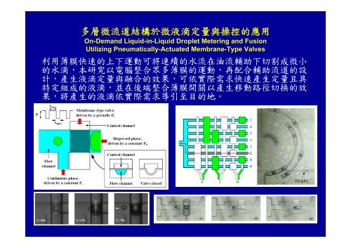
多層微流道結構於微液滴定量與操控的應用<br />
On-Demand Liquid-in-Liquid Droplet Metering and Fusion<br />
Utilizing Pneumatically-Actuated Membrane-Type Valves<br />
利用薄膜快速的上下運動可將連續的水流在油流輔助下切割成微小<br />
的水滴,本研究以電腦整合眾多薄膜的運動,再配合輔助流道的設<br />
計,產生液滴定量與融合的效果,可依實際需求快速產生定量且具<br />
特定組成的液滴,並在後端整合薄膜開關以產生移動路徑切換的效<br />
果,將產生的液滴依實際需求導引至目的地。
IOP PUBLISHING JOURNAL OF MICROMECHANICS AND MICROENGINEERING<br />
J. Micromech. Microeng. 18 (2008) 115005 (10pp) doi:10.1088/0960-1317/18/11/115005<br />
On-demand liquid-in-liquid droplet<br />
metering and fusion utilizing<br />
pneumatically actuated membrane valves<br />
Bo-Chih Lin and Yu-Chuan Su<br />
Department of Engineering and System Science, National Tsing Hua University, Hsinchu, Taiwan<br />
E-mail: ycsu@ess.nthu.edu.tw<br />
Received 5 March 2008, in final form 28 August 2008<br />
Published 23 September 2008<br />
Online at stacks.iop.org/JMM/18/115005<br />
Abstract<br />
This paper presents an active emulsification scheme that is capable of producing<br />
micro-droplets with desired volumes and compositions on demand. Devices with<br />
pneumatically actuated membranes constructed on top of specially designed microfluidic<br />
channels are utilized to meter and fuse liquid-in-liquid droplets. By steadily pressurizing a<br />
fluid and intermittently blocking its flow, droplets with desired volumes are dispersed into<br />
another fluid. Furthermore, droplets from multiple sources are fused together to produce<br />
combined droplets with desired compositions. In the prototype demonstration, a three-layer<br />
PDMS molding and irreversible bonding process was employed to fabricate the proposed<br />
microfluidic devices. For a dispersed-phase flow that is normally blocked by a membrane<br />
valve, the relationship between the volume (V) of a metered droplet and the corresponding<br />
valve open time (T) is found to be approximately V = kTa , in which k and a are constants<br />
determined mainly by the fluid-driving pressures. In addition to the metering device,<br />
functional droplet entrapment, fusion and flow-switching devices were also integrated in the<br />
system to produce desired combined droplets and deliver them to intended destinations upon<br />
request. As such, the demonstrated microfluidic system could potentially realize the<br />
controllability on droplet volume, composition and motion, which is desired for a variety of<br />
chemical and biological applications.<br />
(Some figures in this article are in colour only in the electronic version)<br />
Introduction<br />
Mixing immiscible fluids together results in an emulsion,<br />
which might be defined as a heterogeneous system consisting<br />
of at least one fluid (in the form of tiny droplets) dispersed<br />
within another fluid [1]. An emulsion does not form<br />
spontaneously. It is produced by an emulsification process,<br />
through which interfaces between fluids are created and<br />
stabilized by some emulsifying agents. For example,<br />
massive production of emulsions is traditionally performed<br />
by mechanical agitation, ultrasonication or high-pressure<br />
homogenization [2–4]. However, the results of these<br />
emulsification processes are usually poorly controlled and<br />
highly polydisperse. Monodisperse emulsions are highly<br />
desirable for a variety of applications, including agriculture,<br />
the petroleum industry and pharmaceutical products [5, 6].<br />
Recently, various microfluidic emulsification schemes such<br />
as T-junctions [7–9] and flow-focusing devices [10–12] have<br />
been demonstrated to be capable of producing emulsions in<br />
a consistent and controlled manner. In general, emulsions of<br />
micro-droplets with a
J. Micromech. Microeng. 18 (2008) 115005 B-C Lin and Y-C Su<br />
low sample consumption and high reaction throughput are<br />
expected to significantly accelerate the progress in drug<br />
discovery, protein crystallization and various chemical and<br />
biological screening and synthesis [16–19]. Metering is<br />
the starting point and often the most critical function of a<br />
droplet-based system. In most microfluidic emulsification<br />
schemes, droplet metering is controlled by adjusting the flow<br />
rates of the dispersed and continuous phase fluids, which are<br />
driven by separate syringe pumps. In general, these passive<br />
schemes are capable of producing continuous droplet streams,<br />
but insufficient for adjusting the droplet size and breakup<br />
frequency in a real-time manner [20, 21]. The resulting droplet<br />
volume and breakup frequency are often coupled, and there is<br />
always a transition period following the adjustment of fluid<br />
flow rates. Fusion, in which droplets from multiple sources<br />
are merged together to form a desired combined droplet, is<br />
another crucial function for droplet-based systems. Previously,<br />
droplet fusion has been demonstrated by utilizing size and<br />
frequency matching [22], converging fluidic channels [23], or<br />
patterned ITO electrodes [24], which result in the deceleration<br />
and collision of droplets. However, the coordination of droplet<br />
motion is increasingly difficult, when more droplets are to be<br />
merged. Meanwhile, the employment of syringe pumps as<br />
driving sources has made it costly when trying to scale up the<br />
complexity and productivity of the systems.<br />
To address the need for a better controllability on droplet<br />
size, composition and motion, this paper presents an active<br />
emulsification scheme that employs pneumatic actuation for<br />
the metering, fusion and manipulation of droplets. Devices<br />
with membranes constructed on top of specially designed<br />
micro-fluidic channels are utilized to realize the desired<br />
controllability. Three accomplishments have been achieved<br />
(1) a membrane-actuated metering device that can produce<br />
monodisperse droplets and adjust the droplet size and breakup<br />
frequency in a real-time manner; (2) a droplet entrapment and<br />
fusion device that can selectively and temporally block the<br />
movement of droplets, and facilitate the fusion of the entrapped<br />
droplets; and (3) an active droplet-based microfluidic system<br />
Figure 1. Schematic illustration of the proposed metering scheme.<br />
2<br />
that can produce droplets with desired sizes and compositions<br />
on demand, and deliver the droplets to intended destinations<br />
upon request. As such, the demonstrated microfluidic devices<br />
could potentially realize the controllability on droplet size,<br />
composition and motion, which is desired for various chemical<br />
and biological applications.<br />
Operating principle<br />
A schematic illustration of the proposed metering scheme<br />
is shown in figure 1. A microfluidic device, made up of<br />
a T-junction with a membrane valve mounted on its top, is<br />
employed to control the emulsification process. The structure<br />
of the pneumatically driven, membrane valve is similar to<br />
a previous work [25], while a flat membrane sandwiched<br />
between the control and flow channels is utilized in our design.<br />
Whenever a sufficient pressure is applied to the upper control<br />
channel, the membrane deflects downward and blocks the<br />
lower flow channel. The dispersed and continuous phase<br />
fluids are driven independently by pressures with constant<br />
magnitudes of Pd and Pc, respectively, and fed into the<br />
corresponding microfluidic channels. Without membrane<br />
actuation, liquid-in-liquid droplets with certain dimensions<br />
can be produced at specific frequencies, and the result can be<br />
adjusted by varying the fluid-driving pressures Pd and Pc [7].<br />
The membrane valve is located across the flow channel and<br />
right upstream of the T-junction. It is driven by a constant<br />
pressure P, which is sufficient to deflect the membrane and<br />
completely block the underneath flow channel, and switched<br />
on and off using an electromagnetic actuator. Periodically, the<br />
membrane valve is pneumatically enabled (or pressurized) for<br />
tclose and then disabled for topen. Figure 2 illustrates a complete<br />
metering cycle, in which the valve is opened for 0.075 s.<br />
The color of the membrane turns dark when the membrane<br />
deflects downward. Otherwise, the membrane is transparent<br />
and the flow in the underneath channel could be clearly<br />
observed. Normally, the valve blocks the dispersed-phase<br />
flow completely, while a limited volume of the dispersed-phase
J. Micromech. Microeng. 18 (2008) 115005 B-C Lin and Y-C Su<br />
(a) (d) (g)<br />
(b) (e) (h)<br />
(c) (f ) (i)<br />
fluid can flow through the path when the valve is opened. The<br />
collapse of the membrane breaks the dispersed-phase flow<br />
and produces a discrete droplet, which is then driven away<br />
from the T-junction by the continuous-phase flow. With the<br />
utilization of the membrane valve, the resulting droplet volume<br />
and breakup frequency could be adjusted independently by<br />
varying the open time (topen) and cycle time (tclose + topen) of<br />
the valve, respectively. Totally four control parameters (tclose,<br />
topen, Pd and Pc) are utilized to regulate the metering process,<br />
so liquid-in-liquid droplets could be produced in a flexible and<br />
real-time manner. In general, the resulting breakup frequency<br />
could be either higher or lower than the original one (without<br />
valve actuation), while the resulting droplet volume would<br />
usually be smaller than what is originally achieved. The<br />
proposed metering scheme is applicable to the generation of<br />
both water-in-oil and oil-in-water droplets, when hydrophobic<br />
and hydrophilic flow channels are employed, respectively.<br />
Once droplets (each with specific ingredient and volume)<br />
are produced, they are further fused and mixed together to<br />
produce combined droplets with desired compositions and<br />
volumes. A schematic illustration of the proposed fusion<br />
scheme is shown in figure 3. A microfluidic channel, with<br />
one end temporally blocked by a membrane valve and narrow<br />
lateral branches bypassing the incoming flow, is utilized to<br />
selectively entrap the dispersed droplets. To investigate the<br />
relevant flow behavior and facilitate the implementation of<br />
Figure 2. A complete metering cycle with topen = 0.075 s.<br />
3<br />
Figure 3. Schematic illustration of the proposed fusion scheme.<br />
the proposed fusion scheme, simulation using CFD-ACE+<br />
(CFD Research Corporation) is performed. Figure 4 shows<br />
the simulated stream lines and velocity distribution based on<br />
a simplified channel geometry. For droplets with diameters<br />
larger than half of the width of the central channel, it is<br />
expected that the droplets would be driven into the space<br />
between the valve and the last pair of the bypassing branches,<br />
while the continuous-phase fluid bypasses the blockage and<br />
keeps flowing downstream. With balanced lateral pressure,
J. Micromech. Microeng. 18 (2008) 115005 B-C Lin and Y-C Su<br />
(a) Steam-line distribution<br />
the droplets would remain in the central portion of the main<br />
channel, slow down when moving close to the blockage, and<br />
eventually be entrapped inside the ‘waiting zone’, which is<br />
actually a dead volume when the channel is blocked. In the<br />
proposed fusion scheme, all the droplets to be fused would<br />
be deposited serially into the waiting zone, whose volume<br />
should be set or adjusted accordingly. With droplets restrained<br />
in the waiting zone, an incoming droplet would collide with<br />
the previously deposited ones when it arrives. Driven by the<br />
continuous-phase flow, the newly arrived droplet would push<br />
the previously deposited ones moving further into the dead<br />
end of the waiting zone, and stop when it is completely<br />
into the waiting zone. Eventually, the entrapped droplets<br />
would fuse together after a certain period of time. As such,<br />
combined droplets with desired volumes and compositions<br />
could be produced by coordinating the proposed metering and<br />
fusion schemes. Afterward, the membrane valve is opened<br />
and the combined droplet is driven downstream for further<br />
processing.<br />
Fabrication processes<br />
A three-layer PDMS molding and irreversible bonding process<br />
were employed to fabricate the proposed microfluidic devices,<br />
as illustrated in figure 5. First of all, a layer of 25 μm thick<br />
positive photoresist (9260, AZ Electronic Materials) was spin<br />
(b) Velocity distribution<br />
Figure 4. Simulation results of the proposed fusion scheme.<br />
4<br />
coated and patterned on top of a clean silicon wafer to fabricate<br />
the mold used for the duplication of the flow-channel layer.<br />
Afterward, the patterned photoresist layer was baked at 120 ◦ C<br />
for 30 min, during which the photoresist reflowed and its<br />
profile became rounded. Meanwhile, the mold used for the<br />
duplication of control-channel layer was fabricated by coating<br />
and patterning a 10 μm thick layer of negative photoresist<br />
(SU-8, MicroChem) on top of a clean silicon wafer. After<br />
the two photoresist molds were fully cured, they were placed<br />
in a desiccator under vacuum for 3 h with a vial containing<br />
a few drops of 1H, 1H, 2H, 2H-perfluorooctyl-trichlorosilane<br />
(Fluka) to silanize the surfaces [26]. The purpose of this<br />
silanization step is to facilitate the removal of polymeric<br />
replicas (from the molds) after the following casting process.<br />
A mixture of 10:1 PDMS pre-polymer and curing agent<br />
(Sylgard 184, Dow-Corning) was stirred thoroughly and then<br />
degassed under vacuum to remove entrapped air bubbles. The<br />
casting and bonding process started with the deposition of a<br />
thin valve membrane on top of a clean silicon wafer. About<br />
one tenths of the PDMS mixture was spin coated on the wafer<br />
at 1500 rpm for 30 s, which yielded a thickness of roughly<br />
30 μm, and cured for 15 min at 85 ◦ C. Meanwhile, about<br />
half of the PDMS mixture was poured onto the flow-channel<br />
mold, degassed, cured for 15 min at 85 ◦ C, and then peeled<br />
off from the mold. Afterward, the flow-channel layer was<br />
pressed and bonded on top of the 30 μm thick membrane, and
J. Micromech. Microeng. 18 (2008) 115005 B-C Lin and Y-C Su<br />
(a)<br />
(b)<br />
(c)<br />
Figure 5. A three-layer PDMS molding and irreversible bonding process.<br />
left undisturbed for at least 1 h at 85 ◦ C for the bonding to<br />
take effect. The bonded two-layer PDMS structure was then<br />
peeled off from the silicon wafer, and punched through with a<br />
sharp metal-tube array to fabricate the holes for multiple inlets<br />
and outlets. Afterward, it was cleaned in an ultrasonic bath to<br />
remove residual debris from its surface. Meanwhile, the left<br />
PDMS mixture was poured onto the control-channel mold,<br />
degassed, cured for 1 h at 85 ◦ C, and then peeled off from<br />
the mold. The surfaces of the two-layer PDMS structure (on<br />
the membrane side) and the duplicated control-channel layer<br />
were then treated with a hand-held corona treater (BD-20AC,<br />
Electro-Technic Products), which ionizes the surrounding<br />
air and creates localized plasma to activate the surfaces for<br />
irreversible bonding. The intensity of the corona was set at a<br />
relatively low level in order to produce a stable but soft corona<br />
with minimal crackling and sparking [27]. The wire electrode<br />
was positioned approximately 3 mm above the treated surface,<br />
and scanned back and forth for 30 s to 1 min, depending on<br />
the size of the surface. The corona-treated surfaces were then<br />
pressed together and left undisturbed for at least 1 h at 85 ◦ Cfor<br />
the bonding to take effect. At the end, multiple PTFE tubes<br />
were inserted into the punched holes to build the necessary<br />
interconnection for sample injection and discharge.<br />
Experimental details<br />
In the prototype demonstration, water-in-oil droplets were<br />
produced using de-ionized water and oleic acid (Aldrich)<br />
with 5 wt% Span 80 (Aldrich) as dispersed and continuous<br />
phase fluids, respectively. In addition to oleic acid (viscosity<br />
28 mPa s), hexadecane (viscosity 8 mPa s) and silicone oil<br />
(viscosity 50 mPa s) were also tested to investigate the effects<br />
caused by the viscosity of continuous-phase fluid. The detailed<br />
experimental setup is illustrated in figure 6. An air compressor<br />
5<br />
(Model 3-4, Jun-Air) with its output set at 500 kPa was<br />
employed as the single source to drive the operation. Each fluid<br />
sample was stored in a separate plastic container, which was<br />
fed with pressurized air from the top to drive the fluid flowing<br />
through the bottom tube and into the downstream microfluidic<br />
devices. The actual driving pressure applied on each container<br />
was adjusted independently by a separate pressure regulator<br />
(IR1000-01G, SMC). Meanwhile, the actuation of each<br />
membrane valve was controlled independently by a separate<br />
electromagnetic valve (VK332-5G-M5, SMC), whose action<br />
was governed by a computer-controlled relay circuitry. A<br />
governing program developed and executed under a software<br />
environment (LabVIEW, National Instruments), cooperating<br />
with a set of hardware adapter and connector (PCI-6220 +<br />
CB-68LP), was employed to coordinate the actuation of the<br />
prototype system. As such, the operation can be either preprogrammed<br />
or responding to demand in a real-time manner.<br />
The formation of liquid-in-liquid droplets was observed under<br />
an optical microscope and the images were recorded using a<br />
CCD camera also controlled by the computer. The resulting<br />
droplets were driven into a 400 μm deep reservoir, where<br />
the droplets would be perfect spheres without unwanted<br />
deformation. The volumes of the resulting droplets were then<br />
estimated based on the observed spherical diameters. For the<br />
demonstration of 1 × 8 flow switching, three electromagnetic<br />
switches (VK3120-5G-M5, SMC) were utilized to control six<br />
sets of membrane valves.<br />
Results and discussion<br />
Prior to the metering and fusion trials, the performance of<br />
the membrane valve was characterized with the flow channel<br />
empty and open to the atmosphere. With a deformable area of<br />
150 μm (the width of the flow channel) ×150 μm (the width
J. Micromech. Microeng. 18 (2008) 115005 B-C Lin and Y-C Su<br />
Figure 6. Experimental setup of the proposed droplet metering and fusion schemes.<br />
Table 1. Measured droplet sizes and variations at various valve open time when Pd = 2.3 kPa and Pc = 3.9 kPa.<br />
Valve open time (s) 0.05 0.1 0.2 0.4 0.8 1.6 2.8<br />
Average droplet diameter (μm) 10.19 17.57 27.16 38.70 51.92 68.36 95.70<br />
Standard variation (%) 3.27 3.72 4.74 1.22 1.49 3.29 1.35<br />
Average droplet volume (pl) 0.55 2.84 10.50 30.34 73.27 167.2 458.8<br />
of the control channel) and a membrane thickness of roughly<br />
30 μm, the minimum pressure required to deflect the<br />
membrane and completely block the 25 μm high flow channel<br />
was measured to be 75 kPa. At this actuation pressure, the<br />
response time of the membrane structure was found to be<br />
roughly 0.02 s, which could be further reduced if a higher<br />
actuation pressure is employed. The minimum valve open<br />
(or close) time actually tested in our experiments was 0.05 s,<br />
since the utilized electromagnetic valves were not able to<br />
operate correspondingly at frequencies higher than 15 Hz.<br />
In the case when the open (or close) time is shorter than the<br />
response time of the valve, the valve would only be partially<br />
opened (or closed). When working fluids are pressurized<br />
and fed into the flow channel, the actual minimum pressure<br />
for complete blockage and the resulting response time of<br />
the membrane structure would vary accordingly. Usually,<br />
fluids with higher viscosities would require higher pressure<br />
and longer time for operation.<br />
In the metering trials, the resulting droplet volume (V)<br />
was mainly controlled by the valve open time (T = topen)<br />
and the driving pressures of the dispersed and continuous<br />
phase fluids (Pd and Pc). For steady flow, the volume is<br />
expected to be approximately equal to the product of the<br />
resulting dispersed-phase flow rate and the valve open time.<br />
However, the flow is actually transient right after the valve is<br />
opened. The production of a small droplet (with an estimated<br />
volume of 11 pL) is illustrated in figure 2. The retreat of the<br />
membrane causes a negative pressure gradient, which sucks<br />
6<br />
in the fluids and in turn shapes the front end of the dispersedphase<br />
flow into a cone (as shown in figure 2(c)). Meanwhile,<br />
the bulk dispersed-phase fluid is accelerated and starts to flow.<br />
After opened for a short period of time, the membrane valve<br />
is closed and the dispersed-phase flow is broken, while the<br />
volume left to the center line of the membrane is shaped into<br />
a droplet. In general, the volume of the resulting droplet<br />
would not be linearly proportional to the valve open time,<br />
because of the transient effects caused by the retreat of the<br />
membrane and the acceleration of the disperse-phase fluid<br />
from being blocked. The measured relationship between the<br />
resulting droplet volume and the valve open time (with DI<br />
water and oleic acid as dispersed and continuous phase fluids,<br />
respectively) is illustrated in figure 7. For condition 1 (Pd =<br />
2.3 kPa and Pc = 3.9 kPa), the droplet volume fell from 458.8<br />
to 0.55 pL, while the valve open time decreased from 2.8<br />
to 0.05 s. It is found that a 56 times decrease in the valve<br />
open time had resulted in a more than 800 times fall in the<br />
droplet volume. This nonlinearity is believed to result from<br />
the transient effects just mentioned, which are more significant<br />
when the valve open time is shorter. Meanwhile, table 1<br />
shows the droplet sizes and variations at various valve open<br />
time measured under condition 1. It is noted that the diameter<br />
deviation of the resulting droplets is usually less than 5% of<br />
the average value, which indicates a desired monodisperse<br />
character. When the fluid-driving pressures (Pd and Pc) vary,<br />
the relationship between the resulting droplet volume and the<br />
valve open time would change as well. Comparatively, when
J. Micromech. Microeng. 18 (2008) 115005 B-C Lin and Y-C Su<br />
Volume (pL)<br />
1000<br />
100<br />
10<br />
1<br />
V = 1093.9T 1.0085<br />
R 2 = 0.9975<br />
V = 99.303T 1.5928<br />
V = 20.621T 2.0775<br />
R 2 = 0.9738<br />
R 2 = 0.9871<br />
0.1<br />
0.01 0.1 1 10<br />
Time (second)<br />
Figure 7. Measured relationship between resulting droplet volume (V) and valve open time (T).<br />
Figure 8. Captured water–oil interfaces with (Pd/Pc)3 > (Pd/Pc)2 > (Pd/Pc)1.<br />
Figure 9. Production of a droplet stream with a preset size order of 1×,2×,3×, 4×,3×,2×, 1×.<br />
Pc was raised from 3.9 to 4.5 kPa (condition 2 in figure 7),<br />
the resulting droplet volume became smaller at the same<br />
valve open time and plummeted even faster while the valve<br />
open time decreased. It is expected that the reduction in the<br />
Pd/Pc ratio would lower the resulting dispersed-phase flow<br />
rate and amplify the transient effects. Meanwhile, when Pd<br />
was raised from 2.3 to 4.5 kPa (condition 3 in figure 7), the<br />
relationship between the resulting droplet volume and the valve<br />
open time became closer to linear, most likely due to the<br />
decline in the transient effects. In general, the relationship<br />
between the resulting droplet volume and the valve open time<br />
is found to be approximately V = kT a , where k and a are<br />
constants determined mainly by the fluid-driving pressures<br />
when a specific fluid combination is utilized. For condition 1,<br />
constant a is estimated to be 1.59 and k is about 99.30, while<br />
(a, k) are (2.08, 20.62) and (1.01, 1094) for conditions 2 and 3,<br />
7<br />
respectively. Meanwhile the employment of a continuousphase<br />
fluid with higher viscosity would usually enhance the<br />
transient effects and therefore result in higher nonlinearity and<br />
the reduction in dispersed droplet volume. In addition, it is<br />
also found that the cone angles of the water–oil interfaces<br />
decreased when the corresponding Pd/Pc ratios increased, as<br />
shown in figure 8. Based on the measured results, droplets with<br />
desired sizes could be produced with negligible delay by the<br />
proposed metering scheme. To demonstrate the functionality<br />
of this scheme, a LabVIEW program that allows users to assign<br />
the individual size and order of the output droplet stream<br />
was developed. By adjusting merely the valve open time<br />
correspondingly, the production of a droplet stream with a<br />
preset size order of 1×,2×,3×,4×,3×,2×,1× was realized<br />
as shown in figure 9.
J. Micromech. Microeng. 18 (2008) 115005 B-C Lin and Y-C Su<br />
(1)<br />
(2)<br />
(3)<br />
(1) t0<br />
(2) t0+0.03s<br />
Valve closed<br />
Valve opened<br />
(4)<br />
(5)<br />
(6)<br />
(4) t0+0.17s (7) t0+0.37s<br />
(5) t0+0.23s<br />
(8) t0+0.43s<br />
(3) t0+0.1s (6) t0+0.3s (9) t0+0.5s<br />
(a)<br />
(b)<br />
Figure 10. (a) Recorded fusion sequences of (a) four serially entrapped droplets and (b) two entrapped droplets accelerated by the retreat of<br />
the membrane.<br />
Figure 10(a) shows a recorded fusion sequence, in which<br />
the diameters of the incoming droplets were about half of<br />
the width of the middle main channel. Although all the<br />
three downstream flow channels are intersected by a control<br />
channel (valve), only the flow in the main channel would be<br />
completely blocked when the valve is activated. The droplet<br />
8<br />
(7)<br />
(8)<br />
(9)<br />
arrived first was entrapped in front of the valve, while the<br />
continuous-phase flow bypassed the valve. The following<br />
droplets were also driven into the waiting zone, collided and<br />
eventually merged with the previously entrapped droplets. If<br />
the waiting zone is fully occupied, the incoming droplets would<br />
be driven through the bypassing branches and discharged.
J. Micromech. Microeng. 18 (2008) 115005 B-C Lin and Y-C Su<br />
(a) (b)<br />
Figure 11. Schematic illustration (a) and photograph (b)ofa1× 8 flow switch.<br />
The fusion did not happen right after the droplets collided<br />
with each other. Instead, the draining of the film between<br />
two consecutive droplets would last for a certain period of<br />
time, before the two droplets could finally merge together<br />
[28]. To shorten the process time, the entrapped droplets<br />
were discharged into a diverging channel, in which fusion was<br />
accelerated by a decelerating velocity gradient, soon after the<br />
collision. Meanwhile, the fusion of the entrapped droplets can<br />
also be accelerated by the retreat of the membrane. The retreat<br />
causes a negative pressure gradient, which sucks in the fluids<br />
and in turn accelerates the draining of the liquid film between<br />
the entrapped droplets, as shown in figure 10(b). It is observed<br />
that the droplets fused together right after (in 0.03 s) the valve<br />
was opened and mixed rapidly after the fusion. Compared to<br />
other fusion schemes, our approach can handle more droplets<br />
and tolerate higher variations in droplet size and the spacing<br />
between consecutive droplets. Once all the metering, fusion<br />
and mixing steps had been completed, the resulting droplets<br />
were selectively delivered into corresponding downstream<br />
paths as requested. Figure 11 illustrates a 1 × 8 flow<br />
switch [29] that was employed to control the delivery of<br />
droplets. Six (=2 × 3) control channels actuated by three<br />
external switching valves could result in 8 (=2 3 ) different<br />
delivery paths. For example, an actuation status of 0–1–0, as<br />
illustrated in figure 11(a), would direct the flow into the No. 2<br />
channel. This concept was implemented and integrated with<br />
the metering and fusion devices, as shown in figure 11(b). As<br />
such, the proposed schemes and the integrated system would<br />
be able to produce micro-droplets with desired volumes and<br />
compositions, and deliver the resulting droplets into one of the<br />
eight destinations upon request.<br />
Conclusion<br />
We have successfully demonstrated an active emulsification<br />
scheme that can produce micro-droplets with desired volumes<br />
and compositions on demand. Devices with pneumatically<br />
actuated membrane valves constructed on top of specially<br />
9<br />
designed microfluidic channels are employed to meter and<br />
fuse liquid-in-liquid droplets. By steadily pressurizing a fluid<br />
and intermittently blocking its flow, droplets with desired<br />
volumes are dispersed into another fluid. Furthermore,<br />
droplets from multiple sources are fused together to produce<br />
combined droplets with desired compositions. In the prototype<br />
demonstration, a three-layer PDMS molding and irreversible<br />
bonding process was utilized to fabricate the proposed<br />
microfluidic devices. The volume (V) of the dispersed droplets<br />
is found to be mainly controlled by the valve open time (T),<br />
and the relationship could be approximated as V = kT a ,in<br />
which k and a are pressure-dependent constants. For a water<br />
flow that was driven by a constant-pressure source (at 2.3 kPa)<br />
and normally blocked by a membrane valve, the volume of the<br />
resulting droplets fell from 458.8 to 0.55 pL (a >800 times<br />
drop), while the valve open time decreased from 2.8 to 0.05 s<br />
(a merely 56 times reduction). The nonlinearity is believed to<br />
result from transient effects, which are more significant when<br />
the valve open time is shorter. Meanwhile it is also noted<br />
that under the same conditions, the diameter deviation of the<br />
resulting droplets was usually less than 5% of the average<br />
value, which indicates a desired monodisperse character. In<br />
order to produce desired combined droplets and deliver them<br />
to intended destinations, functional droplet entrapment, fusion<br />
and flow switching devices, which also utilize the membrane<br />
valves, were integrated with the metering devices. With four<br />
valve control lines, multiple droplets can be entrapped, fused<br />
and delivered to one of the eight destinations. As such, the<br />
demonstrated microfluidic system could potentially realize the<br />
controllability on droplet volume, composition and motion,<br />
which is desired for a variety of biological and chemical<br />
applications.<br />
Acknowledgments<br />
This work was supported in part by the National Science<br />
Council of Taiwan under Contract No. NSC 96-2221-E-007-<br />
116-MY3. The demonstrated systems were fabricated in the
J. Micromech. Microeng. 18 (2008) 115005 B-C Lin and Y-C Su<br />
ESS Micro-fabrication Lab at National Tsing Hua University,<br />
Taiwan.<br />
References<br />
[1] Becher P 1965 Emulsions: Theory and Practice (New York:<br />
Reinhold)<br />
[2] Lissant K J 1974 Emulsions and Emulsion Technology (New<br />
York: Dekker)<br />
[3] de Castro M D L and Priego-Capote F 2007<br />
Ultrasound-assisted preparation of liquid samples Talanta<br />
72 321–34<br />
[4] Schultz S, Wagner G, Urban K and Ulrich J 2004<br />
High-pressure homogenization as a process for emulsion<br />
formation Chem. Eng. Technol. 27 361–8<br />
[5] Schramm L L 2005 Emulsions, Foams, and Suspensions:<br />
Fundamentals and Applications (Weinheim: Wiley-VCH)<br />
[6] Benita S 1996 Microencapsulation: Methods and Industrial<br />
Application (New York: Dekker)<br />
[7] Thorsen T, Roberts R W, Arnold F H and Quake S R<br />
2001 Dynamic pattern formation in a vesicle-generating<br />
microfluidic device Phys. Rev. Lett. 86 4163–6<br />
[8] Nisisako T, Torii T and Higuchi T 2002 Droplet formation in a<br />
microchannel network Lab Chip 2 24–6<br />
[9] Dendukuri D, Tsoi K, Hatton T A and Doyle P S 2005<br />
Controlled synthesis of nonspherical microparticles using<br />
microfluidics Langmuir 21 2113–6<br />
[10] Anna S L, Bontoux N and Stone H A 2003 Formation of<br />
dispersions using “flow focusing” in microchannels<br />
Appl. Phys. Lett. 82 364–6<br />
[11] Garstecki P, Gitlin I, DiLuzio W and Whiteside G M<br />
2004 Formation of monodisperse bubbles in a<br />
microfluidic flow-focusing device Appl. Phys. Lett.<br />
85 2649–51<br />
[12] Tan Y C, Fisher J S, Lee A I, Cristini V and Lee A P 2004<br />
Design of microfluidic channel geometries for the control of<br />
droplet volume, chemical concentration, and sorting<br />
Lab Chip 4 292–8<br />
[13] Song H, Chen D L and Ismagilov R F 2006 Reactions in<br />
droplets in microfluidic channels Angew. Chem. Int. Edit.<br />
45 7336–56<br />
[14] Kelly B T, Baret J C, Taly V and Griffiths D 2007<br />
Miniaturizing chemistry and biology in microdroplets<br />
Chem. Commun. 18 1773–88<br />
10<br />
[15] Leamon J H, Link D R, Egholm M and Rothberg J M 2006<br />
Overview: methods and applications for droplet<br />
compartmentalization of biology Nat. Methods 3 541–3<br />
[16] Zheng B, Roach L S and Ismagilov R F 2003 Screening of<br />
protein crystallization conditions on a microfluidic chip<br />
using nanoliter-size droplets J. Am. Chem. Soc.<br />
125 11170–1<br />
[17] Martin K, Henkel T, Baier V, Grodrian A, Schon T, Roth M,<br />
Kohler J M and Metze J 2003 Generation of larger numbers<br />
of separated microbial populations by cultivation in<br />
segmented-flow microdevices Lab Chip 3 202–7<br />
[18] Khan S A, Gunther A, Schmidt M A and Jensen K F 2004<br />
Microfluidic synthesis of colloidal silica Langmuir<br />
20 8604–11<br />
[19] Dittrich P S and Manz A 2006 Lab-on-a-chip: microfluidics in<br />
drug discovery Nat. Rev. Drug Discovery 5 210–8<br />
[20] Joanicot M and Ajdari A 2005 Droplet control for<br />
microfluidics Science 309 887–8<br />
[21] Christopher G F and Anna S L 2007 Microfluidic methods for<br />
generating continuous droplet streams J. Phys. D Appl.<br />
Phys. 40 R319–36<br />
[22] Song H, Tice J D and Ismagilov R F 2003 A microfluidic<br />
system for controlling reaction networks in time Angew.<br />
Chem. Int. Edit. 42 768–72<br />
[23] Hung L H, Choi K M, Tseng W Y, Tan Y C, Shea K J and<br />
Lee A P 2006 Alternating droplet generation and controlled<br />
dynamic droplet fusion in microfluidic device for CdS<br />
nanoparticle synthesis Lab Chip 6 174–8<br />
[24] Link D R, Grasland-Mongrain E, Duri A, Sarrazin F, Cheng Z,<br />
Cristobal G, Marquez M and Weitz D A 2006 Electric<br />
control of droplets in microfluidic devices Angew. Chem.<br />
Int. Edit. 45 2556–60<br />
[25] Unger M A, Chou H P, Thorsen T, Scherer A and Quake S R<br />
2000 Monolithic microfabricated valves and pumps by<br />
multilayer soft lithography Science 288 113–6<br />
[26] Duffy D C, McDonald J C, Schueller O J A and<br />
Whitesides G M 1998 Rapid prototyping of microfluidic<br />
systems in poly(dimethylsiloxane) Anal. Chem. 70 4974–84<br />
[27] Haubert K, Drier T and Beebe D 2006 PDMS bonding by<br />
means of a portable, low-cost corona system Lab Chip<br />
6 1548–9<br />
[28] Chesters A K 1991 The modelling of coalescence processes in<br />
fluid-liquid dispersions: a review of current understanding<br />
Trans. Inst. Chem. Eng. A 69 259–70<br />
[29] Thorsen T, Maerkl S J and Quake S R 2002 Microfluidic<br />
large-scale integration Science 298 580–4