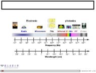
Acceleration, Shock and Vibration Sensors
Acceleration, Shock and Vibration Sensors
Acceleration, Shock and Vibration Sensors

Create successful ePaper yourself
Turn your PDF publications into a flip-book with our unique Google optimized e-Paper software.
137<br />
C H A P T E R 5<br />
<strong>Acceleration</strong>, <strong>Shock</strong> <strong>and</strong> <strong>Vibration</strong> <strong>Sensors</strong><br />
Craig Aszkler, <strong>Vibration</strong> Products Division Manager, PCB Piezotronics, Inc.<br />
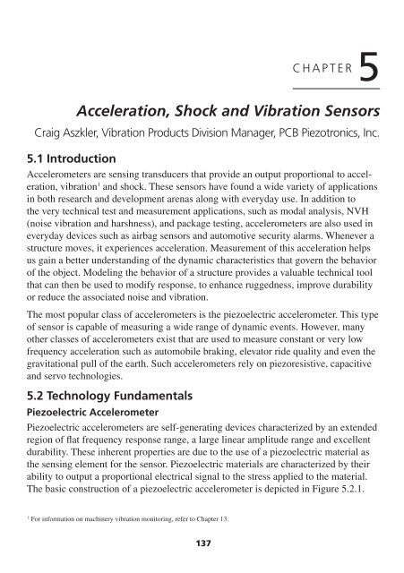
5.1 Introduction<br />
Accelerometers are sensing transducers that provide an output proportional to acceleration,<br />
vibration 1 <strong>and</strong> shock. These sensors have found a wide variety of applications<br />
in both research <strong>and</strong> development arenas along with everyday use. In addition to<br />
the very technical test <strong>and</strong> measurement applications, such as modal analysis, NVH<br />
(noise vibration <strong>and</strong> harshness), <strong>and</strong> package testing, accelerometers are also used in<br />
everyday devices such as airbag sensors <strong>and</strong> automotive security alarms. Whenever a<br />
structure moves, it experiences acceleration. Measurement of this acceleration helps<br />
us gain a better underst<strong>and</strong>ing of the dynamic characteristics that govern the behavior<br />
of the object. Modeling the behavior of a structure provides a valuable technical tool<br />
that can then be used to modify response, to enhance ruggedness, improve durability<br />
or reduce the associated noise <strong>and</strong> vibration.<br />
The most popular class of accelerometers is the piezoelectric accelerometer. This type<br />
of sensor is capable of measuring a wide range of dynamic events. However, many<br />
other classes of accelerometers exist that are used to measure constant or very low<br />
frequency acceleration such as automobile braking, elevator ride quality <strong>and</strong> even the<br />
gravitational pull of the earth. Such accelerometers rely on piezoresistive, capacitive<br />
<strong>and</strong> servo technologies.<br />
5.2 Technology Fundamentals<br />
Piezoelectric Accelerometer<br />
Piezoelectric accelerometers are self-generating devices characterized by an extended<br />
region of flat frequency response range, a large linear amplitude range <strong>and</strong> excellent<br />
durability. These inherent properties are due to the use of a piezoelectric material as<br />
the sensing element for the sensor. Piezoelectric materials are characterized by their<br />
ability to output a proportional electrical signal to the stress applied to the material.<br />
The basic construction of a piezoelectric accelerometer is depicted in Figure 5.2.1.<br />
1 For information on machinery vibration monitoring, refer to Chapter 13.
Chapter 5<br />
Piezoelectric Element<br />
Preload Ring<br />
Seismic Mass<br />
Accelerometer Base<br />
Figure 5.2.1: Basic piezoelectric accelerometer construction.<br />
The active elements of the accelerometer are the piezoelectric elements. The elements<br />
act as a spring, which has a stiffness k, <strong>and</strong> connect the base of the accelerometer to<br />
the seismic masses. When an input is present at the base of the accelerometer, a force<br />
(F) is created on piezoelectric material proportional to the applied acceleration (a)<br />
<strong>and</strong> size of the seismic mass (m). (The sensor is governed by Newton’s law of motion<br />
F = ma.) The force experienced by the piezoelectric crystal is proportional to the seismic<br />
mass times the input acceleration. The more mass or acceleration, the higher the<br />
applied force <strong>and</strong> the more electrical output from the crystal.<br />
The frequency response of the sensor is determined by the resonant frequency of the<br />
sensor, which can generally be modeled as a simple single degree of freedom system.<br />
Using this system, the resonant frequency (ω) of the sensor can be estimated by:<br />
ω = k / m .<br />
The typical frequency response of piezoelectric accelerometers is depicted in Figure 5.2.2.<br />
Piezoelectric accelerometers can be broken down into two main categories that define<br />
their mode of operation.<br />
Internally amplified accelerometers<br />
or IEPE (internal<br />
Relative<br />
Amplitude<br />
Resonance Peak<br />
electronic piezoelectric) con-<br />
<strong>Vibration</strong> of<br />
tain built-in microelectronic<br />
Seismic Mass<br />
signal conditioning. Charge<br />
mode accelerometers con-<br />
Useful Frequency Range<br />
tain only the self-generating<br />
piezoelectric sensing element<br />
<strong>and</strong> have a high impedance<br />
<strong>Vibration</strong> of Base<br />
charge output signal.<br />
Relative Frequency<br />
Figure 5.2.2 Typical frequency response<br />
of piezoelectric accelerometer.<br />
138
<strong>Acceleration</strong>, <strong>Shock</strong> <strong>and</strong> <strong>Vibration</strong> <strong>Sensors</strong><br />
IEPE Accelerometers<br />
IEPE sensors incorporate built-in, signal-conditioning electronics that function to<br />
convert the high-impedance charge signal generated by the piezoelectric sensing element<br />
into a usable low-impedance voltage signal that can be readily transmitted, over<br />
ordinary two-wire or coaxial cables, to any voltage readout or recording device. The<br />
low-impedance signal can be transmitted over long cable distances <strong>and</strong> used in dirty<br />
field or factory environments with little degradation. In addition to providing crucial<br />
impedance conversion, IEPE sensor circuitry can also include other signal conditioning<br />
features, such as gain, filtering <strong>and</strong> self-test features. The simplicity of use, high<br />
accuracy, broad frequency range, <strong>and</strong> low cost of IEPE accelerometer systems make<br />
them the recommended type for use in most vibration or shock applications. However,<br />
an exception to this assertion must be made for circumstances in which the temperature<br />
at the installation point exceeds the capability of the built-in circuitry. The routine<br />
upper temperature limit of IEPE accelerometers is 250°F (121°C); however, specialty<br />
units are available that operate to 350°F (175°C).<br />
IEPE is a generic industry term for sensors with built-in electronics. Many accelerometer<br />
manufacturers use their own registered trademarks or trade name to signify sensors<br />
with built-in electronics. Examples of these names include: ICP® (PCB Piezotronics),<br />
Deltatron (Bruel & Kjaer), Piezotron (Kistler Instruments), <strong>and</strong> Isotron (Endevco), to<br />
name a few.<br />
The electronics within IEPE accelerometers<br />
require excitation power from a constantcurrent,<br />
DC voltage source. This power<br />
source is sometimes built into vibration<br />
meters, FFT analyzers <strong>and</strong> vibration data<br />
collectors. A separate signal conditioner is<br />
required when none is built into the readout.<br />
In addition to providing the required<br />
excitation, power supplies may also incor- Figure 5.2.3: Typical IEPE system.<br />
porate additional signal conditioning, such<br />
as gain, filtering, buffering <strong>and</strong> overload indication. The typical system set-ups for<br />
IEPE accelerometers are shown in Figure 5.2.3.<br />
139
Chapter 5<br />
Charge Mode Accelerometers<br />
Charge mode sensors output a high-impedance, electrical charge signal that is generated<br />
directly by the piezoelectric sensing element. It should be noted that this signal<br />
is sensitive to corruption from environmental influences <strong>and</strong> cable-generated noise.<br />
Therefore it requires the use of a special low noise cable. To conduct accurate measurements,<br />
it is necessary to condition this signal to a low-impedance voltage before<br />
it can be input to a readout or recording device. A charge amplifier or in-line charge<br />
converter is generally used for this purpose. These devices utilize high-input-impedance,<br />
low-output-impedance charge amplifiers with capacitive feedback. Adjusting<br />
the value of the feedback capacitor alters the transfer function or gain of the charge<br />
amplifier.<br />
Typically, charge mode accelerometers are used when high temperature survivability<br />
is required. If the measurement signal must be transmitted over long distances, it is<br />
recommended to use an in-line charge converter, placed near the accelerometer. This<br />
minimizes the chance of noise. In-line charge converters can be operated from the<br />
same constant-current excitation power source as IEPE accelerometers for a reduced<br />
system cost. In either case, the use of a special low noise cable is required between<br />
the accelerometer <strong>and</strong> the charge converter to minimize vibration induced triboelectric<br />
noise.<br />
Figure 5.2.4: Typical in-line charge converter system.<br />
140<br />
Figure 5.2.5:<br />
Laboratory charge<br />
amplifier system.
<strong>Acceleration</strong>, <strong>Shock</strong> <strong>and</strong> <strong>Vibration</strong> <strong>Sensors</strong><br />
Sophisticated laboratory-style charge amplifiers usually include adjustments for<br />
normalizing the input signal <strong>and</strong> altering the feedback capacitor to provide the desired<br />
system sensitivity <strong>and</strong> full-scale amplitude range. Filtering also may be used to tailor<br />
the high <strong>and</strong> low frequency response. Some charge amplifiers provide dual-mode operation,<br />
which provides power for IEPE accelerometers <strong>and</strong> conditions charge mode<br />
sensors.<br />
Because of the high-impedance nature of the output signal generated by charge mode<br />
accelerometers, several important precautionary measures must be followed. As<br />
noted above, always be attentive to motion induced (triboelectric) noise in the cable<br />
<strong>and</strong> mitigate by using specially treated cable. Also, always maintain high insulation<br />
resistance of the accelerometer, cabling, <strong>and</strong> connectors. To ensure high insulation<br />
resistance, all components must be kept dry <strong>and</strong> clean. This will help minimize potential<br />
problems associated with noise <strong>and</strong>/or signal drift.<br />
Piezoelectric Sensing Materials<br />
Two categories of piezoelectric materials that are predominantly used in the design<br />
of accelerometers are quartz <strong>and</strong> polycrystalline ceramics. Quartz is a natural crystal,<br />
while ceramics are man-made. Each material offers certain benefits. The material<br />
choice depends on the particular performance features desired of the accelerometer.<br />
Quartz is widely known for its ability to perform accurate measurement tasks <strong>and</strong><br />
contributes heavily in everyday applications for time <strong>and</strong> frequency measurements.<br />
Examples include everything from wristwatches <strong>and</strong> radios to computers <strong>and</strong> home<br />
appliances. Accelerometers benefit from several unique properties of quartz. Since<br />
quartz is naturally piezoelectric, it has no tendency to relax to an alternative state <strong>and</strong><br />
is considered the most stable of all piezoelectric materials. This important feature<br />
provides quartz accelerometers with long-term stability <strong>and</strong> repeatability. Also, quartz<br />
does not exhibit the pyroelectric effect (output due to temperature change), which provides<br />
stability in thermally active environments. Because quartz has a low capacitance<br />
value, the voltage sensitivity is relatively high compared to most ceramic materials,<br />
making it ideal for use in voltage-amplified systems. Conversely, the charge sensitivity<br />
of quartz is low, limiting its usefulness in charge-amplified systems, where low<br />
noise is an inherent feature.<br />
A variety of ceramic materials are used for accelerometers, depending on the requirements<br />
of the particular application. All ceramic materials are man-made <strong>and</strong><br />
are forced to become piezoelectric by a polarization process. This process, known as<br />
“poling,” exposes the material to a high-intensity electric field. This process aligns the<br />
electric dipoles, causing the material to become piezoelectric. If ceramic is exposed to<br />
141
Chapter 5<br />
temperatures exceeding its range, or large electric fields, the piezoelectric properties<br />
may be drastically altered. There are several classifications of ceramics. First, there<br />
are high-voltage-sensitivity ceramics that are used for accelerometers with built-in,<br />
voltage-amplified circuits. There are high-charge-sensitivity ceramics that are used for<br />
charge mode sensors with temperature ranges to 400°F (205°C). This same type of<br />
crystal is used in accelerometers that use built-in charge-amplified circuits to achieve<br />
high output signals <strong>and</strong> high resolution. Finally, there are high-temperature piezoceramics<br />
that are used for charge mode accelerometers with temperature ranges over<br />
1000°F (537°C) for monitoring engine manifolds <strong>and</strong> superheated turbines.<br />
Structures for Piezoelectric Accelerometers<br />
A variety of mechanical configurations are available to perform the transduction principles<br />
of a piezoelectric accelerometer. These configurations are defined by the nature<br />
in which the inertial force of an accelerated mass acts upon the piezoelectric material.<br />
There are three primary configurations in use today: shear, flexural beam, <strong>and</strong> compression.<br />
The shear <strong>and</strong> flexural modes are the most common, while the compression<br />
mode is used less frequently, but is included here as an alternative configuration.<br />
Shear Mode<br />
Shear mode accelerometer designs bond,<br />
or “s<strong>and</strong>wich,” the sensing material<br />
between a center post <strong>and</strong> seismic mass.<br />
A compression ring or stud applies a<br />
preload force required to create a rigid<br />
linear structure. Under acceleration, the<br />
mass causes a shear stress to be applied<br />
to the sensing material. This stress<br />
results in a proportional electrical output<br />
by the piezoelectric material. The output<br />
is then collected by the electrodes <strong>and</strong><br />
transmitted by lightweight lead wires<br />
to either the built-in signal conditioning<br />
circuitry of ICP® sensors, or directly Figure 5.2.6: Shear mode accelerometer.<br />
to the electrical connector for a charge<br />
mode type. By isolating the sensing crystals from the base <strong>and</strong> housing, shear accelerometers<br />
excel in rejecting thermal transient <strong>and</strong> base bending effects. Also, the shear<br />
geometry lends itself to small size, which promotes high frequency response while<br />
minimizing mass loading effects on the test structure. With this combination of ideal<br />
characteristics, shear mode accelerometers offer optimum performance.<br />
142
<strong>Acceleration</strong>, <strong>Shock</strong> <strong>and</strong> <strong>Vibration</strong> <strong>Sensors</strong><br />
Flexural Mode<br />
Flexural mode designs utilize beam-shaped sensing crystals, which are supported to<br />
create strain on the crystal when accelerated. The crystal may be bonded to a carrier<br />
beam that increases the amount of strain when accelerated. The flexural mode enables<br />
low profile, lightweight designs to<br />
Piezoelectric Element<br />
be manufactured at an economical<br />
price. Insensitivity to transverse<br />
Seismic Mass<br />
motion is an inherent feature of<br />
this design. Generally, flexural<br />
beam designs are well suited for<br />
low frequency, low gravitational<br />
Accelerometer Base<br />
(g) acceleration applications such<br />
as those that may be encountered<br />
during structural testing.<br />
Figure 5.2.7: Flexural mode accelerometer.<br />
Compression Mode<br />
Compression mode accelerometers are simple structures which provide high rigidity.<br />
They represent the traditional or historical accelerometer design.<br />
Upright compression designs s<strong>and</strong>wich the piezoelectric crystal between a seismic<br />
mass <strong>and</strong> rigid mounting base. A pre-load stud or screw secures the sensing element<br />
to the mounting base. When the sensor is accelerated, the seismic mass increases or<br />
decreases the amount of compression force acting upon the crystal, <strong>and</strong> a proportional<br />
electrical output results. The larger the seismic mass, the greater the stress <strong>and</strong>, hence,<br />
the greater the output.<br />
This design is generally very rugged <strong>and</strong> can withst<strong>and</strong> high-g shock levels. However,<br />
due to the intimate contact of the sensing crystals with the external mounting<br />
base, upright compression designs tend to be more sensitive to base bending (strain).<br />
Additionally, expansion <strong>and</strong> con-<br />
traction of the internal parts act<br />
along the sensitive axis making the<br />
accelerometer more susceptible<br />
to thermal transient effects. These<br />
effects can contribute to erroneous<br />
output signals when used on thin<br />
sheet-metal structures or at low<br />
frequencies in thermally unstable<br />
environments, such as outdoors or<br />
near fans <strong>and</strong> blowers.<br />
Seismic<br />
Mass<br />
Electrode<br />
Figure 5.2.8: Compression mode accelerometer.<br />
143<br />
Pre-load<br />
Stud<br />
Piezoelectric<br />
Crystal<br />
Built-in Electronics<br />
Signal (+)<br />
Ground (–)
Chapter 5<br />
Piezoresistive Accelerometers<br />
Single-crystal silicon is also often used in manufacturing accelerometers. It is an<br />
anisotropic material whose atoms are organized in a lattice having several axes of<br />
symmetry. The orientation of any plane in the silicon is provided by its Miller indices.<br />
Piezoresistive transducers manufactured in the 1960s first used silicon strain gages<br />
fabricated from lightly doped ingots. These ingots were sliced to form small bars or<br />
patterns. The Miller indices allowed positioning of the orientation of the bar or pattern<br />
with respect to the crystal axes of the silicon. The bars or patterns were often bonded<br />
directly across a notch or slot in the accelerometer flexure. Figure 5.2.9 shows short,<br />
narrow, active elements mounted on a beam. The large pads are provided for thermal<br />
power dissipation <strong>and</strong> ease of electrical <strong>and</strong> mechanical connections. The relatively<br />
short web avoids column-type instabilities in compression when the beam bends in<br />
either direction. The gages are subsequently interconnected in a Wheatstone bridge<br />
configuration. This fact that the gages are configured in a bridge indicates that piezoresistive<br />
accelerometers have response down to DC (i.e., they respond to steady-state<br />
accelerations).<br />
Since the late 1970s we have encountered a continual evolution of microsensors into<br />
the marketplace. A wide variety of technologies are involved in their fabrication. The<br />
sequence of events that occurs in this fabrication process are: the single crystal silicon<br />
is grown; the ingot is trimmed, sliced, polished, <strong>and</strong> cleaned; diffusion of a dopant<br />
into a surface region of the wafer is controlled by a deposited film; a photolithography<br />
process includes etching of the film at places defined in the developing process,<br />
followed by removal of the photoresist; <strong>and</strong> isotropic <strong>and</strong> anisotropic wet chemicals<br />
are used for shaping the mechanical microstructure. Both the resultant stress distribution<br />
in the microstructure <strong>and</strong> the dopant control the piezoresistive coefficients of the<br />
silicon.<br />
Electrical interconnection of various controlled surfaces formed in the crystal, as well<br />
as bonding pads, are provided by thin film metalization. The wafer is then separated<br />
into individual dies. The dies are bonded by various techniques into the transducer<br />
housing, <strong>and</strong> wire bonding connects the metallized pads to metal terminals in the<br />
transducer housing. It is important to realize that piezoresistive accelerometers manufactured<br />
in this manner use silicon both as the flexural element <strong>and</strong> as the transduction<br />
element, since the strain gages are diffused directly into the flexure. Figures 5.2.10<br />
<strong>and</strong> 5.2.11 show typical results of this fabrication process.<br />
144
Tension<br />
Gages (2)<br />
Seismic<br />
Mass<br />
T<br />
C<br />
+A<br />
–A<br />
T ≅ –C<br />
E0<br />
C<br />
T<br />
Figure 5.2.9: Bulk silicon resistors bonded<br />
to metal beam accelerometer flexure.<br />
Ex<br />
Compression<br />
Gages (2)<br />
<strong>Acceleration</strong>, <strong>Shock</strong> <strong>and</strong> <strong>Vibration</strong> <strong>Sensors</strong><br />
145<br />
Through Hole<br />
Inertial Mass<br />
Support Rim<br />
Piezoresistive<br />
Gage<br />
Terminals<br />
Hinge<br />
Lid<br />
Sensitive<br />
Axis<br />
Piezoresistive<br />
Gage<br />
Base<br />
Core<br />
Recess<br />
Figure 5.2.10: MEMS piezoresistive<br />
accelerometer flexure.<br />
The advantages of an accelerometer constructed in this manner include a high stiffness,<br />
resulting in a high resonant frequency (ω) optimizing its frequency response.<br />
This high resonant frequency is obtained<br />
because the square root of the modulus-to-density<br />
ratio of silicon, an indicator of dynamic<br />
performance, is higher than that for steel. Other<br />
desirable byproducts are miniaturization, large<br />
signal amplitudes (semiconductor strain gages<br />
have a gage factor 25 to 50 times that of metal),<br />
good linearity, <strong>and</strong> improved stability. If properly<br />
temperature compensated, piezoresistive<br />
accelerometers can operate over a temperature<br />
range of –65 to +250°F. With current technology,<br />
other types of piezoresistive sensors<br />
(pressure) operate to temperatures as high as<br />
1000°F.<br />
Figure 5.2.11: Multiple MEMS accelerometer<br />
flexure containing diffused<br />
<strong>and</strong> metallized piezoresistive gages in<br />
Wheatstone bridge configuration.
Chapter 5<br />
Capacitive Accelerometers<br />
Capacitive accelerometers are similar in operation to piezoresistive accelerometers, in<br />
that they measure a change across a bridge; however, instead of measuring a change<br />
in resistance, they measure a change in capacitance. The sensing element consists of<br />
two parallel plate capacitors acting in a differential mode. These capacitors operate<br />
in a bridge configuration <strong>and</strong> are dependent on a carrier demodulator circuit or its<br />
equivalent to produce an electrical output proportional to acceleration.<br />
Several different types of capacitive elements<br />
exist. One type, which utilizes a metal sensing<br />
diaphragm <strong>and</strong> alumina capacitor plates,<br />
can be found in Figure 5.2.12. Two fixed<br />
plates s<strong>and</strong>wich the diaphragm, creating two<br />
capacitors, each with an individual fixed plate<br />
<strong>and</strong> each sharing the diaphragm as a movable<br />
plate.<br />
Figure 5.2.12: Capacitive sensor<br />
When this element is placed in the Earth’s<br />
element construction.<br />
gravitational field or is accelerated due to vibration on a test structure, the springmass<br />
experiences a force. This force is proportional to the mass of the spring-mass<br />
<strong>and</strong> is based on Newton’s Second Law of Motion.<br />
F = ma where F = inertial force acting on spring-mass Eq. 5.2.1<br />
m = distributed mass of spring-mass<br />
a = acceleration experienced by sensing element<br />
Consequently, the spring-mass deflects linearly according to the Spring Equation.<br />
X = F/k where X = deflection of spring-mass Eq. 5.2.2<br />
k = stiffness of spring-mass<br />
The resulting deflection of the spring-mass causes the distance between the electrodes<br />
<strong>and</strong> the spring-mass to vary. These variations have a direct effect on each of the opposing<br />
capacitor gaps according to the following equation.<br />
C2 = AE [ε / (d + X)] <strong>and</strong>,<br />
C2 = AE [ε / (d – X)] where C = element capacitance<br />
AE = surface area of electrode<br />
ε = permittivity of air<br />
Eq. 5.2.3<br />
d = distance between spring-mass <strong>and</strong> electrode<br />
146
<strong>Acceleration</strong>, <strong>Shock</strong> <strong>and</strong> <strong>Vibration</strong> <strong>Sensors</strong><br />
A built-in electronic circuit is required for proper operation of a capacitive accelerometer.<br />
In the simplest sense, the built-in circuit serves two primary functions:<br />
(1) allow changes in capacitance to be useful for measuring both static <strong>and</strong> dynamic<br />
events, <strong>and</strong> (2) convert this change into a useful voltage signal compatible with<br />
readout instrumentation.<br />
A representative circuit is shown<br />
in Figure 5.2.13 <strong>and</strong> Figure 5.2.14,<br />
which graphically depicts operation<br />
in the time domain, resulting from<br />
static measur<strong>and</strong> input.<br />
The following explanation starts<br />
from the beginning of the circuit <strong>and</strong><br />
Circuit Schematic<br />
continues through to the output, <strong>and</strong><br />
describes the operation of the circuit.<br />
To begin, the supply voltage is routed<br />
through a voltage regulator, which<br />
provides a regulated dc voltage to the<br />
circuit. The device assures “clean”<br />
power for operating the internal<br />
circuitry <strong>and</strong> fixes the amplitude of<br />
a built-in oscillator, which typically<br />
operates at >1 MHz. By keeping the<br />
amplitude of the oscillator signal<br />
Response from Circuit due to applied +1g Static <strong>Acceleration</strong><br />
(x-axis = time <strong>and</strong> y-axis = voltage)<br />
Figures 5.2.13 <strong>and</strong> 5.2.14: Operation of builtin<br />
circuit for capacitive accelerometer.<br />
constant, the output sensitivity of the device becomes fixed <strong>and</strong> independent of the<br />
supply voltage. Next, the oscillator signal is directed into the capacitance-bridge as<br />
indicated by Point 1 in Figure 5.2.13. It then splits <strong>and</strong> passes through each arm of the<br />
bridge, which each act as divider networks. The divider networks cause the oscillator<br />
signal to vary in direct proportion to the change in capacitance in C 2 <strong>and</strong> C 4. (C 2 <strong>and</strong><br />
C 4 electrically represent the mechanical sensing element.) The resulting amplitudemodulated<br />
signals appear at Points 2 <strong>and</strong> 3. Finally, to “demodulate” these signals,<br />
they are passed through individual rectification/peak-picking networks at Points 4 <strong>and</strong><br />
5, <strong>and</strong> then summed together at Point 6. The result is an electrical signal proportional<br />
to the physical input.<br />
It would be sufficient to complete the circuit at this point; however, additional features<br />
are often added to enhance its performance. In this case, a “st<strong>and</strong>ardization” ampli-<br />
147
Chapter 5<br />
fier has been included. This is typically used to trim the sensitivity of the device so<br />
that it falls within a tighter tolerance. In this example, Point 7 shows how this amplifier<br />
can be used to gain the signal by a factor of two. Finally, there is a low pass filter,<br />
which is used to eliminate any high frequency ringing or residual affects of the carrier<br />
frequency.<br />
If silicon can be chemically machined <strong>and</strong> processed as the transduction element in<br />
a piezoresistive accelerometer, it should similarly be able to be machined <strong>and</strong> processed<br />
into the transduction element for a capacitive accelerometer. In fact, MEMS<br />
technology is applicable to capacitive accelerometers. Figure 5.2.15 illustrates a<br />
MEMS variable-capacitance element<br />
<strong>and</strong> its integration into an<br />
accelerometer. As with the previously<br />
described metal diaphragm<br />
accelerometer, the detection of<br />
acceleration requires both a pair of<br />
capacitive elements <strong>and</strong> a flexure.<br />
The sensing elements experience<br />
a change in capacitance attribut-<br />
able to minute deflections resulting<br />
from the inertial acceleration<br />
force. The single-crystal nature<br />
of the silicon, the elimination of<br />
Figure 5.2.15: MEMS capacitor plates <strong>and</strong><br />
completed accelerometer with top lid off.<br />
mechanical joints, <strong>and</strong> the ability to chemically machine mechanical stops, result in<br />
a transducer with a high over-range capability. As with the previous metal diaphragm<br />
accelerometer, damping characteristics can be enhanced over a broad temperature<br />
range if a gas is employed for the damping medium as opposed to silicone oil. A<br />
series of grooves, coupled with a series of holes in the central mass, squeeze gas<br />
through the structure as the mass displaces. The thermal viscosity change of a gas is<br />
small relative to that of silicone oil. Capacitive MEMS accelerometers currently operate<br />
to hundreds of g’s <strong>and</strong> frequencies to one kHz. The MEMS technology also results<br />
in accelerometer size reduction.<br />
Most capacitive accelerometers contain built-in electronics that inject a signal into the<br />
element, complete the bridge <strong>and</strong> condition the signal. For most capacitive sensors<br />
it is necessary to use only a st<strong>and</strong>ard voltage supply or battery to supply appropriate<br />
power to the accelerometer.<br />
148
<strong>Acceleration</strong>, <strong>Shock</strong> <strong>and</strong> <strong>Vibration</strong> <strong>Sensors</strong><br />
One of the major benefits of capacitive accelerometers is to measure low level (less<br />
than 2 g’s), low frequency (down to dc) acceleration with the capability of withst<strong>and</strong>ing<br />
high shock levels, typically 5,000 g’s or greater. Some of the disadvantages of the<br />
capacitive accelerometer are a limited high frequency range, a relatively large phase<br />
shift <strong>and</strong> higher noise floor than a comparable piezoelectric device.<br />
Servo or (Force Balance) Accelerometers<br />
The accelerometers described to date have been all “open loop” accelerometers. The<br />
deflection of the seismic mass, proportional to acceleration, is measured directly using<br />
either piezoelectric, piezoresistive, or variable capacitance technology. Associated<br />
with this mass displacement is some small, but finite, error due to nonlinearities in the<br />
flexure. Servo accelerometers are “closed loop” devices. They keep internal deflection<br />
of the proof mass to an extreme minimum. The mass is maintained in a “balanced”<br />
mode virtually eliminating errors due to nonlinearities. The flexural system can be<br />
either linear or pendulous (C2 <strong>and</strong> C4 electrically represent opposite sides of the<br />
mechanical sensing element.) Electromagnetic forces, proportional to a feedback<br />
current, maintain the mass in a null position. As the mass attempts to move, a capacitive<br />
sensor typically detects its motion. A servo circuit derives an error signal from<br />
this capacitive sensor <strong>and</strong> sends a current through a coil, generating a torque proportional<br />
to acceleration, keeping the mass in a capture or null mode. Servo or “closed<br />
loop” accelerometers can cost up to ten<br />
times what “open loop accelerometers”<br />
cost. They are usually found in ranges<br />
of less than 50 g, <strong>and</strong> their accuracy is<br />
great enough to enable them to be used<br />
in guidance <strong>and</strong> navigation systems. For<br />
navigation, three axes of servo accelerometers<br />
are typically combined with three<br />
axes of rate gyros in a thermally-stabilized,<br />
mechanically-isolated package as<br />
an inertial measuring unit (IMU). This<br />
IMU enables determination of the 6-degrees<br />
of freedom necessary to navigate in<br />
space. Figure 5.2.16 illustrates the operating<br />
principal of a servo accelerometer.<br />
They measure frequencies to dc (0 Hertz)<br />
<strong>and</strong> are not usually sought after for their<br />
high frequency response.<br />
149<br />
Figure 5.2.16:<br />
Typical servo accelerometer construction.
Chapter 5<br />
5.3 Selecting <strong>and</strong> Specifying Accelerometers<br />
Table 5.3.1 summarizes the advantages <strong>and</strong> disadvantages of different type of accelerometers<br />
along with some typical applications.<br />
Table 5.3.1: Comparison of accelerometer types.<br />
Accelerometer Type Advantages Limitations Typical Applications<br />
IEPE Piezoelectric Wide Dynamic Range Limited Temperature Modal Analysis<br />
Accelerometer Wide Frequency Range Range<br />
NVH<br />
Durable<br />
(High <strong>Shock</strong> Protection)<br />
Max Temperature of 175°C<br />
(350°F)<br />
Engine NVH<br />
Flight testing<br />
Powered by Low Cost<br />
Constant Current Source<br />
Fixed Output<br />
Less Susceptible to EMI<br />
<strong>and</strong> RF Interference<br />
Can be Made Very Small<br />
Less Operator Attention,<br />
Training <strong>and</strong> Installation<br />
Low Frequency Response<br />
is Fixed within the Sensor<br />
Built in amplifier is exposed<br />
to same test environment<br />
as the element of the<br />
sensor<br />
Body In White Testing<br />
Cryogenic<br />
Drop Testing<br />
Ground <strong>Vibration</strong> Testing<br />
HALT/HASS<br />
Seismic Testing<br />
Squeak <strong>and</strong> Rattle<br />
Expertise Required<br />
Helmet <strong>and</strong> Sport Equip-<br />
High Impedance Circuitry<br />
ment Testing<br />
Sealed in Sensor<br />
<strong>Vibration</strong> Isolation <strong>and</strong><br />
Long Cable Driving without<br />
Noise Increase<br />
Operates into Many Data<br />
Acquisition Devices with<br />
Built-in Constant Current<br />
Input<br />
Operates across Slip Rings<br />
Lower System Cost per<br />
Channel<br />
Control<br />
Charge Piezoelectric High operating tempera- More Care/attention is Jet Engine<br />
Accelerometer tures to 700°C<br />
Wide dynamic Range<br />
required to install <strong>and</strong><br />
maintain<br />
High Temperature<br />
Steam Pipes<br />
Wide Frequency Range<br />
(Durable) High <strong>Shock</strong><br />
Protection<br />
Flexible Output<br />
Simpler Design fewer parts<br />
Charge Converter electronics<br />
is usually at ambient<br />
condition, away from test<br />
environment<br />
High impedance circuitry<br />
must be kept clean <strong>and</strong> dry<br />
Capacitive loading from<br />
long cable run results in<br />
noise floor increase<br />
Turbo Machinery<br />
Steam Turbine<br />
Exhaust<br />
Brake<br />
Powered By Charge Amp<br />
which can be complicated<br />
<strong>and</strong> expensive<br />
Need to use Special Low<br />
Noise Cable<br />
150
<strong>Acceleration</strong>, <strong>Shock</strong> <strong>and</strong> <strong>Vibration</strong> <strong>Sensors</strong><br />
Accelerometer Type Advantages Limitations Typical Applications<br />
Piezoresistive<br />
DC Response<br />
Lower <strong>Shock</strong> Protection Crash Testing<br />
Accelerometer Small Size<br />
Smaller Dynamic Range Flight testing<br />
<strong>Shock</strong> testing<br />
Capacitive<br />
DC Response<br />
Frequency Range<br />
Ride Quality<br />
Accelerometer Better Resolution than PR Average Resolution Ride Simulation<br />
Type Accelerometer<br />
Bridge Testing<br />
Flutter<br />
Airbag Sensor<br />
Alarms<br />
Servo Accelerometer High Sensitivity<br />
Limited Frequency range, Guidance<br />
Highest Accuracy for Low High Cost<br />
Applications Requiring little<br />
Level Low Frequency Measurements<br />
Fragile, Low <strong>Shock</strong> Protection.<br />
or no DC Baseline Drift<br />
Table 5.3.2 lists some of the typical characteristics of different sensors types.<br />
Accelerometer<br />
Type<br />
IEPE Piezoelectric<br />
Accelerometer<br />
Charge Piezoelectric<br />
Accelerometer<br />
Piezoresistive<br />
Accelerometer<br />
Capacitive<br />
Accelerometer<br />
Servo<br />
Accelerometer<br />
Table 5.3.1: Comparison of accelerometer types (continued).<br />
Table 5.3.2: Typical accelerometer characteristics.<br />
Frequency<br />
Range<br />
0.5 Hz to<br />
50 000 Hz<br />
0.5 Hz to<br />
50 000 Hz<br />
0 to10000<br />
Hz<br />
0 to 1000<br />
Hz<br />
Sensitivity Measurement<br />
Range<br />
.05 mV/g to<br />
10 V/g<br />
.01 pC/g to<br />
100 pC/g<br />
0.0001 to<br />
10 mV/g<br />
10 mV/g to<br />
1 V/g<br />
0.000001 g’s to<br />
100,000 g’s<br />
0.00001 g’s to<br />
100,000 g’s<br />
0.001 to<br />
100000 g’s<br />
0.00005 g’s to<br />
1000 g’s<br />
0 to 100 Hz 1 to 10 V/g 120 dB >50 grams<br />
In order to select the most appropriate accelerometer for the application, you should<br />
look at a variety of factors. First you need to determine the type of sensor response<br />
required. The three basic functional categories of accelerometers are IEPE, Charge<br />
Mode <strong>and</strong> DC responding. The first two categories of accelerometers, the IEPE <strong>and</strong><br />
Charge Mode type of accelerometers, work best for measuring frequencies starting at<br />
0.5 Hz <strong>and</strong> above. The IEPE is a popular choice, due to its low cost, ease of use <strong>and</strong><br />
low impedance characteristics, whereas the Charge Mode is useful for high temperature<br />
applications. There are advantages of each design.<br />
When looking at uniform acceleration, as may be required for tilt measurement, or<br />
extremely low frequency measurements below 1 Hz, capacitive or piezoresistive<br />
accelerometers are a better choice. Both accelerometer types have been designed to
Chapter 5<br />
achieve true 0 Hz (DC) responses. These sensors may contain built-in signal conditioning<br />
electronics <strong>and</strong> a voltage regulator, allowing them to be powered from a 5–30<br />
VDC source. Some manufacturers offer an offset adjustment, which serves to null any<br />
DC voltage offset inherent to the sensor. Capacitive accelerometers are generally able<br />
to measure smaller acceleration levels.<br />
The most basic criteria used to narrow the search, once the functionality category or<br />
response type of accelerometer has been decided, includes: sensitivity, amplitude,<br />
frequency range <strong>and</strong> temperature range. Sensitivity for shock <strong>and</strong> vibration accelerometers<br />
is usually specified in millivolts per g (mV/g) or picocoulombs per g (pC/g).<br />
This sensitivity specification is inversely proportional to the maximum amplitude that<br />
can be measured (g peak range.) Thus, more sensitive sensors will have lower maximum<br />
measurable peak amplitude ranges. The minimum <strong>and</strong> maximum frequency<br />
range that is going to be measured will also provide valuable information required<br />
for the selection process. Another important factor for accelerometer selection is the<br />
temperature range. Consideration should be given not only to the temperatures that<br />
the sensor will be exposed to, but also the temperature that the accelerometer will be<br />
stored at. High temperature special designs are available for applications that require<br />
that specification.<br />
Every sensor has inherent characteristics, which cause noise. The broadb<strong>and</strong> resolution<br />
is the minimal amount of amplitude required for a signal to be detected over the<br />
specified b<strong>and</strong>. If you are looking at measuring extremely low amplitude, as in seismic<br />
applications, spectral noise at low frequency may be more relevant.<br />
Physical characteristics can be very important in certain applications. Consideration<br />
should be given to the size <strong>and</strong> weight of the accelerometer. It is undesirable<br />
to place a large or heavy accelerometer on a small or lightweight structure. This is<br />
called “mass loading.” Mass loading will affect the accuracy of the results <strong>and</strong> skew<br />
the data. The area that is available for the accelerometer installation may dictate the<br />
accelerometer selection. There are triaxial accelerometers, which can be utilized to<br />
simultaneously measure acceleration in three orthogonal directions. Older designs<br />
required three separate accelerometers to accomplish the same result, <strong>and</strong> thus add<br />
weight <strong>and</strong> require additional space.<br />
Consideration should be given to the environment that the accelerometer will be<br />
exposed to. Hermetically sealed designs are available for applications that will be<br />
exposed to contaminants, moisture, or excessive humidity levels. Connector alternatives<br />
are available. <strong>Sensors</strong> can come with side connections or top connections to ease<br />
cable routing. Some models offer an integrated cable. <strong>Sensors</strong> with field-repairable<br />
cabling can prove to be very valuable in rough environments.<br />
152
<strong>Acceleration</strong>, <strong>Shock</strong> <strong>and</strong> <strong>Vibration</strong> <strong>Sensors</strong><br />
Accelerometer mounting may have an effect on the selection process. Most manufacturers<br />
offer a variety of mounting alternatives. Accelerometers can be stud mounted,<br />
adhesively mounted or magnetically mounted. Stud mounting provides the best stiffness<br />
<strong>and</strong> highest degree of accuracy, while adhesive mounts <strong>and</strong> magnetic mounting<br />
methods offer flexibility <strong>and</strong> quick removal options.<br />
There are a wide variety of accelerometers to choose from. More than one will work<br />
for most applications. In order to select the most appropriate accelerometer, the best<br />
approach is to contact an accelerometer manufacturer <strong>and</strong> discuss the application.<br />
Manufacturers have trained application engineers who can assist you in selecting the<br />
sensor that will work best for your application.<br />
5.4 Applicable St<strong>and</strong>ards<br />
In order to verify accelerometer performance, sensor manufacturers will test various<br />
characteristics of the sensor. This calibration procedure serves to help both the manufacturer<br />
<strong>and</strong> the end user. The end user will obtain a calibration certificate to confirm<br />
the accelerometer’s exact performance characteristics. The manufacturer uses this<br />
calibration procedure for traceability, <strong>and</strong> to determine whether the product meets<br />
specifications <strong>and</strong> should be shipped or rejected. It can be viewed as a built-in quality<br />
control function. It provides a sense of security or confidence for both the manufacturer<br />
<strong>and</strong> the customer.<br />
However, be aware that all calibrations are not equal. Some calibration reports may<br />
include terms such as “nominal” or “typical,” or even lack traceability, or accredited<br />
stamps of approval. With the use of words like “nominal” or “typical,” the manufacturer<br />
does not have to meet a specific tolerance on those specifications. This helps the<br />
manufacturer ship more products <strong>and</strong> reduce scrap, since fewer measured specifications<br />
means fewer rejections. While this provides additional profit for a manufacturer,<br />
it is not a benefit to the end customer. Customers have to look beyond the shiny paper<br />
<strong>and</strong> cute graphics, to make sure of the completeness of the actual measured data contained<br />
in each manufacturer’s calibration certificate.<br />
Due to the inconsistency of different manufacturer’s calibration techniques <strong>and</strong><br />
external calibration services, test engineers came up with st<strong>and</strong>ards to improve the<br />
quality of the product <strong>and</strong> certification that they receive. MIL-STD-45662 was created<br />
to define in detail the calibration system, process <strong>and</strong> components used in testing,<br />
along with the traceability of the product supplied to the government. The American<br />
National St<strong>and</strong>ards Institute (ANSI) came up with its own version of specifications<br />
labeled ANSI/NCSL Z540-1-1994. This ANSI st<strong>and</strong>ard along with the International<br />
Organization for St<strong>and</strong>ards (ISO) 10012-1, have been approved by the military as<br />
153
References <strong>and</strong> Resources<br />
<strong>Acceleration</strong>, <strong>Shock</strong> <strong>and</strong> <strong>Vibration</strong> <strong>Sensors</strong><br />
1. C. M. Harris (ed), <strong>Shock</strong> <strong>and</strong> <strong>Vibration</strong> H<strong>and</strong>book, 4th edition, McGraw-Hill,<br />
New York, NY 10020, 1996.<br />
2. K.G. McConnell, <strong>Vibration</strong> Testing Theory <strong>and</strong> Practice, John Wiley & Sons<br />
Inc, New York, NY 10158, 1995.<br />
3. Institute of Environmental Sciences <strong>and</strong> Technology, RP-DTE011.1, <strong>Shock</strong><br />
<strong>and</strong> <strong>Vibration</strong> Transducer Selection.<br />
159