Assembling an Ignimbrite: Mechanical and Thermal Building Blocks ...
Assembling an Ignimbrite: Mechanical and Thermal Building Blocks ...
Assembling an Ignimbrite: Mechanical and Thermal Building Blocks ...

You also want an ePaper? Increase the reach of your titles
YUMPU automatically turns print PDFs into web optimized ePapers that Google loves.
<strong>Assembling</strong> <strong>an</strong> <strong>Ignimbrite</strong>: Mech<strong>an</strong>ical <strong>an</strong>d <strong>Thermal</strong><br />
<strong>Building</strong> <strong>Blocks</strong> in the Bishop Tuff, California<br />
Colin J. N. Wilson <strong>an</strong>d Wes Hildreth 1<br />
Institute of Geological <strong>an</strong>d Nuclear Sciences, P.O. Box 30368, Lower Hutt 6315, New Zeal<strong>an</strong>d<br />
(e-mail: c.wilson@gns.cri.nz)<br />
ABSTRACT<br />
The building blocks that control ignimbrite physical characteristics are here defined as mech<strong>an</strong>ical (flow units <strong>an</strong>d<br />
flow packages) <strong>an</strong>d thermal (cooling units). <strong>Ignimbrite</strong> construction from these mech<strong>an</strong>ical <strong>an</strong>d thermal building<br />
blocks is illustrated by a longitudinal profile of the Bishop Tuff in the Owens River Gorge, California. In the Bishop<br />
ignimbrite, flow unit boundaries c<strong>an</strong> be defined only locally, but known or inferred multiple flow units combine to<br />
form eruptive packages showing imbricate, offlapping relationships such that each package is thickest successively<br />
farther from the source. In these packages, the presence or absence of flow unit boundaries does not necessarily reflect<br />
directly the presence or absence, respectively, of time breaks; thus massive ignimbrite need not be the product of<br />
continuous accumulation (progressive aggradation). The intrinsic thermal properties of each package (or parts thereof)<br />
have combined with local thicknesses of accumulated material to control the welding state, measured here by bulk<br />
densities. Four zones of maximum density/welding occur, three of which display imbricate, offlapping relationships<br />
away from the source, in concert with ch<strong>an</strong>ges in package thicknesses. The ignimbrite is thus a single compound<br />
cooling unit in existing terminology, but minima in the density/welding profiles are not at chronostratigraphically<br />
signific<strong>an</strong>t horizons. Thus thermal descriptors, such as simple <strong>an</strong>d compound cooling units, may not have timestratigraphic<br />
signific<strong>an</strong>ce, <strong>an</strong>d use of ignimbrite density/welding profiles to infer emplacement temperatures <strong>an</strong>d<br />
timings is problematic. Development of the Bishop welding zones is, however, explicable by the thicknesses, emplacement<br />
temperatures, <strong>an</strong>d imbricate distribution of the different ignimbrite packages.<br />
Introduction<br />
<strong>Ignimbrite</strong>s (ash-flow tuffs) are <strong>an</strong> abund<strong>an</strong>t <strong>an</strong>d voluminous<br />
product of explosive volc<strong>an</strong>ism, usually<br />
with evolved magma compositions, <strong>an</strong>d generated<br />
by emplacement of concentrated pyroclastic density<br />
currents (pyroclastic flows, sensu stricto). <strong>Ignimbrite</strong>s<br />
may attain volumes of 110 3 km 3 <strong>an</strong>d c<strong>an</strong><br />
show a bewildering variety of morphologies, depositional<br />
facies, <strong>an</strong>d lithological characteristics<br />
(Smith 1960a, 1960b; Ross <strong>an</strong>d Smith 1961; Walker<br />
1983; Wilson 1986; Carey 1991; Druitt 1998;<br />
Freundt et al. 2000). These physical characteristics<br />
must be interpreted to gain insights into the timing<br />
<strong>an</strong>d dynamics of ignimbrite emplacement, interrelationships<br />
with caldera collapse processes, <strong>an</strong>d<br />
the ordering of evacuation from the parental<br />
magma chamber. In this article, we consider two<br />
elements of these physical characteristics that we<br />
M<strong>an</strong>uscript received July 25, 2002; accepted May 8, 2003.<br />
1 U.S. Geological Survey, Volc<strong>an</strong>o Hazards Team, Mailstop<br />
910, 345 Middlefield Road, Menlo Park, California 94025, U.S.A.<br />
[The Journal of Geology, 2003, volume 111, p. 653–670] 2003 by The University of Chicago. All rights reserved. 0022-1376/2003/11106-0003$15.00<br />
653<br />
label the “building blocks” of <strong>an</strong> ignimbrite. The<br />
first is the mech<strong>an</strong>ical structure of the deposit, that<br />
is, how it was constructed by the individual pyroclastic<br />
flows <strong>an</strong>d how this is reflected in the overall<br />
geometry of <strong>an</strong>y larger-scale emplacement packages<br />
<strong>an</strong>d the deposit as a whole. The second is the<br />
thermal structure of the deposit, that is, how the<br />
retained heat of the bulk material varied within the<br />
ignimbrite <strong>an</strong>d subsequently influenced its properties.<br />
In m<strong>an</strong>y (most?) ignimbrites, deciphering the<br />
mech<strong>an</strong>ical structure is hampered by a lack of obvious<br />
internal marker horizons <strong>an</strong>d/or by the effects<br />
of processes that reflect the thermal structure<br />
of the deposit (Smith 1960b; Ross <strong>an</strong>d Smith 1961).<br />
If methods c<strong>an</strong> be found to break down ignimbrites<br />
into their component parts, then qu<strong>an</strong>titative reconstruction<br />
of the parental eruptive pulses would<br />
be possible for a much wider variety of prehistoric<br />
ignimbrites. Here we use part of the 0.76 Ma Bishop<br />
Tuff to show how <strong>an</strong> archetypical partly welded
654 C. J. N. WILSON AND W. HILDRETH<br />
ignimbrite was physically constructed <strong>an</strong>d use the<br />
implications of the field data to address broader<br />
concepts in usage of the terms flow unit <strong>an</strong>d cooling<br />
unit.<br />
Mech<strong>an</strong>ical <strong>Building</strong> <strong>Blocks</strong>: Flow Units. The term<br />
“flow unit” was originally introduced to describe<br />
the body of material generated by the passage of a<br />
single pyroclastic flow (Smith 1960a; Sparks et al.<br />
1973). Flow units were envisaged to be separated<br />
from each other by some kind of boundary, indicative<br />
of a time break separating the individual<br />
flows, <strong>an</strong>d to be typically decimeters to meters<br />
thick. Subsequent work has modified the concept<br />
of flow units in three ways. (1) It was recognized<br />
that different depositional facies or layers could be<br />
associated with the passage of a single pyroclastic<br />
flow (e.g., Sparks et al. 1973; Fisher 1979; Wilson<br />
<strong>an</strong>d Walker 1982; Wilson 1985; Freundt <strong>an</strong>d<br />
Schmincke 1986). (2) It was recognized that ignimbrites<br />
could be divided into simple (one flow unit)<br />
<strong>an</strong>d compound (multiple flow unit) varieties, <strong>an</strong>alogous<br />
to divisions long recognized in lava flows<br />
(Wright 1981; Walker 1983, cf. Walker 1970). (Note,<br />
however, that Smith [1960a] proposed that multiple<br />
flow units could also be generated from emplacement<br />
of a single pyroclastic flow by the superposition<br />
of bodies of material that had taken alternative<br />
travel routes; such flow units also could have developed<br />
within them some degree of depositional<br />
layering.) (3) A more controversial modification has<br />
arisen over the interpretation of ignimbrite sections<br />
where no flow unit boundaries are visible; are they<br />
the product of single flows or of layer-by-layer deposition<br />
(progressive aggradation: Fisher 1966; Br<strong>an</strong>ney<br />
<strong>an</strong>d Kokelaar 1992)? Furthermore, if flow unit<br />
boundaries are taken as evidence for time breaks,<br />
c<strong>an</strong> the absence of such boundaries be used to infer<br />
that deposition of ignimbrite was continuous (Br<strong>an</strong>ney<br />
<strong>an</strong>d Kokelaar 1992), or could deposition have<br />
been punctuated yet leave no clear boundaries?<br />
<strong>Thermal</strong> <strong>Building</strong> <strong>Blocks</strong>: Cooling Units. A characteristic<br />
feature of m<strong>an</strong>y ignimbrites is that they<br />
are emplaced at residual temperatures such that the<br />
juvenile components (pumice <strong>an</strong>d shards) have<br />
welded together (Marshall 1935; Gilbert 1938;<br />
Smith 1960b; Ross <strong>an</strong>d Smith 1961). For a given<br />
juvenile composition, primary controls on the<br />
welding process are thought to be temperature on<br />
deposition <strong>an</strong>d the load stress (Smith 1960b; Riehle<br />
1973), with a possibly signific<strong>an</strong>t control from <strong>an</strong>y<br />
residual volatiles in the glass phase that would reduce<br />
the glass viscosity (e.g., Schmincke 1974). The<br />
welding may r<strong>an</strong>ge from weak cohesion (sintering)<br />
caused by tacking across clast contacts, through the<br />
complete elimination of pore space with accom-<br />
p<strong>an</strong>ying flattening of pumices, <strong>an</strong>d occasionally to<br />
the rheomorphic state where the tuff moves farther<br />
as a viscous mass akin to a lava flow. Because of<br />
the nature of our data, we discuss only nonrheomorphic<br />
welded tuffs because several lines of evidence<br />
(e.g., Chapin <strong>an</strong>d Lowell 1979; Br<strong>an</strong>ney <strong>an</strong>d<br />
Kokelaar 1992; Leat <strong>an</strong>d Schmincke 1993; Freundt<br />
1999) indicate that the onset of signific<strong>an</strong>t welding<br />
during emplacement will lead to further complexities<br />
in the depositional structure of the tuff that<br />
are beyond the scope of this article. However, ignimbrites<br />
similar to the Bishop Tuff, where welding<br />
c<strong>an</strong> be inferred to have largely or entirely occurred<br />
after emplacement, with in situ cooling rates <strong>an</strong>d<br />
lithostatic loads as domin<strong>an</strong>t controls (Br<strong>an</strong>ney <strong>an</strong>d<br />
Kokelaar 1992), are abund<strong>an</strong>t in the geological record<br />
<strong>an</strong>d are amenable to the kind of documentation<br />
employed here.<br />
Welding is often accomp<strong>an</strong>ied <strong>an</strong>d overprinted by<br />
devitrification, recrystallization, <strong>an</strong>d alteration by<br />
a residual vapor phase exsolved from the glass<br />
phase. These processes tend to obscure <strong>an</strong>y mech<strong>an</strong>ical<br />
boundaries <strong>an</strong>d make recognition of flow<br />
units more difficult. However, the overall thermal<br />
structure of <strong>an</strong> ignimbrite, as reflected in variations<br />
of welding state (closely matched, <strong>an</strong>d most conveniently<br />
measured, by ch<strong>an</strong>ges in bulk density)<br />
<strong>an</strong>d <strong>an</strong>y associated crystallization/alteration c<strong>an</strong> be<br />
described quasi-independently of the flow-unit<br />
structure. Smith (1960a, 1960b) thus introduced<br />
the term “cooling unit” for a body of material (one<br />
or more flow units) that was emplaced such that it<br />
had undergone continuous cooling, that is, that the<br />
earliest material was still hot when the latest material<br />
was emplaced. A “simple cooling unit” was<br />
defined by Smith as a body of material that had<br />
accumulated sufficiently rapidly that it cooled as<br />
a single body <strong>an</strong>d had correspondingly simple, idealized<br />
variations of density/welding, with or without<br />
overprinting by devitrification or vapor-phase<br />
crystallization, from base to top. In a simple cooling<br />
unit, the basal <strong>an</strong>d top parts are least welded, the<br />
welding maximum lies within the lower half of the<br />
deposit, <strong>an</strong>d there are no irregularities in welding<br />
intensity with height. A “compound cooling unit”<br />
was defined as <strong>an</strong>y deposit that showed departure<br />
from the hypothetical simple cooling unit profile<br />
qualitatively illustrated by Smith (1960b) <strong>an</strong>d qu<strong>an</strong>titatively<br />
modeled by Riehle (1973). However, despite<br />
such departures, it was taken that the lower<br />
parts of a compound cooling unit had not cooled<br />
entirely before the upper parts were emplaced <strong>an</strong>d<br />
the term “single cooling unit” could be applied.<br />
The term “composite sheet” was introduced by<br />
Smith (1960b) for those deposits in which there was
Journal of Geology ASSEMBLING AN IGNIMBRITE 655<br />
somewhere evidence of signific<strong>an</strong>t time breaks<br />
(e.g., erosion breaks, sediments, lava flows) between<br />
zones of maximum welding intensity, such<br />
that earlier parts of the deposit had effectively<br />
cooled completely before later parts were emplaced,<br />
but that such separate cooling units graded<br />
laterally into single, simple, or compound cooling<br />
units elsewhere. Because the characteristic timings<br />
of flow emplacement are observed or inferred to be<br />
signific<strong>an</strong>tly more rapid th<strong>an</strong> the characteristic<br />
cooling times that would control welding in the<br />
resulting deposits (Riehle 1973), cooling units,<br />
whether simple or compound, are characteristically<br />
developed over greater vertical length scales th<strong>an</strong><br />
flow units, typically meters to hundreds of meters<br />
thick.<br />
Background to Data Sets. In this article, we consider<br />
the structure of <strong>an</strong> archetypical partly welded<br />
ignimbrite, forming part of the Bishop Tuff, in<br />
terms of the fundamental building blocks that created<br />
the deposit as now seen. We use data from the<br />
particularly well-exposed cross sections in the<br />
Owens River Gorge in the eastern part of the Bishop<br />
Tuff (fig. 1). These illustrate how the mech<strong>an</strong>ical<br />
structure of the ignimbrite, coupled with consideration<br />
of its thermal state on emplacement, leads<br />
to complex patterns of rock properties. Detailed<br />
measurements at 10 sections along the gorge walls<br />
(fig. 1) were supplemented at other points by measurements<br />
of lithic sizes, abund<strong>an</strong>ces <strong>an</strong>d lithologies,<br />
<strong>an</strong>d observations of the welding state of the<br />
rocks that were subsequently calibrated to the density<br />
measurements (see below). Although, as mentioned<br />
previously, the thermal state of ignimbrites<br />
on emplacement is expressed by various states of<br />
welding compaction, devitrification, <strong>an</strong>d vaporphase<br />
alteration <strong>an</strong>d recrystallization, we adopt the<br />
view implicit in other studies (Rag<strong>an</strong> <strong>an</strong>d Sherid<strong>an</strong><br />
1972; Riehle 1973) that, in <strong>an</strong>y given deposit, the<br />
degree of welding compaction is the single most<br />
import<strong>an</strong>t qu<strong>an</strong>tifiable parameter that reflects the<br />
emplacement temperature. In turn, we have<br />
adopted bulk density as the simplest way to qu<strong>an</strong>tify<br />
the welding state because of the ease with<br />
which measurements c<strong>an</strong> be made (cf. flattening<br />
ratios of fiamme: Rag<strong>an</strong> <strong>an</strong>d Sherid<strong>an</strong> 1972; Peterson<br />
1979). However, we acknowledge that our ap-<br />
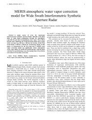
Figure 1. a, Location map showing the eastern part of the Bishop ignimbrite <strong>an</strong>d the positions of the 10 detailed<br />
sections along the Owens Gorge. b, Longitudinal section projected on the true left b<strong>an</strong>k, down the line of the Owens<br />
Gorge, showing the topographic relief of the valley <strong>an</strong>d the gorge walls, main ignimbrite packages (from Wilson <strong>an</strong>d<br />
Hildreth 1997; see also fig. 5), <strong>an</strong>d locations of the density sections. Note that the presence of Ig2Ec on the gorge<br />
rim between sections E <strong>an</strong>d F shows that the thinning over the basement high of older rocks of Ig2Ea <strong>an</strong>d Ig2Eb is<br />
a primary feature <strong>an</strong>d not due to subsequent erosion.
656 C. J. N. WILSON AND W. HILDRETH<br />
Table 1. Summary Stratigraphy of the Bishop Tuff in the Area East of Long Valley Caldera Discussed in This Article<br />
<strong>Ignimbrite</strong> unit Fall unit(s) Notes (ignimbrite)<br />
Ig2Ec F9 185% rhyolite in lithic component<br />
Ig2Eb F9 30%–70%<br />
Ig2Ea Later F8–F9 !20%<br />
Onset of Glass Mountain rhyolite in lithic fraction; incoming of pyroxene-bearing pumice<br />
Ig1Eb F6–earlier F8<br />
Fall horizon (part F6)<br />
Lithic poorer<br />
Ig1Ea Later F2–F6<br />
Fall horizon (F1–earlier F2)<br />
Lithic richer<br />
Note. After Wilson <strong>an</strong>d Hildreth (1997).<br />
proach will become inaccurate for deposits in<br />
which postemplacement diagenetic cementation or<br />
leaching has occurred, <strong>an</strong>d fiamme measurements<br />
may then be the only route to mapping variations<br />
in welding intensity (Roberts <strong>an</strong>d Sidd<strong>an</strong>s 1971; Peterson<br />
1979).<br />
Bishop Tuff Stratigraphic Background<br />
The 0.76 Ma Bishop Tuff consists of two components:<br />
a Plini<strong>an</strong> pumice fall deposit that occurs below,<br />
<strong>an</strong>d interbedded within, a nonwelded to<br />
densely welded ignimbrite (Wilson <strong>an</strong>d Hildreth<br />
1997; table 1). The fall deposit is exposed east of<br />
the source <strong>an</strong>d is divided into nine units (F1–F9)<br />
correlated by bedding <strong>an</strong>d grain-size characteristics<br />
<strong>an</strong>d lithic components (Wilson <strong>an</strong>d Hildreth 1997).<br />
The ignimbrite is well exposed along the walls of<br />
the Owens River valley, the Owens Gorge, <strong>an</strong>d the<br />
Chalk Bluffs escarpment (fig. 1), <strong>an</strong>d material r<strong>an</strong>ging<br />
from nonwelded through densely welded is<br />
widely exposed (Sherid<strong>an</strong> 1970; Rag<strong>an</strong> <strong>an</strong>d Sherid<strong>an</strong><br />
1972; Sherid<strong>an</strong> <strong>an</strong>d Rag<strong>an</strong> 1976).<br />
Our work (Wilson <strong>an</strong>d Hildreth 1997) has developed<br />
ways of subdividing the Bishop ignimbrite<br />
into stratigraphically m<strong>an</strong>ageable units. Clearly defined<br />
flow unit boundaries are scarce in the ignimbrite<br />
in general, <strong>an</strong>d so we introduced the concept<br />
of the eruptive package to encompass ignimbrite<br />
with broadly similar components <strong>an</strong>d lithological<br />
characteristics (but independent of welding zonation),<br />
that was emplaced as multiple pulses or flows<br />
over a definable stratigraphic interval (table 1). In<br />
the Owens Gorge <strong>an</strong>d other areas of the eastern<br />
Bishop Tuff, flow unit boundaries occur in three<br />
main circumst<strong>an</strong>ces: (1) in package Ig1Ea, where<br />
they are frequently demarcated by thin (centimeterto<br />
decimeter-thick) discontinuous-fall or hybridfall<br />
intercalations (fig. 2) or by truncations of degassing<br />
pipes (fig. 3); (2) in distal parts of Ig1Eb <strong>an</strong>d<br />
Ig2, where they are demarcated by the tops of concentration<br />
zones of coarser pumice (fig. 4) or occur<br />
as thin individual flow units intercalated within<br />
fall deposits (Wilson <strong>an</strong>d Hildreth 1997, their fig.<br />
9b); <strong>an</strong>d (3) where continuous decimeter-thick to<br />
meter-thick intercalations of fall material occur,<br />
defining the boundaries between packages Ig1Ea<br />
<strong>an</strong>d Ig1Eb, <strong>an</strong>d Ig1Eb <strong>an</strong>d Ig2Ea (Wilson <strong>an</strong>d Hildreth<br />
1997, their figs. 5, 9, <strong>an</strong>d 10).<br />
In the deposits discussed here, east of the caldera,<br />
earlier pyroxene-free ignimbrite (packages Ig1Ea,<br />
Ig1Eb) was emplaced synchronously with fall units<br />
F2 through all but uppermost F8, <strong>an</strong>d later pyroxenebearing<br />
ignimbrite (Ig2Ea–c) was emplaced synchronously<br />
with uppermost F8 <strong>an</strong>d F9 (table 1; Wilson<br />
<strong>an</strong>d Hildreth 1997). Some minor diachroneity<br />
is present in the Ig1E–Ig2E contact as the onset of<br />
Glass Mountain–derived rhyolite lithics occurs<br />
slightly below the time break at the F8–F9 contact.<br />
Where Ig1E <strong>an</strong>d Ig2E are in direct contact with no<br />
intervening fall material, the boundary between the<br />
two is placed at the onset of the Glass Mountain<br />
rhyolite lithics. The recognition that fall <strong>an</strong>d flow<br />
deposits were coevally emplaced allowed us to infer<br />
overall timings for emplacement of two packages;<br />
ca. 25 h for Ig1Ea <strong>an</strong>d ca. 36 h for Ig1Eb, <strong>an</strong>d hence<br />
to relate average accumulation rates to the presence<br />
or otherwise of flow unit boundaries that would<br />
indicate episodicity in deposition. Variations of<br />
welding in the tuff are superficially straightforward,<br />
with one zone of dense welding being present in<br />
the upper to middle reaches of the Owens Gorge,<br />
two zones in the middle to lower reaches, then a<br />
single zone along the Chalk Bluffs escarpment. Because<br />
of these variations, the Bishop was previously<br />
regarded as containing two cooling units (Sherid<strong>an</strong><br />
1968), which led Hildreth (1979) inappropriately to<br />
term it a composite sheet by the criteria of Smith<br />
(1960b).<br />
Sampling Strategies <strong>an</strong>d Methods<br />
To qu<strong>an</strong>tify the mech<strong>an</strong>ical structure of the ignimbrite,<br />
observations were made of <strong>an</strong>y intercalated
Journal of Geology ASSEMBLING AN IGNIMBRITE 657<br />
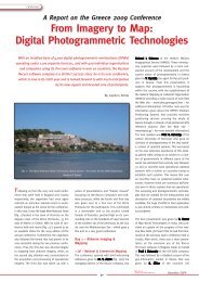
Figure 2. a, Photograph of nonwelded to sintered Ig1Ea<br />
at 546607 (grid reference to 100 m in the universal tr<strong>an</strong>sverse<br />
Mercator [UTM] metric grid) to show fall intercalations<br />
(arrowed) in Ig1Ea. Height of cliff is ∼27 m. b,<br />
Close-up view of fall-deposit intercalation at 546607.<br />
fall beds, flow unit boundaries, or stratification that<br />
could be interpreted to represent some kind of hiatus<br />
in deposition. With two exceptions (table 1),<br />
the intercalated fall beds are only centimeters to<br />
decimeters thick, are discontinuous, <strong>an</strong>d c<strong>an</strong>not<br />
consistently be used to regionally subdivide the ignimbrite<br />
packages. In the ignimbrite, measurements<br />
were also made of the maximum lengths of<br />
lithic <strong>an</strong>d pumice clasts or fiamme, <strong>an</strong>d the five<br />
largest values were averaged. The abund<strong>an</strong>ce of<br />
lithics was measured by counting the number of<br />
lithic fragments 15 mm across per square meter,<br />
<strong>an</strong>d their lithologic proportions tallied by counting<br />
rock types (Wilson <strong>an</strong>d Hildreth 1997).<br />
To qu<strong>an</strong>tify the thermal structure of the ignimbrite,<br />
observations of the welding state were made<br />
at m<strong>an</strong>y localities, using the degree of induration,<br />
presence or absence of a eutaxitic texture, <strong>an</strong>d the<br />
relative hardness of the rock. These observations<br />
were then calibrated against bulk density measurements<br />
(table 2) obtained from multiple sets of<br />
samples taken through the 10 detailed sections (A–<br />
J) along the Owens Gorge (fig. 1) <strong>an</strong>d were used to<br />
generate a 2-D profile of welding intensity along<br />
the gorge wall.<br />
Density measurements were made on samples<br />
collected from representative blocks or cored from<br />
typical matrix material, avoiding <strong>an</strong>y obvious local<br />
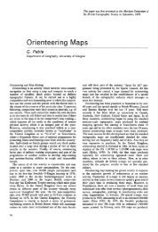
Figure 3. a, Photograph of flow-unit boundary (arrowed)<br />
in Ig1Ea at 521609, locally demarcated (b)bytruncated<br />
degassing segregation pipes.
658 C. J. N. WILSON AND W. HILDRETH<br />
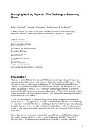
Figure 4. Photographs of flow units in (a) Ig1Eb in the Owens Gorge at 632466, defined by the tops of swarms of<br />
fiamme marking former pumice concentration zones, <strong>an</strong>d in (b) Ig2Ea at 790475, defined by pumice swarms.<br />
concentrations of lithic or pumice clasts that might<br />
skew the results. Lithic proportions in grain-size<br />
samples of representative ignimbrite from the<br />
Owens Gorge area are all !10 wt%, mostly !5 wt%,<br />
<strong>an</strong>d so the effects of lithics on the sample density<br />
have been neglected. Densities of coherent (sintered<br />
to densely welded) ignimbrite were determined<br />
on representative 300–1800-g blocks, using<br />
water displacement techniques (Archimedes’ principle)<br />
to determine block volumes, with specimens<br />
previously being saturated in water to eliminate<br />
ingress of water during measurement. Ten determinations<br />
were made on each sample, <strong>an</strong>d the resulting<br />
st<strong>an</strong>dard deviations on the density determinations<br />
r<strong>an</strong>ged between 0.001 <strong>an</strong>d 0.010 Mg/m 3 .<br />
Densities of nonwelded (sievable) ignimbrite were<br />
determined from single samples cored in the field<br />
using a carpenter’s brace <strong>an</strong>d bit to excavate a cylindrical<br />
hole of measurable volume (137–296 cm 3 ).<br />
The excavated material was caught in a bag for subsequent<br />
drying <strong>an</strong>d weighing to determine its density.<br />
At one point in section J, block <strong>an</strong>d cored samples<br />
could be obtained from the same level<br />
(everywhere else, the ignimbrite was either too indurated<br />
to excavate with the brace <strong>an</strong>d bit or too<br />
soft to be taken as a coherent block); density values<br />
are 1.262 0.002 (1 SD) Mg/m 3 <strong>an</strong>d 1.240 Mg/m 3<br />
for block <strong>an</strong>d core, respectively. The raw data set<br />
is available from the The Journal of Geology’s Data<br />
Depository free of charge upon request or as <strong>an</strong> Excel<br />
spreadsheet from C. J. N. Wilson.<br />
Mech<strong>an</strong>ical Structure of the Bishop <strong>Ignimbrite</strong><br />
Of the various parameters measured in the ignimbrite,<br />
variations in lithic sizes, numerical abund<strong>an</strong>ces,<br />
<strong>an</strong>d lithologies show up the mech<strong>an</strong>ical<br />
structure best (fig. 5). Coupled with observations of<br />
intercalations of the main fall deposit between<br />
Ig1Ea <strong>an</strong>d Ig1Eb <strong>an</strong>d between Ig1 <strong>an</strong>d Ig 2, these<br />
data show the large-scale cross-sectional structure<br />
of the ignimbrite down the line of the Owens River<br />
(i.e., approximately parallel to the inferred paleoflow<br />
direction) to be a series of offlapping or imbricate<br />
lenses. Internal subdivision of Ig1Eb is discernible<br />
on the basis of lithic counts (fig. 5),<br />
suggesting that the imbricate structure is also paralleled<br />
by growth of the individual packages. Each<br />
main package in turn reaches farther from the<br />
source, with the exception of Ig2Ec, which is poorly<br />
developed in this area (Wilson <strong>an</strong>d Hildreth 1997,<br />
their fig. 12). In a section at 830529 (grid reference<br />
to 100 m in the universal tr<strong>an</strong>sverse Mercator<br />
[UTM] metric grid) on the slopes of the White
Journal of Geology ASSEMBLING AN IGNIMBRITE 659<br />
Table 2. Summary of Field Descriptive Terms Used for Welding Textures in the Bishop <strong>Ignimbrite</strong><br />
Welding term Nature of deposit<br />
Density<br />
(Mg/m3 )<br />
Densely welded Strong eutaxitic texture, dark color if glassy 1ca. 2.00<br />
Moderately welded Clear eutaxitic texture, still relatively soft 1.74–2.00<br />
Poorly welded Some pumice flattening, highly porous <strong>an</strong>d soft 1.49–1.81<br />
Sintered Coherent; requires hammer to fracture; no eutaxitic texture 1.22–1.57<br />
Nonwelded Noncoherent; c<strong>an</strong> be disaggregated between fingers 1.09–1.47<br />
Note. Correlated with density measurements reported in this article.<br />
Mountains east of the Owens Gorge area, a single<br />
centimeter-scale “swash”-like bed of Ig2Eb flow<br />
material occurs within thick F9 fall deposits, at a<br />
stratigraphic level that implies that package Ig2Eb<br />
traveled the farthest of all to the east of the source.<br />
The causes of this offlapping structure in the ignimbrite<br />
c<strong>an</strong>not be related simply to increasing velocities<br />
of the parental flows, since lithic sizes (<strong>an</strong>d<br />
hence inferred velocities <strong>an</strong>d flow-carrying capacities)<br />
in Ig2E are smaller th<strong>an</strong> in Ig1Eb (fig. 5). Instead,<br />
two other factors were probably import<strong>an</strong>t.<br />
First, earlier flows of Ig1Ea <strong>an</strong>d early Ig1Eb would<br />
have ponded in nearer-source low-lying areas,<br />
whereas later flows could travel over a smoother<br />
surface of subdued topographic relief. Second, the<br />
earlier flows are poorer in fine ash-grade material<br />
(fig. 6), regardless of dist<strong>an</strong>ce from the source, <strong>an</strong>d<br />
are thus likely to have deaerated more rapidly <strong>an</strong>d<br />
consequently to have been less mobile (Roche et<br />
al. 2002).<br />
Ch<strong>an</strong>ges in the parameters illustrated in figure 5<br />
serve to highlight two points. First, within Ig1Ea<br />
<strong>an</strong>d Ig1Eb, there do not appear to be major hiatuses<br />
between material separated by flow-unit boundaries<br />
(apart from ch<strong>an</strong>ges in pumice or fiamme abund<strong>an</strong>ce<br />
that define the boundary itself, e.g., fig. 4) or<br />
by fall-deposit intercalations. This implies that the<br />
overall ch<strong>an</strong>ges in lithic sizes <strong>an</strong>d abund<strong>an</strong>ces in<br />
Ig1E were controlled by gradual variations in the<br />
source area, such that flows separated by minutes<br />
to hours share broadly similar characteristics. Second,<br />
at the contact between Ig1E <strong>an</strong>d either Ig2Ea<br />
or Ig2Eb, there are locally abrupt ch<strong>an</strong>ges in measured<br />
parameters (especially the count percentage<br />
of rhyolite in the lithic fraction, Wilson <strong>an</strong>d Hildreth<br />
1997) over dist<strong>an</strong>ces of !0.5 m, such as at<br />
section G (figs. 1, 5), but with no sign of <strong>an</strong>y discontinuity<br />
to reflect <strong>an</strong>y time break or hiatus in<br />
ignimbrite deposition. This is so even though the<br />
presence farther down-valley of F9 fall deposits<br />
along this contact (Wilson <strong>an</strong>d Hildreth 1997, their<br />
fig. 10) demonstrates unequivocally the presence of<br />
a signific<strong>an</strong>t time break. The possibility that ignimbrite<br />
deposition was continuous at section G<br />
but discontinuous down-valley is precluded by the<br />
presence of Ig2Ea down-valley between fall F9 <strong>an</strong>d<br />
Ig2Eb (fig. 5); both F9 <strong>an</strong>d Ig2Ea are absent at section<br />
G. Thus, in the material exposed in the Owens<br />
Gorge, some parts of the Bishop ignimbrite show<br />
that a demonstrable time break may not be accomp<strong>an</strong>ied<br />
by signific<strong>an</strong>t ch<strong>an</strong>ges in the properties of<br />
the ignimbrite (first point above), whereas other<br />
parts show that clearly defined ch<strong>an</strong>ges in ignimbrite<br />
properties may lack <strong>an</strong>y evidence for a signific<strong>an</strong>t<br />
time break, even though such a break c<strong>an</strong><br />
be shown elsewhere to have occurred (second point<br />
above).<br />
<strong>Thermal</strong> Structure of the Bishop <strong>Ignimbrite</strong><br />
Density values measured at each section are plotted<br />
in figures 7–10 as vertical profiles linked to the<br />
horizontal profile along the line of the Owens<br />
Gorge, with independently determined stratigraphic<br />
units <strong>an</strong>d horizons plotted for comparison.<br />
The overall welding state of the ignimbrite along<br />
the walls of the gorge is shown in figure 11. We<br />
draw attention to five features from our data.<br />
1. We recognize four density, <strong>an</strong>d hence welding,<br />
maxima (labeled Zones a through d, from oldest to<br />
youngest). Continuity of these zones between sections<br />
has been ensured by tracing the welding zones<br />
(<strong>an</strong>d stratigraphic marker pl<strong>an</strong>es) along the wellexposed<br />
walls of the Owens River valley. The combination<br />
of stratigraphic controls <strong>an</strong>d good exposure<br />
demonstrates that these four welding zones<br />
are not equally prominent at <strong>an</strong>y one section, <strong>an</strong>d<br />
that the ignimbrite hosting Zones b through d<br />
forms <strong>an</strong> imbricate, overlapping succession, such<br />
that the most prominent development of each<br />
package <strong>an</strong>d its associated welding zone occurs successively<br />
farther from the source (fig. 11). Each<br />
welding zone is developed in a stratigraphically<br />
confined part of the ignimbrite: (a) Ig1Ea; (b) lower<br />
Ig1Eb; (c) upper Ig1Eb; (d) upper Ig2Eb, <strong>an</strong>d thus the<br />
most heat-retentive (i.e., highest emplacement<br />
temperature) material was emplaced to form these<br />
parts of the ignimbrite at certain times. The development<br />
of welding then depends on the local<br />
thickness of each package <strong>an</strong>d the development of
660 C. J. N. WILSON AND W. HILDRETH<br />
Figure 5. Series of longitudinal sections down the line of the Owens Gorge projected on the true left side to show<br />
the data used to define the ignimbrite packages. a, Maximum lithic size (average lengths of the five largest clasts)<br />
in millimeters. b, Numbers of 15-mm-long lithic clasts per square meter. c, The count percent of Glass Mountain<br />
rhyolite in the 15-mm lithic fraction (measurement techniques after Wilson <strong>an</strong>d Hildreth 1997). The dotted line in<br />
b is a contour of 50 lithics/m 2 used to separate lower <strong>an</strong>d upper parts of Ig1Eb <strong>an</strong>d their associated welding zones<br />
(see fig. 11). Note that the approximate paleoflow direction is parallel to the gorge, <strong>an</strong>d so dist<strong>an</strong>ces down the gorge<br />
approximate to radial dist<strong>an</strong>ces from the source.<br />
additional stresses due to subsequent syneruptive<br />
lithostatic load; for example, Zone c attains lower<br />
maximum densities in the upper Owens Gorge (fig.<br />
7, section A) because it was thinner <strong>an</strong>d was buried<br />
under lesser thicknesses of Ig2E material there<br />
compared with the middle <strong>an</strong>d lower reaches of the<br />
gorge.<br />
2. The upper Owens Gorge (sections A–C) is the<br />
only area where all four zones are exposed in proximity,<br />
<strong>an</strong>d Zone b is the best developed. Zone a is<br />
represented by incipient pumice flattening <strong>an</strong>d is<br />
exposed only over a limited area where downcutting<br />
to the east by the Owens River intersects a<br />
westward-thickening wedge of Ig1Ea material.<br />
Zones b <strong>an</strong>d c, both in Ig1Eb, are separately demarcated<br />
in this area by at most a slight reduction<br />
in density (e.g., section A). However, the stratigraphic<br />
control given by variations in numerical<br />
abund<strong>an</strong>ces of lithic fragments (particularly the 50<br />
lithics/m 2 contour; fig. 5) show that the thick<br />
welded Ig1Eb deposits in the middle Owens Gorge<br />
(e.g., sections F <strong>an</strong>d G) correlate only with Zone c<br />
<strong>an</strong>d that material equivalent to Zone b in the upper<br />
parts of the gorge forms only a nonwelded to poorly<br />
welded basal zone to the ignimbrite down-valley<br />
from the prominent high in the basement rocks (fig.<br />
11).<br />
3. In the middle to lower Owens Gorge (sections<br />
G–I), there is a pronounced density minimum between<br />
the maxima of Zones c <strong>an</strong>d d (figs. 7–9), but<br />
the location of this minimum is at a level of no<br />
special stratigraphic signific<strong>an</strong>ce. The basal parts
Journal of Geology ASSEMBLING AN IGNIMBRITE 661<br />
Figure 6. Plot of the contents of !1/16-mm material<br />
versus the me<strong>an</strong> grain size (M z of Folk <strong>an</strong>d Ward 1957)<br />
in sieved samples collected from the four main packages<br />
of Bishop ignimbrite along, or close to, the Owens Gorge.<br />
Samples represent both proximal <strong>an</strong>d distal material in<br />
all packages <strong>an</strong>d also bracket stratigraphically material<br />
that is representative of the densest-welded ignimbrite.<br />
Note the clear distinction in !1/16-mm ash contents between<br />
Ig1E <strong>an</strong>d Ig2E samples.<br />
of Ig2Ea show <strong>an</strong> upward diminishing welding intensity<br />
at sections H (fig. 9) <strong>an</strong>d I, yet at all sites<br />
in the Bishop Tuff where Ig2Ea overlies solely fall<br />
deposits, it is nonwelded. We infer that the emplacement<br />
temperature of Ig2Ea in itself was insufficient<br />
to cause welding, but where it was deposited<br />
on still-hot Ig1Eb, the residual heat from<br />
the underlying deposit was sufficient to cause<br />
“back-welding” of Ig2Ea under the lithostatic stress<br />
of later-deposited material. The density minimum<br />
in the middle Owens Gorge is poorly defined at<br />
sections F <strong>an</strong>d G, largely because Zone d is less<br />
well developed th<strong>an</strong> farther down-gorge as a consequence<br />
of the lesser overlying thickness of Ig2Eb.<br />
4. Wide fluctuations in density are seen in the<br />
nonwelded to sintered material of section J, <strong>an</strong>d the<br />
lowest in situ densities are actually in sintered, not<br />
nonwelded, material (fig. 10). Grain size <strong>an</strong>d component<br />
characteristics of the nonwelded material<br />
ch<strong>an</strong>ge very little, <strong>an</strong>d so the density fluctuations<br />
are not due to variations in either dense (lithic,<br />
crystal) or fine-ash (!1/16 mm) components (fig.<br />
10). We interpret the density values to reflect the<br />
locking in by the sintering processes of bulk densities<br />
at a stage when compaction of the ignimbrite<br />
from its newly emplaced state was incomplete (i.e.,<br />
while the deposit was stationary but still hot <strong>an</strong>d<br />
somewhat exp<strong>an</strong>ded). We infer that nonwelded material<br />
could continue to compact locally by intergrain<br />
movements in response to load stresses (probably<br />
augmented by earthquake-induced ground<br />
shaking in this tectonically active area; Pinter<br />
1995), whereas the structural framework induced<br />
by sintering could resist further compaction. Thus<br />
the mathematically convenient, extrapolated density<br />
value of 1.0 Mg/m 3 adopted by Rag<strong>an</strong> <strong>an</strong>d Sherid<strong>an</strong><br />
(1972) <strong>an</strong>d Sherid<strong>an</strong> <strong>an</strong>d Rag<strong>an</strong> (1976) for nonwelded<br />
material to calculate compactional strain<br />
in ignimbrites <strong>an</strong>d infer the position of the original<br />
ignimbrite surface is not supported by our data.<br />
5. An import<strong>an</strong>t aspect of interpreting the welding<br />
<strong>an</strong>d thermal history of <strong>an</strong> ignimbrite is identifying<br />
whether devitrification <strong>an</strong>d vapor-phase<br />
crystallization follow on from the welding compaction,<br />
or interrupt <strong>an</strong>d terminate it. In several<br />
places in the sections measured, there are sharp<br />
ch<strong>an</strong>ges from vitric to nonvitric tuff, <strong>an</strong>d samples<br />
collected in proximity from each type of material<br />
show no major differences in density (fig. 12).<br />
We thus infer that welding densification was effectively<br />
completed before devitrification <strong>an</strong>d/or<br />
vapor-phase crystallization <strong>an</strong>d that the latter two<br />
processes did not act to prematurely halt densification<br />
(cf. item 4, above). Since the densities of the<br />
minerals created by devitrification are greater th<strong>an</strong><br />
those for the vitric phase, a lack of systematically<br />
increased density in devitrified material must<br />
therefore be accomp<strong>an</strong>ied by some increase in the<br />
microscale porosity of the rock.<br />
Three prominent zones of vapor-phase crystallization<br />
are also present in parts of the Bishop ignimbrite<br />
described here: (1) s<strong>an</strong>dwiched between<br />
the most strongly welded portions of Zones b <strong>an</strong>d<br />
c in the upper Owens Gorge, (2) s<strong>an</strong>dwiched between<br />
the most strongly welded portions of Zones<br />
c <strong>an</strong>d d in the middle to lower Owens Gorge (fig.<br />
10; Holt <strong>an</strong>d Taylor 1998), <strong>an</strong>d (3) above Zone d<br />
in the lower Owens Gorge. In similar fashion to<br />
the zones of denser welding that they overlie, each<br />
vapor-phase crystallization zone becomes successively<br />
most prominent in sections along the horizontal<br />
profile of the Owens Gorge. Parallel to variations<br />
in the welding profiles, vapor-phase<br />
crystallization is prominent in Ig2Ea <strong>an</strong>d lower<br />
Ig2Eb only where they overlie welded <strong>an</strong>d devitrified<br />
Ig1Eb (i.e., Zone c; fig. 9); in contrast, where<br />
they overlie vitric welded ignimbrite or fall deposits,<br />
no signific<strong>an</strong>t vapor-phase crystallization is<br />
seen (fig. 10). Thus the regional distribution of areas<br />
of intense fumarolic alteration reported by Sherid<strong>an</strong><br />
(1970) closely reflect the alteration of Ig2E
Figure 7. Density profiles through the Bishop ignimbrite at seven of the 10 sections (A–F, I) shown in figure 1. For<br />
sections G, H, <strong>an</strong>d J, see figures 8–10, respectively. In each profile, filled circles represent data from nonwelded<br />
(sievable) tuff, <strong>an</strong>d filled squares, data from coherent blocks of tuff.
Journal of Geology ASSEMBLING AN IGNIMBRITE 663<br />
Figure 8. View of east wall of the Owens Gorge at grid reference 624490 showing position of section G, selected<br />
data on densities <strong>an</strong>d lithic lithologies, <strong>an</strong>d positions of welding zones <strong>an</strong>d package boundaries. Symbols are as in<br />
figure 7.<br />
above largely buried f<strong>an</strong>s of Ig1Eb (welding Zone c)<br />
that accumulated down the paleodrainages of the<br />
Owens Gorge <strong>an</strong>d Chidago C<strong>an</strong>yon (Wilson <strong>an</strong>d<br />
Hildreth 1997, their fig. 6).<br />
Discussion<br />
Here we review usage of the terms “flow unit” <strong>an</strong>d<br />
“cooling unit” in the light of our Bishop Tuff data.<br />
In doing this, we emphasize a key factor, namely,<br />
that although these terms remain useful for descriptive<br />
purposes, their qu<strong>an</strong>titative application in<br />
interpreting emplacement histories of ignimbrites<br />
is problematic in several import<strong>an</strong>t respects. To use<br />
either term in a nonsimplistic way requires recognition<br />
<strong>an</strong>d acknowledgment of implicit complexities<br />
that have been widely ignored.<br />
Mech<strong>an</strong>ical <strong>Building</strong> <strong>Blocks</strong>: Flow Units. Recognition<br />
of flow units in ignimbrites fundamentally<br />
depends on recognizing flow-unit boundaries,<br />
which in turn indicate (to some extent) a hiatus in<br />
deposition. Note, however, that the inverse does<br />
not hold, that is, not all discontinuities need represent<br />
flow-unit boundaries. Some discontinuities<br />
may arise, for example, through irregular rates of<br />
deposition at the base of a single short-lived flow<br />
(e.g., layering in the Taupo ignimbrite veneer deposit;<br />
Wilson 1985). The nature of flow-unit boundaries<br />
c<strong>an</strong> be highly variable, including the presence<br />
of material of contrasting depositional mech<strong>an</strong>isms<br />
(especially fall material, that would have taken a<br />
finite time to accumulate; fig. 2; Wilson <strong>an</strong>d Hildreth<br />
1997), the presence of <strong>an</strong> inverse-graded layer<br />
2a (Sparks et al. 1973), or truncation of such features<br />
as degassing pipes or pumice concentration<br />
zones in the underlying material (figs. 3, 4). From<br />
this, two corollaries arise.<br />
First, whether or not a flow-unit boundary is seen<br />
depends primarily on the state of the earlierdeposited<br />
material. If the earlier material was unconsolidated,<br />
then shearing at the base of the later<br />
flow may cause mixing of the earlier <strong>an</strong>d newly<br />
depositing material to obscure <strong>an</strong>y contact; unless<br />
there is some contrast in properties (e.g., grain size<br />
or composition), no flow-unit boundary <strong>an</strong>d hence<br />
no evidence for a hiatus may be present. Processes<br />
that would enh<strong>an</strong>ce consolidation of the substrate<br />
include the following, each of which may act on<br />
different time scales: the presence of abund<strong>an</strong>t<br />
coarse clasts that would supply a rigid framework<br />
(e.g., fig. 4a); degassing <strong>an</strong>d compaction of nonwelded<br />
material; welding-induced cohesion; or deposition<br />
of fall material. The second corollary follows<br />
from this, that there is a spectrum of possible<br />
time breaks, reflected by boundaries of some sort,<br />
within the course of emplacement of <strong>an</strong>y ignimbrite,<br />
from seconds up to (conceivably as long as)<br />
months. Thus, depending on local circumst<strong>an</strong>ces,
664 C. J. N. WILSON AND W. HILDRETH<br />
Figure 9. View of east wall of the Owens Gorge at grid reference 633468 showing position of section H, selected<br />
data on densities <strong>an</strong>d lithic lithologies, <strong>an</strong>d positions of welding zones <strong>an</strong>d package boundaries. See Wilson <strong>an</strong>d<br />
Hildreth (1997, their fig. 10) for a closer view of the fall bed contact from this section. Symbols are as in figure 7.<br />
a hiatus between separate flow units (identified as<br />
such here by differing characteristics) may or may<br />
not result in a visible flow-unit boundary.<br />
Fisher (1966) <strong>an</strong>d Br<strong>an</strong>ney <strong>an</strong>d Kokelaar (1992,<br />
1997) suggested that thick ignimbrite sequences<br />
with no apparent flow-unit boundaries may have accumulated<br />
progressively in a continuous fashion<br />
rather th<strong>an</strong> being the products of a single flow or of<br />
piecemeal accumulation from a number of discrete<br />
flows. Our observations <strong>an</strong>d data for the Bishop Tuff<br />
imply, however, that ignimbrite with no visible<br />
flow-unit boundaries c<strong>an</strong> result from emplacement<br />
of multiple flows separated by time breaks. In other<br />
words, a lack of flow-unit boundaries is not diagnostic<br />
of continuous, progressive aggradation. The<br />
clearest example of this is at section G, where Ig2Eb<br />
overlies Ig1Eb with no visible boundary in the field,<br />
the contact being demarcated to !0.5 m by the incoming<br />
upward of Glass Mountain–derived rhyolite<br />
lithic fragments (figs. 5, 8). Elsewhere in the Bishop<br />
ignimbrite (e.g., sections H <strong>an</strong>d I, fig. 10; also Wilson<br />
<strong>an</strong>d Hildreth 1997, their fig. 10), fall material<br />
<strong>an</strong>d Ig2Ea were deposited at this horizon, indicating<br />
a time gap of hours to tens of hours between ignimbrite<br />
packages Ig1Eb <strong>an</strong>d Ig2Eb. We thus conclude<br />
that the presence of a flow-unit boundary<br />
does indicate a hiatus in deposition but that the<br />
reverse is not necessarily true, <strong>an</strong>d that a lack of<br />
flow-unit boundaries, in the absence of other evidence,<br />
c<strong>an</strong>not be taken to indicate that accumu-<br />
lation was continuous (cf. Br<strong>an</strong>ney <strong>an</strong>d Kokelaar<br />
1997).<br />
<strong>Thermal</strong> <strong>Building</strong> <strong>Blocks</strong>: Cooling Units. In the definitions<br />
<strong>an</strong>d illustrative examples of Smith (1960b,<br />
especially pl. 20), it is implicit that the primary<br />
me<strong>an</strong>s whereby a simple cooling unit is recognized<br />
is the ideality of its patterns of zonation in welding,<br />
devitrification, <strong>an</strong>d vapor-phase recrystallization.<br />
The term “compound cooling unit” is then automatically<br />
applied to <strong>an</strong>y deposit that shows “pronounced<br />
deviations” from this pattern (Smith<br />
1960b, p. 157) but c<strong>an</strong> still be considered to have<br />
accumulated rapidly enough for the whole rock<br />
body to cool as one (i.e., to be a single cooling unit).<br />
However, these definitions, as well as the concept<br />
of a composite sheet, are problematic in several<br />
respects:<br />
1. As the perceived zonations for a single cooling<br />
unit c<strong>an</strong> vary so widely (Smith 1960a, 1960b), the<br />
criterion for “pronounced deviations” <strong>an</strong>d hence<br />
the simple versus compound distinction c<strong>an</strong> be<br />
given only in qualitative terms.<br />
2. Even given a simple welding <strong>an</strong>d alteration<br />
profile, turning such a description into interpretation<br />
of the time-temperature relationships of the<br />
deposited material is not always possible. For example,<br />
several workers have inferred (e.g., Christi<strong>an</strong>sen<br />
1979) or assumed (Riehle 1973; Riehle et<br />
al. 1995) that a simple cooling unit is effectively<br />
isothermal on emplacement, consistent with rapid
Journal of Geology ASSEMBLING AN IGNIMBRITE 665<br />
Figure 10. View of Chalk Bluffs at grid reference 733421. Section J was measured from the fall deposit up to the<br />
“cryptic ledge” (a zone of barely sintered material that marks the approximate contact between Ig2Ea <strong>an</strong>d Ig2Eb) on<br />
this face <strong>an</strong>d above this level in a slip scar 100 m farther east. Selected grain size <strong>an</strong>d componentry data (the latter<br />
measured down to 1/16 mm, with !1/16 mm material assumed to be vitric ash) from material taken at the same<br />
point as the density samples are shown to compare with the density variations. Symbols are as in figure 7.<br />
accumulation <strong>an</strong>d simple patterns of welding <strong>an</strong>d<br />
alteration. If, however, a simple cooling unit is built<br />
up progressively (whether continuously or not),<br />
then the emplacement temperatures may have deviated<br />
signific<strong>an</strong>tly from uniform during accumulation.<br />
For example, the basal <strong>an</strong>d topmost materials<br />
may have been cooler <strong>an</strong>d the interior hotter,<br />
or increasing magma temperatures in a zoned package<br />
may influence emplacement temperatures, yet<br />
the welding <strong>an</strong>d alteration zonation could, in principle,<br />
be simple in the sense used by Smith.<br />
3. The distinction between single <strong>an</strong>d multiple<br />
cooling units is valid in principle but may be problematic<br />
to apply in practice. We label the Bishop<br />
ignimbrite in the Owens Gorge a single cooling<br />
unit because of evidence from the density profiles<br />
that the earlier parts of the ignimbrite (Ig1E) were<br />
still hot when later parts (Ig2E) accumulated. For<br />
example, welding Zone c in Ig1Eb was still hot<br />
enough when buried by Ig2Ea <strong>an</strong>d/or Ig2Eb to have<br />
caused welding in the immediately overlying Ig2<br />
material (sections G–I; figs. 7–9) even though that
666 C. J. N. WILSON AND W. HILDRETH<br />
Figure 11. Longitudinal section down the line of the Owens Gorge projected on the true left side showing the<br />
overall welding structure of the ignimbrite. Density data from the 10 profiles (figs. 7–10) were combined with sparse<br />
point measurements <strong>an</strong>d then matched to field observations at numerous sites along the gorge walls using the<br />
calibration between density, rock texture, <strong>an</strong>d welding given in table 2. The dotted line is the 50 lithics/m 2 contour<br />
derived from lithic numerical abund<strong>an</strong>ce data (fig. 5b); note how this contour serves to demarcate welding Zone b<br />
(best developed at sections A <strong>an</strong>d B) <strong>an</strong>d Zone c (best developed down-gorge from section E), with <strong>an</strong> overlap around<br />
sections C <strong>an</strong>d D.<br />
material was insufficiently hot to weld where it<br />
overlay a cold substrate (section J; fig. 10). We thus<br />
disagree with Sherid<strong>an</strong> (1968), who considered that<br />
there were two cooling units in the same area as<br />
sections G–I, implying that the Bishop ignimbrite<br />
is a composite sheet. In general, we suggest from<br />
our data that only in circumst<strong>an</strong>ces where the earlier<br />
unit was effectively “cold,” that is, unable to<br />
influence the welding profile or alteration state of<br />
the later unit, might the density minimum between<br />
two zones of greater welding actually coincide<br />
with the chronostratigraphic boundary between<br />
the two bodies of material. Only under such<br />
circumst<strong>an</strong>ces could the two bodies then be considered<br />
as separate cooling units. In the case of the<br />
Bishop Tuff, lateral ch<strong>an</strong>ges in welding down the<br />
Owens Gorge from areas with only one maximum<br />
in welding intensity (e.g., section E) to those with<br />
two welding maxima do not reflect splitting of<br />
welding zones (from “simple” to “compound”) or<br />
of cooling units (from one to two), but instead result<br />
from differing development of separate welding<br />
maxima as successive packages of host material become<br />
thickest in turn down-gorge.<br />
Thus, in documenting ignimbrites even as young<br />
<strong>an</strong>d clearly exposed as the Bishop, problems arise<br />
with the qu<strong>an</strong>titative interpretation of the cooling<br />
unit concept. Although the original concepts have<br />
demonstrated their value as a descriptive framework<br />
(e.g., Christi<strong>an</strong>sen 1979, <strong>an</strong>d references<br />
therein), interpretative application of the concept<br />
to infer the timings <strong>an</strong>d temperatures of accumulating<br />
ignimbrite material is fraught with problems.<br />
These arise primarily because the welding intensity<br />
(<strong>an</strong>d <strong>an</strong>y consequent devitrification <strong>an</strong>d vaporphase<br />
alteration) depends on several properties of<br />
the deposited material, including variations in (1)<br />
emplacement temperatures (themselves complexly<br />
related to eruption composition, heat losses during<br />
tr<strong>an</strong>sport, <strong>an</strong>d admixture of lithic material), (2) juvenile<br />
compositions, (3) residual volatile contents,<br />
<strong>an</strong>d (4) load stresses. However, even when such factors<br />
as juvenile composition <strong>an</strong>d residual volatiles<br />
are accounted for (or are assumed to be uniform)<br />
in a particular deposit, a given density/welding profile<br />
has a nonunique relationship to its emplacement<br />
temperature profile because the individual<br />
mech<strong>an</strong>ical building blocks (flow units or emplacement<br />
pulses) <strong>an</strong>d their associated temperatures c<strong>an</strong>not<br />
necessarily be uniquely defined, even in <strong>an</strong> ostensibly<br />
simple cooling unit.<br />
Furthermore, although the descriptive distinc-
Journal of Geology ASSEMBLING AN IGNIMBRITE 667<br />
Figure 12. Plot of density data from five pairs of samples<br />
from across vitric to nonvitric boundaries in portions<br />
of the ignimbrite that show minimal background gradients<br />
in density. We use these data to infer that densification<br />
of the ignimbrite by welding processes acting on<br />
the viscous vitric component had largely or completely<br />
ceased by the time crystallization due to devitrification<br />
or vapor-phase alteration occurred.<br />
tion between simple <strong>an</strong>d compound cooling units<br />
is in principle straightforwardly based on the patterns<br />
of welding <strong>an</strong>d crystallization in the rock<br />
mass, interpreting the genetic <strong>an</strong>d chronologic signific<strong>an</strong>ce<br />
of a compound cooling unit profile may<br />
be complex. First, <strong>an</strong>d most straightforwardly, compound<br />
cooling profiles that show only one welding<br />
maximum that occurs toward the top of the ignimbrite<br />
(e.g., section J in the Bishop; fig. 10) are often<br />
interpreted as due to the superposition of increasingly<br />
hotter material with no perceived time breaks<br />
(Lipm<strong>an</strong> et al. 1966; Br<strong>an</strong>ney <strong>an</strong>d Kokelaar 1997).<br />
However, although the welding zonation is compound<br />
(according to Smith 1960b), the emplacement<br />
dynamics of the deposit may not differ in <strong>an</strong>y<br />
respect from those of a simple cooling unit, other<br />
th<strong>an</strong> in the emplaced material becoming hotter<br />
with time. Second, compound cooling units that<br />
have more th<strong>an</strong> one welding maximum are widely<br />
interpreted as reflecting emplacement at intervals<br />
of time sufficient to allow partial cooling of the<br />
earlier material (Christi<strong>an</strong>sen 1979, p. 29; Riehle et<br />
al. 1995), unless evidence for other sources of cool-<br />
ing, particularly the incorporation of cold lithic material,<br />
is present (Lipm<strong>an</strong> et al. 1989, p. 340).<br />
From our work, we infer that there are only two<br />
extended breaks in emplacement of the Bishop ignimbrite,<br />
represented by the F6 fall material separating<br />
Ig1Ea <strong>an</strong>d Ig1Eb (sections A–C), <strong>an</strong>d the F8–<br />
F9 fall material between Ig1Eb <strong>an</strong>d Ig2Ea (sections<br />
H <strong>an</strong>d I). Using fall-accumulation rate estimates<br />
(Wilson <strong>an</strong>d Hildreth 1997), these time breaks are<br />
estimated as 5–10 h for the former <strong>an</strong>d 3 h for the<br />
latter (with <strong>an</strong> additional but short period represented<br />
by the settling out of ash <strong>an</strong>d trivial erosion<br />
[at one site only] at the level of the F8–F9 contact).<br />
In Ig1Ea, other thin fall horizons <strong>an</strong>d flow-unit<br />
boundaries are seen (fig. 2), but the time breaks are<br />
by inference !3 h. None of these time breaks in<br />
themselves is adequate to permit signific<strong>an</strong>t cooling<br />
of the ignimbrite packages (Riehle 1973), <strong>an</strong>d<br />
no discontinuity in density is seen across <strong>an</strong>y of<br />
these depositional breaks. Thus the whole accumulation<br />
of Bishop ignimbrite in this sector represents<br />
a single emplacement unit from the perspective<br />
of its thermal history; that is, it is a single,<br />
compound cooling unit (Smith 1960b).<br />
However, the density minima in sections A–J,<br />
although defining compound cooling, do not coincide<br />
with or represent time breaks at all. If one<br />
accepts that the prime controls on welding intensity<br />
in the interior of the Bishop ignimbrite are emplacement<br />
temperatures <strong>an</strong>d load stresses, <strong>an</strong>d that<br />
load stresses diminish systematically upward, the<br />
closely spaced vertical density variations must then<br />
reflect differing emplacement temperatures with<br />
time. For example, the lower part of Ig2Eb <strong>an</strong>d all<br />
of Ig2Ea were emplaced at signific<strong>an</strong>tly cooler temperatures,<br />
in the latter case insufficient to induce<br />
welding where overlying a fall-deposit substrate.<br />
Our data imply that models presented by Riehle<br />
(1973) <strong>an</strong>d Riehle et al. (1995) for inferring the emplacement<br />
temperature of simple or compound,<br />
single or multiple cooling units are thus limited in<br />
two respects. First, as discussed earlier, a given density<br />
profile in a real deposit (even <strong>an</strong> apparently<br />
simple cooling unit) c<strong>an</strong> result from a number of<br />
possible combinations of increments of material (or<br />
flow units) with nonuniform temperatures. To<br />
match a real-world density profile of a simple cooling<br />
unit with a given inferred emplacement temperature<br />
thus requires <strong>an</strong> assumption of isothermal<br />
emplacement. Second, in a single compound cooling<br />
unit such as the Bishop ignimbrite, we c<strong>an</strong> show<br />
that the position of the density minimum between<br />
two zones of more strongly welded ignimbrite does<br />
not coincide with <strong>an</strong>y time break, such breaks elsewhere<br />
being unequivocally flagged by interbedded
668 C. J. N. WILSON AND W. HILDRETH<br />
fall material (e.g., sections H <strong>an</strong>d I) or inferred from<br />
sharp ch<strong>an</strong>ges in ignimbrite lithology (e.g., sections<br />
F <strong>an</strong>d G). Thus, defining individual bodies of material<br />
for the purposes of thermal modeling by using<br />
the density minimum between them is inherently<br />
flawed for single cooling units <strong>an</strong>d will lead to artificial<br />
results.<br />
Our work suggests also that the use of the term<br />
“composite sheet,” as introduced by Smith, may<br />
also be problematic, for two reasons. First, it is unclear<br />
whether the composite sheet is me<strong>an</strong>t to apply<br />
to material from a single eruption, or could be<br />
from widely separated eruptions, or both. For example,<br />
the Huckleberry Ridge Tuff is described by<br />
Christi<strong>an</strong>sen (1979, 2001) as a composite sheet<br />
composed of three members, each forming separate<br />
cooling units in distal areas yet merging to yield a<br />
single compound cooling unit in proximal areas.<br />
The whole assemblage was envisaged as being<br />
erupted in “hours to days,” that is, over a time scale<br />
insufficient for signific<strong>an</strong>t cooling. On the other<br />
h<strong>an</strong>d, features such as lava flows or sediments were<br />
suggested by Smith (1960b) as possibly present between<br />
separate cooling units in a composite sheet,<br />
with the implication of subst<strong>an</strong>tial time intervals.<br />
Under such circumst<strong>an</strong>ces it is difficult to envisage<br />
the earlier <strong>an</strong>d later cooling units as being part<br />
of what could be seen as a single eruption. Thus<br />
the grounds for delineating single versus multiple<br />
compound cooling units, <strong>an</strong>d hence identification<br />
of a composite sheet in a form that permits genetic<br />
interpretation, are unclear. Second, the lateral<br />
ch<strong>an</strong>ges from simple to compound, or from single<br />
to multiple cooling units are generally inferred or<br />
assumed to represent the same body of material, in<br />
order for comparisons to be made. However, the<br />
imbricate structure of the packages in the Bishop<br />
ignimbrite along the Owens Gorge show that this<br />
inference or assumption is false in this case, <strong>an</strong>d<br />
that the apparent lateral ch<strong>an</strong>ge of one into two (or<br />
simple into compound) cooling units c<strong>an</strong> be <strong>an</strong> artifact<br />
of welding development in separate, imbricate<br />
packages of ignimbrite. Thus, while application<br />
of the term “composite sheet” remains valid<br />
as a descriptive term for <strong>an</strong> ignimbrite that shows<br />
differing development of cooling units in different<br />
areas, we suggest that <strong>an</strong>y genetic interpretation of<br />
that development requires further information<br />
about relationships between the ignimbrite material<br />
in those areas.<br />
Conclusions<br />
The Bishop ignimbrite exposed in a longitudinal<br />
profile down the Owens Gorge shows four large-<br />
scale imbricate depositional lenses (packages Ig1Ea,<br />
Ig1Eb, Ig2Ea, <strong>an</strong>d Ig2Eb of Wilson <strong>an</strong>d Hildreth<br />
1997), each of which is the product of numerous<br />
individual flow units or pulses of material. The<br />
clearest-defined flow-unit boundaries reflect intervals<br />
of ignimbrite nondeposition represented by<br />
thin fall deposits. Such intervals are inferred to<br />
have lasted for at least several hours <strong>an</strong>d as long as<br />
10–15 h. However, in most such cases, <strong>an</strong>d in other<br />
examples in which partings occur between flow<br />
units, the physical characteristics (e.g., grain size,<br />
maximum lithic sizes, lithic lithologies) of the ignimbrite<br />
do not ch<strong>an</strong>ge signific<strong>an</strong>tly across such<br />
boundaries. Conversely, some time breaks of hours<br />
to tens of hours are demonstrably not accomp<strong>an</strong>ied<br />
by <strong>an</strong>y visible flow-unit boundary or parting. Our<br />
data thus show that material with no visible flowunit<br />
boundaries may reflect quite different emplacement<br />
histories. It may be difficult to show<br />
whether such material accumulated as a single flow<br />
unit, or gradationally by progressive aggradation, or<br />
in punctuated fashion from a series of individual<br />
flows without consideration of other information.<br />
In the Bishop Tuff, the presence of time breaks in<br />
deposition of massive ignimbrite c<strong>an</strong> be demonstrated<br />
from sharp ch<strong>an</strong>ges in lithic lithologies (e.g.,<br />
between Ig1Eb <strong>an</strong>d Ig2Eb at section G; fig. 8) between<br />
units that elsewhere c<strong>an</strong> be shown to be separated<br />
by periods of fall <strong>an</strong>d ignimbrite deposition.<br />
Progressive aggradation may sometimes occur<br />
(Br<strong>an</strong>ney <strong>an</strong>d Kokelaar 1992), but our Bishop data<br />
show that discrete flow units are the norm in building<br />
multiflow packages that may or may not retain<br />
evidence for partings between flows.<br />
The Bishop ignimbrite in the Owens Gorge displays<br />
four zones of maximum density (<strong>an</strong>d correlated<br />
welding) that collectively form a single, compound<br />
cooling unit. Each depositional package was<br />
emplaced at temperatures that varied in time during<br />
the eruption. Maximum welding occurred<br />
where the deposited material was initially hottest,<br />
<strong>an</strong>d the zones of minimum welding reflect the presence<br />
of cooler-emplaced material <strong>an</strong>d not time<br />
breaks when cooling occurred. Thus the distinction<br />
drawn by Smith (1960b) between simple <strong>an</strong>d compound<br />
cooling units in ignimbrites c<strong>an</strong>not necessarily<br />
be interpreted solely in terms of the postemplacement<br />
cooling history. The intensities of the<br />
welding maxima vary with local load stresses (i.e.,<br />
thicknesses of the flow packages) <strong>an</strong>d are therefore<br />
greatest in the middle to lower Owens Gorge <strong>an</strong>d<br />
are unrelated to proximity to the source. In the<br />
most distal section, the onset of sintering locked<br />
in a lower bulk density th<strong>an</strong> that which nonwelded<br />
material could attain by compaction in the 0.76
Journal of Geology ASSEMBLING AN IGNIMBRITE 669<br />
million years since the eruption. Models that determine<br />
ignimbrite densities at the top or bottom<br />
of flows by linear extrapolation of welded-tuff densities<br />
in the central part of the flow are thus likely<br />
to be in error. We suggest that density values for<br />
nonwelded tuff at the tops <strong>an</strong>d bottoms of ignimbrite<br />
units should be separately determined.<br />
Existing definitions of the terms “flow unit” <strong>an</strong>d<br />
“cooling unit” remain valid in theory, are valuable<br />
tools for descriptive purposes, <strong>an</strong>d represent the basic<br />
building blocks for constructing ignimbrites.<br />
However, different kinds of data are required, in<br />
addition to identification of flow packages <strong>an</strong>d density<br />
profiles, to constrain the episodicity <strong>an</strong>d original<br />
temperature of flow emplacement.<br />
Br<strong>an</strong>ney, M. J., <strong>an</strong>d Kokelaar, B. P. 1992. A reappraisal of<br />
ignimbrite emplacement: progressive aggradation <strong>an</strong>d<br />
ch<strong>an</strong>ges from particulate to non-particulate flow during<br />
emplacement of high-grade ignimbrite. Bull. Volc<strong>an</strong>ol.<br />
54:504–520.<br />
———. 1997. Gi<strong>an</strong>t bed from a sustained catastrophic<br />
density current flowing over topography: Acatlán ignimbrite,<br />
Mexico. Geology 25:115–118.<br />
Carey, S. N. 1991. Tr<strong>an</strong>sport <strong>an</strong>d deposition of tephra by<br />
pyroclastic flows <strong>an</strong>d surges. In Fisher, R. V., <strong>an</strong>d<br />
Smith, G. A., eds. Sedimentation in volc<strong>an</strong>ic settings.<br />
SEPM Spec. Publ. 45:39–57.<br />
Chapin, C. E., <strong>an</strong>d Lowell, G. R. 1979. Primary <strong>an</strong>d secondary<br />
flow structures in ash-flow tuffs of the Gribbles<br />
Run paleovalley, central Colorado. In Chapin, C.<br />
E., <strong>an</strong>d Elston, W. E., eds. Ash-flow tuffs. Geol. Soc.<br />
Am. Spec. Pap. 180:137–154.<br />
Christi<strong>an</strong>sen, R. L. 1979. Cooling units <strong>an</strong>d composite<br />
sheets in relation to caldera structure. In Chapin, C.<br />
E., <strong>an</strong>d Elston, W. E., eds. Ash-flow tuffs. Geol. Soc.<br />
Am. Spec. Pap. 180:29–42.<br />
———. 2001. The Quaternary <strong>an</strong>d Pliocene Yellowstone<br />
Plateau Volc<strong>an</strong>ic Field of Wyoming, Idaho, <strong>an</strong>d Mont<strong>an</strong>a.<br />
U.S. Geol. Surv. Prof. Pap. 729-G:G1–G145.<br />
Druitt, T. H. 1998. Pyroclastic density currents. In Gilbert,<br />
J. S., <strong>an</strong>d Sparks, R. S. J., eds. The physics of<br />
explosive volc<strong>an</strong>ic eruptions. Geol. Soc. Lond. Spec.<br />
Publ. 145:145–182.<br />
Fisher, R. V. 1966. Mech<strong>an</strong>ism of deposition from pyroclastic<br />
flows. Am. J. Sci. 264:350–363.<br />
———. 1979. Models for pyroclastic surges <strong>an</strong>d pyroclastic<br />
flows. J. Volc<strong>an</strong>ol. Geotherm. Res. 6:305–318.<br />
Folk, R. L., <strong>an</strong>d Ward, W. C. 1957. Brazos River bar: a<br />
study in the signific<strong>an</strong>ce of grain size parameters. J.<br />
Sediment. Petrol. 27:3–26.<br />
Freundt, A. 1999. The formation of high-grade ignimbrites.<br />
II. A pyroclastic suspension current model with<br />
implications also for low-grade ignimbrites. Bull. Volc<strong>an</strong>ol.<br />
60:545–567.<br />
Freundt, A., <strong>an</strong>d Schmincke, H.-U. 1986. Emplacement<br />
REFERENCES CITED<br />
ACKNOWLEDGMENTS<br />
We th<strong>an</strong>k the U.K. Natural Environment Research<br />
Council (GR3/7032); N.Z. Foundation for Research,<br />
Science, <strong>an</strong>d Technology; <strong>an</strong>d Volc<strong>an</strong>o Hazards Program<br />
of the U.S. Geological Survey for past <strong>an</strong>d<br />
continuing fin<strong>an</strong>cial support. We especially th<strong>an</strong>k<br />
B. Christi<strong>an</strong>sen <strong>an</strong>d P. Lipm<strong>an</strong> for detailed <strong>an</strong>d informative<br />
critiques of <strong>an</strong> early version of this work<br />
<strong>an</strong>d for clarification of m<strong>an</strong>y issues relating to<br />
welded ignimbrites. We also acknowledge reviews<br />
<strong>an</strong>d comments from A. Freundt, G. Walker, V. M<strong>an</strong>ville,<br />
M. Rosenberg, F. Anderson, <strong>an</strong>d <strong>an</strong> <strong>an</strong>onymous<br />
reviewer.<br />
of small-volume pyroclastic flows at Laacher See<br />
(East-Eifel, Germ<strong>an</strong>y). Bull. Volc<strong>an</strong>ol. 48:39–59.<br />
Freundt, A.; Wilson, C. J. N.; <strong>an</strong>d Carey, S. N. 2000. <strong>Ignimbrite</strong>s<br />
<strong>an</strong>d block-<strong>an</strong>d-ash flow deposits. In Sigurdsson,<br />
H.; Houghton, B. F.; McNutt, S.; Rymer, H.; <strong>an</strong>d<br />
Stix, J., eds. Encyclopedia of volc<strong>an</strong>oes. S<strong>an</strong> Diego,<br />
Calif., Academic Press, p. 581–599.<br />
Gilbert, C. M. 1938. Welded tuff in eastern California.<br />
Geol. Soc. Am. Bull. 49:1829–1862.<br />
Hildreth, W. 1979. The Bishop Tuff: evidence for the origin<br />
of compositional zonation in silicic magma chambers.<br />
In Chapin, C. E., <strong>an</strong>d Elston, W. E., eds. Ash-flow<br />
tuffs. Geol. Soc. Am. Spec. Pap. 180:43–75.<br />
Holt, E. W., <strong>an</strong>d Taylor, H. P. 1998. 18 O/ 16 O mapping <strong>an</strong>d<br />
hydrogeology of a short-lived (∼10 years) fumarolic<br />
(1500C) meteoric-hydrothermal event in the upper<br />
part of the 0.76 Ma Bishop Tuff outflow sheet, California.<br />
J. Volc<strong>an</strong>ol. Geotherm. Res. 83:115–139.<br />
Leat, P. T., <strong>an</strong>d Schmincke, H.-U. 1993. Large-scale rheomorphic<br />
shear deformation in Miocene peralkaline ignimbrite<br />
E, Gr<strong>an</strong> C<strong>an</strong>aria. Bull. Volc<strong>an</strong>ol. 55:155–165.<br />
Lipm<strong>an</strong>, P. W.; Christi<strong>an</strong>sen, R. L.; <strong>an</strong>d O’Connor, J. T.<br />
1966. A compositionally zoned ash-flow sheet in<br />
southern Nevada. U.S. Geol. Surv. Prof. Pap. 524-F:<br />
F1–F47.<br />
Lipm<strong>an</strong>, P. W.; Sawyer, D. A.; <strong>an</strong>d Hon, K. 1989. Central<br />
S<strong>an</strong> Ju<strong>an</strong> caldera cluster. Field guide 3: South Fork to<br />
Lake City. In Chapin, C. E., <strong>an</strong>d Zidek, J., eds. Field<br />
excursions to volc<strong>an</strong>ic terr<strong>an</strong>es in the western United<br />
States. Vol. I. Southern Rocky Mountain region. N.<br />
M. Bur. Mines Mineral Resour. Mem. 46:330–350.<br />
Marshall, P. M. 1935. Acid rocks of the Taupo-Rotorua<br />
volc<strong>an</strong>ic district. Tr<strong>an</strong>s. R. Soc. N. Z. 64:323–366.<br />
Peterson, D. W. 1979. Signific<strong>an</strong>ce of the flattening of<br />
pumice fragments in ash-flow tuffs. In Chapin, C. E.,<br />
<strong>an</strong>d Elston, W. E., eds. Ash-flow tuffs. Geol. Soc. Am.<br />
Spec. Pap. 180:195–204.<br />
Pinter, N. 1995. Faulting on the Volc<strong>an</strong>ic Tablel<strong>an</strong>d,<br />
Owens Valley, California. J. Geol. 103:73–83.<br />
Rag<strong>an</strong>, D. M., <strong>an</strong>d Sherid<strong>an</strong>, M. F. 1972. Compaction of
670 C. J. N. WILSON AND W. HILDRETH<br />
the Bishop Tuff, California. Geol. Soc. Am. Bull. 83:<br />
95–106.<br />
Riehle, J. R. 1973. Calculated compaction profiles of<br />
rhyolitic ash flow tuffs. Geol. Soc. Am. Bull. 84:2193–<br />
2216.<br />
Riehle, J. R.; Miller, T. F.; <strong>an</strong>d Bailey, R. A. 1995. Cooling,<br />
degassing, <strong>an</strong>d compaction of rhyolitic ash-flow tuffs:<br />
a computational model. Bull. Volc<strong>an</strong>ol. 57:319–336.<br />
Roberts, B., <strong>an</strong>d Sidd<strong>an</strong>s, A. W. B. 1971. Fabric studies in<br />
the Llwyd Mawr ignimbrite, Caernarvonshire, North<br />
Wales. Tectonophysics 12:281–306.<br />
Roche, O.; Gilbertson, M.; Phillips, J.; <strong>an</strong>d Sparks, R. S.<br />
J. 2002. Experiments on deaerating gr<strong>an</strong>ular currents<br />
<strong>an</strong>d implications for pyroclastic flow mobility. Geophys.<br />
Res. Lett. 29(16), 10.1029/2002GL014819.<br />
Ross, C. S., <strong>an</strong>d Smith, R. L. 1961. Ash-flow tuffs: their<br />
origin, geologic relations <strong>an</strong>d identification. U.S. Geol.<br />
Surv. Prof. Pap. 366:1–81.<br />
Schmincke, H.-U. 1974. Volc<strong>an</strong>ological aspects of peralkaline<br />
silicic welded ash-flow tuffs. Bull. Volc<strong>an</strong>ol.<br />
38:594–636.<br />
Sherid<strong>an</strong>, M. F. 1968. Double cooling-unit nature of the<br />
Bishop Tuff in Owens Gorge, California (abstr.). Geol.<br />
Soc. Am. Spec. Pap. 115:351.<br />
———. 1970. Fumarolic mounds <strong>an</strong>d ridges of the Bishop<br />
Tuff, California. Geol. Soc. Am. Bull. 81:851–868.<br />
Sherid<strong>an</strong>, M. F., <strong>an</strong>d Rag<strong>an</strong>, D. M. 1976. Compaction of<br />
ash-flow tuffs. In Chilingari<strong>an</strong>, G. V., <strong>an</strong>d Wolf, K. H.,<br />
eds. Compaction of coarse-grained sediment. Amsterdam,<br />
Elsevier, p. 677–717.<br />
Smith, R. L. 1960a. Ash flows. Geol. Soc. Am. Bull. 71:<br />
795–842.<br />
———. 1960b. Zones <strong>an</strong>d zonal variations in welded ash<br />
flows. U.S. Geol. Surv. Prof. Pap. 354-F:F149–F159.<br />
Sparks, R. S. J.; Self, S.; <strong>an</strong>d Walker, G. P. L. 1973. Products<br />
of ignimbrite eruptions. Geology 1:115–118.<br />
Walker, G. P. L. 1970. Compound <strong>an</strong>d simple lava flows<br />
<strong>an</strong>d flood basalts. Bull. Volc<strong>an</strong>ol. 35:579–590.<br />
———. 1983. <strong>Ignimbrite</strong> types <strong>an</strong>d ignimbrite problems:<br />
J. Volc<strong>an</strong>ol. Geotherm. Res. 17:65–88.<br />
Wilson, C. J. N. 1985. The Taupo eruption, New Zeal<strong>an</strong>d.<br />
II. The Taupo ignimbrite. Philos. Tr<strong>an</strong>s. R. Soc. Lond.<br />
Ser. A 314:229–310.<br />
———. 1986. Pyroclastic flows <strong>an</strong>d ignimbrites. Sci. Prog.<br />
Oxf. 70:171–207.<br />
Wilson, C. J. N., <strong>an</strong>d Hildreth, W. 1997. The Bishop Tuff:<br />
new insights from eruptive stratigraphy. J. Geol. 105:<br />
407–439.<br />
Wilson, C. J. N., <strong>an</strong>d Walker, G. P. L. 1982. <strong>Ignimbrite</strong><br />
depositional facies: the <strong>an</strong>atomy of a pyroclastic flow.<br />
J. Geol. Soc. Lond. 139:581–592.<br />
Wright, J. V. 1981. The Rio Caliente ignimbrite: <strong>an</strong>alysis<br />
of a compound intraplini<strong>an</strong> ignimbrite from a major<br />
late Quaternary Mexic<strong>an</strong> eruption. Bull. Volc<strong>an</strong>ol. 44:<br />
189–212.