Combitherm Gas Technical Service Manual - Parts Town
Combitherm Gas Technical Service Manual - Parts Town
Combitherm Gas Technical Service Manual - Parts Town

Create successful ePaper yourself
Turn your PDF publications into a flip-book with our unique Google optimized e-Paper software.
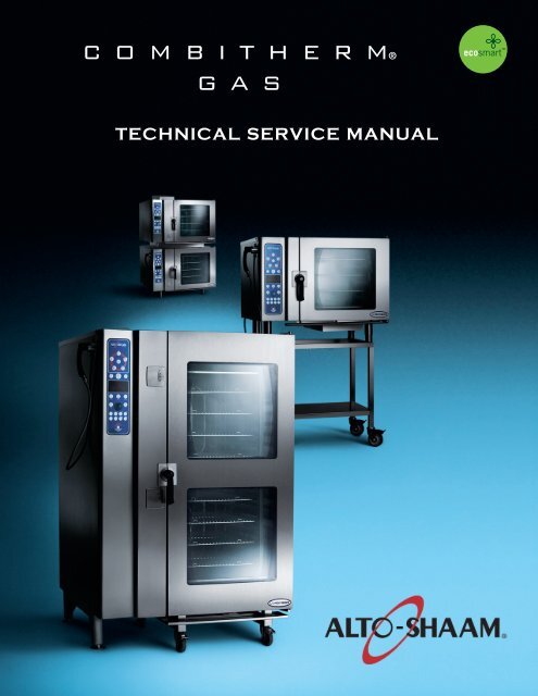
combitherm®<br />
GAS<br />
<strong>Technical</strong> <strong>Service</strong> <strong>Manual</strong>
How to Use this <strong>Technical</strong> <strong>Service</strong> <strong>Manual</strong><br />
This manual has been compiled as a complete resource for a technician working on <strong>Combitherm</strong> <strong>Gas</strong> models. It includes<br />
necessary product information and drawings, along with helpful troubleshooting procedures.<br />
Introduction gives a quick overview of the <strong>Combitherm</strong> <strong>Gas</strong> line to aid in model identification.<br />
Sections 1 through 5 contain information applying to <strong>Combitherm</strong> <strong>Gas</strong> models:<br />
– CONTROL PANEL IDENTIFICATION includes information on using the controllers and operating instructions. It is<br />
the same material supplied to the customer.<br />
– PREVENTIVE MAINTENANCE includes procedures for cleaning. This information is also supplied to the customer.<br />
– SERVICE MODE AND ERROR CODES explains the special programming available to you as a technician to view<br />
status, make adjustments and test functions on models equipped with Standard and Deluxe Controllers. Information is<br />
also included on the use of displayed error codes to resolve problems and on the functions that can be operated under<br />
fault conditions.<br />
– TROUBLESHOOTING TREES are provided for the most common conditions you will be required to address.<br />
– COMBITHERM PARTS has drawings and lists of available parts that apply to the electric models.<br />
Section 6 contains Wiring Diagrams that are specific to each model.<br />
Printing<br />
From this CD, you may print the Current Page or any range of pages. If you would like to print out a complete manual<br />
for a specific model, print pages 1 – 102 (Sections 1 – 5) along with the pages in that model’s section (7.14 ESG, for<br />
example). Here’s a tip: Because printers vary in their capacity to handle large drawings, make a test print of one of the<br />
Wiring Diagrams before printing the model’s section.<br />
COMBITHERM GAS T E C H n I C A l S E R v I C E M A n u A l
COMBITHERM ElECTRIC GAS T E C H nT IEC C AHl nSI CE AR l v ISC E RMv IAC nE uMA l A n• u3A l<br />
TABLE OF CONTENTS<br />
How to Use this <strong>Technical</strong> <strong>Service</strong> <strong>Manual</strong> ..................................... 2<br />
Introduction ................................................................................. 4<br />
1 — Control Panel Identification ................................................. 5<br />
2 — Preventive Maintenance ...................................................... 49<br />
3 — <strong>Service</strong> Mode and Error Codes ............................................ 63<br />
4 — Troubleshooting Trees ........................................................ 68<br />
5 — <strong>Combitherm</strong> <strong>Parts</strong> .............................................................. 78<br />
6 — Wiring Diagrams ................................................................ 115
INTRODUCTION<br />
MODEL NUMBERS<br />
CONTROLLERS<br />
This manual covers the following gas models:<br />
• Standard is a touch key controller.<br />
• Deluxe is a touch key controller with programmable Rapid-Touch keys.<br />
• S-Control is rotary dial controller.<br />
FEATURES AND OPTIONS<br />
MODES<br />
Boiler-Free Models<br />
6.10ESG<br />
10.10ESG<br />
7.14ESG<br />
12.18ESG<br />
10.20ESG<br />
20.20ESG<br />
• Recessed Door is available on all models.<br />
• Smoker Mode is available on boiler-free gas models.<br />
• Core Temp Probe (single point) is optional on S-control models.<br />
The <strong>Combitherm</strong> combination oven/steamer is a multipurpose oven used for:<br />
STEAM MODE<br />
COMBINATION MODE<br />
CONVECTION MODE<br />
RETHERM MODE<br />
CORE TEMPERATURE MODE<br />
COMBITHERM ElECTRIC GAS T E C H nT IEC C AHl nSI CE AR l v ISC E RMv IAC nE uMA l A n• u4A l
CONTROL PANEL IDENTIFICATION<br />
Standard and Deluxe Control ......................................................... 6<br />
S-Control ..................................................................................... 45<br />
Return to Main Table of Contents .................................................. 3<br />
S ECTION 1 – CONTROL P ANEL I DENTIFICATION COMBITHERM GAS TECHNICAL S ERVICE M ANUAL 5<br />
1
CONTROL PANEL IDENTIFICATION<br />
STANDARD AND PROGRAMMABLE DELUXE MODELS<br />
POWER ON/OFF KEY<br />
STEAM MODE KEY<br />
START / STOP KEY<br />
COMBINATION MODE KEY<br />
PROGRAMMED MENU KEY<br />
DELUXE MODELS ONLY DELUXE MODELS ONLY<br />
CHEF FUNCTION KEY<br />
FUNCTION & OPERATING <br />
INDICATORS<br />
COOKING TEMPERATURE KEY<br />
TIME KEY<br />
DOWN ARROW KEY<br />
ADJUSTMENT KNOB<br />
MOISTURE VENT KEY<br />
ELECTRIC MODELS ONLY<br />
RETHERM MODE KEY <br />
CONVECTION MODE KEY <br />
PROGRAM INSTALL/EDIT KEY <br />
CONTROL PANEL DISPLAY <br />
CORE TEMPERATURE KEY <br />
S ECTION 1 – CONTROL P ANEL I DENTIFICATION COMBITHERM GAS TECHNICAL S ERVICE M ANUAL 6<br />
UP ARROW KEY <br />
RAPID-TOUCH KEYS <br />
DELUXE MODELS ONLY
STANDARD & DELUXE CONTROL PANEL BASIC FUNCTION<br />
POWER ON/OFF KEY<br />
Activates power to the oven.<br />
STEAM MODE KEY<br />
The oven will operate in the steam mode at a<br />
temperature range of 86°F to 248°F<br />
(30°C to 120°C).<br />
Automatic steaming at 212°F (100°C)<br />
FACTORY-SET DEFAULT.<br />
Quick steaming between 213°F and 248°F<br />
(101°C and 120°C).<br />
Low Temperature Steaming between<br />
86°F and 211°F (30°C and 99°C).<br />
START/STOP KEY<br />
Initiates all cooking mode functions and<br />
programmed procedures stored in memory.<br />
Stops an activated cooking mode or<br />
programmed procedure currently in progress,<br />
and exits the Chef function key .<br />
COMBINATION MODE KEY<br />
Selection key for cooking with a combination<br />
of steam and convection heat that can be set<br />
within a temperature range of 212°F to 482°F<br />
(100°C to 250°C).<br />
PROGRAMMED MENU KEY<br />
Used to access and exit a menu list of all<br />
stored cooking programs that can be reviewed<br />
in display . DELUXE MODELS ONLY<br />
CHEF FUNCTION KEY<br />
Used to select programmed menu functions,<br />
various auxiliary functions, and several chef<br />
help instructions.<br />
COOKING TEMPERATURE KEY<br />
Used to set the required cooking temperature,<br />
to recall the set cooking temperature, or to<br />
check the actual oven temperature in<br />
conjunction with the down arrow key , the<br />
up arrow key or the adjustment knob .<br />
TIME KEY<br />
Used to set the required cooking time or recall<br />
the set cooking time in conjunction with the<br />
down arrow key , the up arrow key , or<br />
the adjustment knob .<br />
DOWN ARROW KEY<br />
Used to decrease displayed cook temperature<br />
, time , or core temperature and as a<br />
scrolling key for programming functions.<br />
ADJUSTMENT KNOB<br />
Displays oven functions. Serves the same<br />
function as the up and down arrow keys to<br />
increase or decrease the displayed cook<br />
temperature , time , or core temperature .<br />
MOISTURE VENT KEY<br />
Immediately vents steam and condensate from the<br />
oven compartment while cooking in the Convection<br />
mode or in the Combination mode .<br />
RETHERM MODE KEY<br />
Food rethermalization or reheating mode will<br />
operate with automatic steam injection at a<br />
temperature range of 248°F to 320°F<br />
(120°C to 160°C).<br />
CONVECTION MODE KEY<br />
Selection key for convection cooking without<br />
steam at a temperature range of 86°F to 482°F<br />
(30°C to 250°C).<br />
PROGRAM INSTALL AND EDIT KEY<br />
Used to create, change, duplicate, and delete<br />
programmed menus. DELUXE MODELS ONLY.<br />
CONTROL PANEL DISPLAY<br />
CORE TEMPERATURE KEY<br />
Used to set the required internal product<br />
temperature, to recall the internal product<br />
temperature set by the operator, or to display<br />
the current internal temperature of the product<br />
in conjunction with the down arrow key , the<br />
up arrow key , or the adjustment knob .<br />
UP ARROW KEY<br />
Used to increase displayed cook temperature<br />
, time , or core temperature and as a<br />
scrolling key for programming functions.<br />
RAPID-TOUCH KEYS DELUXE MODELS ONLY.<br />
One-touch cooking for immediate access to<br />
frequently used operator set programs including<br />
cooking modes, cleaning, and other oven functions.<br />
S ECTION 1 – CONTROL P ANEL I DENTIFICATION COMBITHERM GAS TECHNICAL S ERVICE M ANUAL 7<br />
CONTINUED
STANDARD & DELUXE CONTROL PANEL BASIC FUNCTIONS<br />
FUNCTION & OPERATING INDICATORS<br />
A. GOLD-N-BROWN FEATURE<br />
This indicator will illuminate when the browning function is set by the operator in a<br />
timed or programmed cooking cycle in either convection mode or combination mode.<br />
B. COMBI SMOKER (ON EQUIPPED MODELS)<br />
This indicator will illuminate when the smoking function is set by the operator in a<br />
timer, probe or programmed cooking cycle in either convection mode or combination<br />
mode.<br />
C. REDUCED FAN SPEED<br />
This indicator will illuminate whenever the operator sets a reduced fan speed to<br />
protect products affected by high-velocity air movement.<br />
D. CONFIRMATION OF OVEN OPERATION<br />
This indicator illuminates whenever the oven is operating in any mode.<br />
E. KEY LOCK<br />
This indicator will illuminate when operator has locked any mode key or function to<br />
prevent unauthorized or accidental changes.<br />
F. MOISTURE VENT<br />
This indicator will illuminate whenever the Moisture Vent Key <br />
is pressed by the operator to eliminate excessive moisture.<br />
G. ENERGY LOCK<br />
FOR USE WITH OVENS INSTALLED UNDER AN ALTO-SHAAM VENTLESS HOOD.<br />
This indicator is a safety feature that will illuminate and prevent the oven from being<br />
operated unless the ventless oven hood is operating.<br />
S ECTION 1 – CONTROL P ANEL I DENTIFICATION COMBITHERM GAS TECHNICAL S ERVICE M ANUAL 8
SET UP MENU<br />
SET-UP PROCEDURES<br />
Following installation, the control should be set with the date and time. In addition to the date and time,<br />
the set-up function provides the operator with the ability to adjust a number of other <strong>Combitherm</strong><br />
operating conditions to conform with the needs of the individual installation.<br />
PRESS THE ON/OFF POWER KEY<br />
TO THE ON POSITION.<br />
PRESS THE CHEF FUNCTION KEY.<br />
Rotate the adjustment knob<br />
until the set up symbol is<br />
highlighted within the display.<br />
PRESS THE CHEF FUNCTION KEY.<br />
Press the up ▲ and down ▼ arrow keys<br />
or rotate the adjustment knob to select<br />
“YES” for the set up function.<br />
PRESS THE CHEF FUNCTION KEY TO<br />
CONFIRM THE SET UP FUNCTION.<br />
Press the up ▲ and down ▼ arrow keys<br />
or rotate the adjustment knob to<br />
highlight one of the following<br />
adjustment functions:<br />
SIGNAL TONE<br />
Set up<br />
SET UP ADJUSTMENT CHOICES<br />
SIGNAL TONE<br />
VOLUME<br />
TIME<br />
DATE<br />
PROGRAM INDEX<br />
DEFAULT/MEMO SETTINGS<br />
TEMPERATURE DISPLAY<br />
NETWORK ADDRESS<br />
LANGUAGE<br />
Rotate the adjustment knob until the signal tone symbol is highlighted within the display.<br />
PRESS THE CHEF FUNCTION KEY TO CONFIRM THE SIGNAL TONE SELECTION.<br />
Press the up ▲ and down ▼ arrow keys or rotate the adjustment knob to select each tone offered.<br />
Stop rotation at each individual setting to hear an audio playback. Select the tone desired.<br />
PRESS THE CHEF FUNCTION KEY TO CONFIRM THE SELECTED SIGNAL TONE SETTING.<br />
S ECTION 1 – CONTROL P ANEL I DENTIFICATION COMBITHERM GAS TECHNICAL S ERVICE M ANUAL 9
ALWAYS BEGIN SET UP ADJUSTMENTS FROM THE SET UP MENU .<br />
VOLUME<br />
TIME<br />
DATE<br />
Rotate the adjustment knob until the volume symbol is highlighted within the display.<br />
PRESS THE CHEF FUNCTION KEY TO CONFIRM THE VOLUME SELECTION.<br />
Press the up ▲ and down ▼ arrow keys or rotate the adjustment knob to select each volume level<br />
offered. Stop rotation at each individual setting to hear an audio playback. Select the volume<br />
desired with consideration of the noise level within the kitchen during peak production periods.<br />
PRESS THE CHEF FUNCTION KEY TO CONFIRM THE VOLUME SETTING.<br />
Rotate the adjustment knob until the time symbol is highlighted within the display.<br />
PRESS THE CHEF FUNCTION KEY TO CONFIRM THE TIME SELECTION.<br />
Press the up ▲ and down ▼ arrow keys to alternate between hours and minutes and rotate the<br />
adjustment knob in each to adjust the numbers to the correct time.<br />
PRESS THE CHEF FUNCTION KEY TO CONFIRM THE SET TIME.<br />
Rotate the adjustment knob until the date symbol is highlighted within the display.<br />
PRESS THE CHEF FUNCTION KEY TO CONFIRM THE DATE SELECTION.<br />
Rotate the adjustment knob to select the preferred date format.<br />
Press the up ▲ and down ▼ arrow keys to alternate between day, month and year, and rotate the<br />
adjustment knob in each to adjust the numbers to the correct settings.<br />
PRESS THE CHEF FUNCTION KEY TO CONFIRM THE SET DATE.<br />
PROGRAM INDEX<br />
SET-UP PROCEDURES<br />
Rotate the adjustment knob until the program index symbol is highlighted within the display.<br />
PRESS THE CHEF FUNCTION KEY TO CONFIRM THE PROGRAM INDEX SELECTION.<br />
Press the up ▲ and down ▼ arrow keys or rotate the adjustment knob to select the preferred index format:<br />
“YES” for a listing of programs entered alphabetically with the program install/edit key.<br />
“NO” for a listing of programs entered numerically with the program install/edit key.<br />
PRESS THE CHEF FUNCTION KEY TO CONFIRM THE PROGRAM INDEX SETTING.<br />
S ECTION 1 – CONTROL P ANEL I DENTIFICATION COMBITHERM GAS TECHNICAL S ERVICE M ANUAL 10
SET-UP PROCEDURES<br />
ALWAYS BEGIN SET UP ADJUSTMENTS FROM THE SET UP MENU .<br />
DEFAULT/MEMO SETTING<br />
The default/memo setting allows the operator to choose<br />
between a display showing the factory set defaults for<br />
time and temperature or the last operator set values for<br />
time and temperature in each cooking mode. This<br />
adjustment function also allows the operator to change<br />
the defaults from those set at the factory to settings that<br />
better meet the needs of the individual operation.<br />
Rotate the adjustment knob until the default/memo symbol is highlighted within the display.<br />
PRESS THE CHEF FUNCTION KEY TO CONFIRM THE DEFAULT/MEMO SELECTION.<br />
Rotate the adjustment knob to “NO” for memo. This setting will display the last operator set values for<br />
time and temperature in each cooking mode.<br />
PRESS THE CHEF FUNCTION KEY TO CONFIRM THE MEMO SETTING.<br />
TO CHANGE THE DEFAULT SETTINGS<br />
Rotate the adjustment knob to select “YES”.<br />
A numbered list of default descriptions will appear in the display. Rotate the adjustment knob<br />
until the setting to be changed is highlighted. Press the up ▲ arrow key to highlight the time or<br />
temperature to be changed. Rotate the adjustment knob to change the default to the setting<br />
desired. Press the down ▼ arrow key to save the new default setting.<br />
PRESS THE CHEF FUNCTION KEY TO CONFIRM THE NEW DEFAULT SETTINGS.<br />
COOKING<br />
MODE<br />
COMBITHERM FACTORY SET DEFAULT SETTINGS<br />
OVEN<br />
TEMPERATURE<br />
Cooking product with operator set defaults for time and<br />
temperature can help reduce operator error. Cooking<br />
with the oven in the memo setting is particularly useful<br />
when several batches are cooked in succession. The<br />
memo setting eliminates the necessity to set time and<br />
temperature for each batch.<br />
CORE<br />
TEMPERATURE<br />
COOKING<br />
TIME<br />
STEAM 212°F 158°F 25 MINUTES<br />
MODE (100°C) (70°C)<br />
COMBINATION 302°F 158°F 70 MINUTES<br />
STEAM MODE (150°C) (70°C)<br />
CONVECTION 338°F 158°F 30 MINUTES<br />
MODE (170°C) (70°C)<br />
RETHERM 275°F 158°F 5 MINUTES<br />
MODE (135°C) (70°C)<br />
DELTA-T 122°F 172°F FREE<br />
MODE (50°C) (77°C)<br />
PREHEAT 374°F FREE —<br />
MODE (140°C)<br />
S ECTION 1 – CONTROL P ANEL I DENTIFICATION COMBITHERM GAS TECHNICAL S ERVICE M ANUAL 11
ALWAYS BEGIN SET UP ADJUSTMENTS FROM THE SET UP MENU .<br />
TEMPERATURE DISPLAY<br />
Rotate the adjustment knob until the temperature display symbol is highlighted within the display.<br />
PRESS THE CHEF FUNCTION KEY TO CONFIRM THE TEMPERATURE DISPLAY SELECTION.<br />
Press the up ▲ and down ▼ arrow keys or rotate the<br />
adjustment knob to select either Fahrenheit or Celsius.<br />
PRESS THE CHEF FUNCTION KEY TO CONFIRM THE TEMPERATURE DISPLAY SETTING.<br />
NETWORK ADDRESS<br />
Press the up ▲ and down ▼ arrow keys or rotate the adjustment knob until the network address<br />
symbol is highlighted within the display.<br />
PRESS THE CHEF FUNCTION KEY TO CONFIRM THE NETWORK ADDRESS SELECTION.<br />
The current network address will appear in the display.<br />
Rotate the adjustment knob to select 1 through 99 and assign<br />
a different network number for each PC to be connected.<br />
PRESS THE CHEF FUNCTION KEY TO CONFIRM EACH NETWORK ADDRESS.<br />
LANGUAGE<br />
Press the up ▲ and down ▼ arrow keys or rotate the adjustment knob<br />
until the language symbol is highlighted within the display.<br />
PRESS THE CHEF FUNCTION KEY TO CONFIRM THE LANGUAGE PROGRAM SELECTION.<br />
Rotate the adjustment knob to select the required language.<br />
CHINESE<br />
DUTCH<br />
ENGLISH*<br />
FRENCH<br />
GERMAN<br />
SET-UP PROCEDURES<br />
ITALIAN<br />
JAPANESE<br />
KOREAN<br />
POLISH<br />
PORTUGUESE<br />
*U.S. FACTORY SETTING<br />
NOTE: SOME OF THE LANGUAGE SELECTIONS SHOWN ABOVE MAY NOT BE AVAILABLE ON ALL MODELS.<br />
PRESS THE CHEF FUNCTION KEY TO CONFIRM THE LANGUAGE SETTING.<br />
RUSSIAN<br />
SPANISH<br />
SWEDISH<br />
S ECTION 1 – CONTROL P ANEL I DENTIFICATION COMBITHERM GAS TECHNICAL S ERVICE M ANUAL 12
IMPORTANT SAFETY PRECAUTIONS<br />
NOTE: Automatic steam venting is a standard<br />
safety feature built into all <strong>Combitherm</strong><br />
oven models. This feature vents all<br />
steam from the oven compartment<br />
IMMEDIATELY BEFORE COOKING<br />
TIME EXPIRES.<br />
This function is provided in all<br />
programmed and timed production<br />
when operating in any Steam,<br />
Combination, Convection, and Retherm<br />
cooking mode. Automatic steam<br />
venting does not function if the oven<br />
door is opened before time expires or<br />
when the oven has been set to<br />
continuous operation.<br />
AT NO TIME SHOULD THE INTERIOR OR<br />
EXTERIOR BE STEAM CLEANED, HOSED<br />
DOWN, OR FLOODED WITH WATER OR<br />
LIQUID SOLUTION OF ANY KIND. DO NOT<br />
USE WATER JET TO CLEAN.<br />
SEVERE DAMAGE OR<br />
ELECTRICAL HAZARD COULD RESULT.<br />
WARRANTY BECOMES VOID IF APPLIANCE IS FLOODED.<br />
DO NOT HANDLE PANS CONTAINING LIQUID<br />
OR SEMILIQUID PRODUCTS POSITIONED<br />
ABOVE THE EYE LEVEL OF THE OPERATOR.<br />
SUCH PRODUCTS CAN SCALD AND CAUSE<br />
SERIOUS INJURY.<br />
DO NOT USE THE ATTACHED HAND-<br />
HELD HOSE TO SPRAY ANYTHING OTHER<br />
THAN THE INTERIOR OF THE COMBITHERM<br />
OVEN COMPARTMENT.<br />
DO NOT USE THE SPRAY HOSE<br />
ON THE SURFACE OF A HOT COOKING<br />
COMPARTMENT. ALLOW THE OVEN TO<br />
COOL TO A MINIMUM OF 150°F (66°C).<br />
NOTE: USE AUTHORIZED COMBITHERM OVEN CLEANER ONLY.<br />
UNAUTHORIZED CLEANING AGENTS MAY DISCOLOR OR HARM INTERIOR SURFACES OF THE<br />
OVEN. READ AND UNDERSTAND LABEL AND MATERIAL SAFETY DATA SHEET BEFORE USING<br />
THE OVEN CLEANER.<br />
FOR OPERATOR SAFETY<br />
HOT STEAM CAUSES BURNS<br />
ROTATE THE DOOR HANDLE TO THE<br />
FIRST OPEN ROTATION POSITION ONLY.<br />
WAIT UNTIL THE STEAM IS VENTED BEFORE<br />
FULLY OPENING THE DOOR.<br />
METAL PARTS OF THIS EQUIPMENT<br />
BECOME EXTREMELY HOT WHEN IN<br />
OPERATION. TO AVOID BURNS,<br />
ALWAYS USE HAND PROTECTION<br />
WHEN OPERATING THIS APPLIANCE.<br />
NOTE AND OBSERVE ALL SAFETY PRECAUTIONS LOCATED THROUGHOUT THIS GUIDE.<br />
S ECTION 1 – CONTROL P ANEL I DENTIFICATION COMBITHERM GAS TECHNICAL S ERVICE M ANUAL 13
STEAM MODE<br />
STEAM ● LOW TEMPERATURE STEAM ● QUICK STEAM<br />
The Steam mode provides the operator with the ability to steam, poach, or blanch.<br />
This mode will automatically steam at the boiling point of water; quick-steam above the<br />
boiling point for faster cooking results; or low temperature steam, below the boiling point,<br />
for more delicate products such as pâté, mousse, seafood, or custard.<br />
PRESS THE ON/OFF POWER KEY TO THE ON POSITION.<br />
PRESS THE STEAM MODE KEY.<br />
Automatic Steam temperature of 212°F (100°C) will appear in the display.<br />
The last set time or oven control default setting for time will appear in the display.<br />
TO CHANGE THE SETTINGS SHOWN:<br />
PRESS THE START KEY TO STEAM AT THE SETTINGS SHOWN.<br />
PRESS THE TEMPERATURE KEY.<br />
The cooking temperature will appear highlighted within the oven display.<br />
TO COOK BY TIME:<br />
Press the up ▲ and down ▼ arrow keys or rotate the adjustment knob to select<br />
the desired cooking temperature.<br />
Automatic Steaming 212°F (100°C)<br />
Quick-steaming 213°F to 248°F (101°C to 120°C)<br />
Low Temperature Steaming 86°F to 211°F (30°C to 99°C)<br />
PRESS THE TIME KEY.<br />
The cooking time will appear highlighted within the oven display.<br />
Press the up ▲ and down ▼ arrow keys or rotate the adjustment knob to<br />
select the time desired…<br />
or<br />
Set control for continuous operation by rotating the adjustment knob to the right until<br />
appears in the display.<br />
TO COOK BY INTERNAL PRODUCT TEMPERATURE:<br />
PRESS THE CORE TEMP KEY.<br />
The previously set core temperature or oven control default setting will appear<br />
highlighted within the oven display.<br />
Press the up ▲ and down ▼ arrow keys or rotate the adjustment knob to<br />
select the internal temperature desired and insert the product probe.<br />
PRESS THE START KEY TO BEGIN COOKING IN THE STEAM MODE.<br />
The set cooking temperature will appear in the display. To adjust the set temperature, press the key<br />
once and make corrections as required. To display the actual oven temperature, press the key twice.<br />
The remaining cooking time will appear in the display. To display the set time or to change the set<br />
values for time during operation, press the time key once and make corrections as required.<br />
The actual internal product temperature will appear in the display. To display the set internal product<br />
temperature or to change the set values for core temperature during operation, press the key once<br />
and make corrections as required.<br />
When the cooking time has expired or the operator set internal temperature has been reached, a buzzer<br />
will sound indicating the end of the operating mode.<br />
To stop the buzzer, press the start/stop key or open the oven door.<br />
S ECTION 1 – CONTROL P ANEL I DENTIFICATION COMBITHERM GAS TECHNICAL S ERVICE M ANUAL 14
STEAM<br />
Perforated, 2-1/2" deep pans<br />
(65mm) are particularly suitable<br />
for use in this program mode.<br />
These pans will provide a shorter<br />
cooking time and will prevent<br />
product over-cooking at the<br />
bottom of the pan.<br />
Separate ice-encased vegetables<br />
before steaming to assure more<br />
even cooking.<br />
A variety of products can be<br />
steamed at the same time but<br />
attention must be paid to the<br />
different cooking times required<br />
for each food product.<br />
Butter and season vegetables<br />
after steaming.<br />
Steam long-grain rice using<br />
approximately 1-part rice to<br />
approximately 1-1/2-parts water<br />
or seasoned liquid.<br />
Steam durum wheat noodles in<br />
unperforated pans using 1-part<br />
noodles to 5-parts cold water.<br />
STEAM MODE<br />
CHEF OPERATING TIPS<br />
This mode will steam a full or partial load of a single product, or multiple products<br />
without transfer of flavors. When steaming multiple products, however, individual<br />
product cooking times must be taken into consideration. The non-pressurized<br />
atmosphere of the <strong>Combitherm</strong> also provides the ability to open the door during the<br />
steam mode in order to monitor products more closely throughout the steaming process.<br />
QUICK STEAMING<br />
Quick steaming is suitable<br />
for hearty, root-type vegetables<br />
such as potatoes, legumes,<br />
and cabbage.<br />
Quick steaming provides a<br />
cooking time which is<br />
approximately 10-percent shorter<br />
than the regular steam mode<br />
temperature of 212°F (100°C).<br />
Set the steam cooking<br />
temperature between 221°F<br />
(105°C) and 230°F (110°C) for<br />
small loads and between 230°F<br />
(110°C) and 248°F (120°C) for<br />
full loads.<br />
LOW TEMP STEAM<br />
The low temperature steam mode<br />
will function whenever the oven<br />
compartment temperature is<br />
below 212°F (100°C).<br />
Proof yeast dough at a<br />
temperature setting of 90°F to<br />
110°F (32°C to 43°C).<br />
It will take longer to steam<br />
products using the low<br />
temperature steam mode.<br />
Steaming sausages in low<br />
temperature steam prevents<br />
cracked or peeling skins.<br />
Use low temperature steam for<br />
delicate foods such as shrimp,<br />
fish, seafood, and crème caramel.<br />
For best results, low temperature<br />
steam all delicate food items at a<br />
temperature of 210°F (99°C)<br />
or below.<br />
S ECTION 1 – CONTROL P ANEL I DENTIFICATION COMBITHERM GAS TECHNICAL S ERVICE M ANUAL 15
The Combination mode will prove to be the most versatile and widely used mode<br />
the <strong>Combitherm</strong> oven has to offer. It will produce the best possible results on the<br />
widest variety of products — all within the shortest period of time. The unique control<br />
function of this mode enables the operator to roast or bake with a combination of<br />
steam and convection heat. In addition to shorter cooking times, this combination of<br />
steam and heat offers less product shrinkage and more moisture retention than obtained<br />
in a standard convection oven.<br />
PRESS THE ON/OFF POWER KEY TO THE ON POSITION.<br />
PRESS THE COMBINATION MODE KEY.<br />
The last set values or oven control default setting for temperature will appear in the display.<br />
The last set time or oven control default setting for time will appear in the display.<br />
TO CHANGE THE SETTINGS SHOWN:<br />
PRESS THE START KEY TO COOK AT THE SETTINGS SHOWN.<br />
PRESS THE TEMPERATURE KEY.<br />
The cooking temperature will appear highlighted within the oven display.<br />
TO COOK BY TIME:<br />
COMBINATION MODE<br />
Press the up ▲ and down ▼ arrow keys or rotate the adjustment knob to<br />
select the desired cooking temperature.<br />
212°F to 482°F (100°C to 250°C)<br />
PRESS THE TIME KEY.<br />
The cooking time will appear highlighted within the oven display.<br />
Press the up ▲ and down ▼ arrow keys or rotate the adjustment knob to select<br />
the time desired…<br />
or<br />
Set control for continuous operation by rotating the adjustment knob to the right until<br />
appears in the display.<br />
TO COOK BY INTERNAL PRODUCT TEMPERATURE:<br />
PRESS THE CORE TEMP KEY.<br />
The core temperature will appear highlighted within the oven display.<br />
Press the up ▲ and down ▼ arrow keys or rotate the adjustment knob to<br />
select the internal temperature desired and insert the product probe.<br />
PRESS THE START KEY TO BEGIN COOKING IN THE COMBINATION MODE.<br />
The set cooking temperature will appear in the display. To adjust the set temperature, press the key<br />
once and make corrections as required. To display the actual oven temperature, press the key twice.<br />
The remaining cooking time will appear in the display. To display the set time or to change the set<br />
values for time during operation, press the time key once and make corrections as required.<br />
The actual internal product temperature will appear in the display. To display the set internal<br />
product temperature or to change the set values for core temperature during operation, press the<br />
key once and make corrections as required.<br />
When the cooking time has expired or the operator set internal temperature has been reached, a<br />
buzzer will sound indicating the end of the operating mode.<br />
To stop the buzzer, press the start/stop key or open the oven door.<br />
S ECTION 1 – CONTROL P ANEL I DENTIFICATION COMBITHERM GAS TECHNICAL S ERVICE M ANUAL 16
Due to the automatic steam adjustment, the<br />
door can be opened at any time during a<br />
cooking operation. Be certain to observe the<br />
safety warning when opening the oven door.<br />
The Combination mode is particularly efficient<br />
when used for baking, broiling, grilling, stewing,<br />
braising, and roasting.<br />
When using the Combination mode, cooking<br />
temperatures can be reduced 10- to 20-percent<br />
below the temperatures used for conventional<br />
cooking methods.<br />
Cooking time will be reduced approximately<br />
40-percent when cooking at the same temperature<br />
used for convection oven cooking and up to 50- to<br />
60-percent less time when cooking at the same<br />
temperature used for a conventional oven.<br />
COMBINATION MODE<br />
CHEF OPERATING TIPS<br />
The Combination mode injects the optimum amount of steam<br />
automatically. There is no need to select moisture levels. Foods do not<br />
dry out. Flavors are retained with no transfer of flavors when mixing<br />
product loads.<br />
Food browning in the <strong>Combitherm</strong> begins<br />
at a cooking temperature of approximately<br />
248°F (120°C).<br />
A higher cooking temperature results in heavier<br />
browning but also results in greater product<br />
weight loss. To achieve additional browning use<br />
the Moisture Vent Key or set Gold-n-Brown into<br />
the product procedure. Gold-n-Brown is<br />
particularly useful for adding color to high moisture<br />
products such as chicken and other poultry items<br />
or for additional browning of full loads and other<br />
moist products.<br />
The Combination mode provides even browning<br />
without the necessity to turn the pans.<br />
For more even cooking, do not cook in pans<br />
deeper than 4-inches (100mm).<br />
S ECTION 1 – CONTROL P ANEL I DENTIFICATION COMBITHERM GAS TECHNICAL S ERVICE M ANUAL 17
The Convection mode operates with hot circulated air within a temperature range<br />
of 86° to 482°F (30° to 250°C). For many applications, better results may be<br />
achieved with the Combination mode; therefore, the operator may want to consider<br />
using the Convection mode on a more limited basis.<br />
PRESS THE ON/OFF POWER KEY TO THE ON POSITION.<br />
PRESS THE CONVECTION MODE KEY.<br />
The last set values or oven control default setting for temperature will appear in the display.<br />
The last set time or oven control default setting for time will appear in the display.<br />
TO CHANGE THE SETTINGS SHOWN:<br />
PRESS THE START KEY TO COOK AT THE SETTINGS SHOWN.<br />
PRESS THE TEMPERATURE KEY.<br />
The cooking temperature will appear highlighted within the oven display.<br />
TO COOK BY TIME:<br />
CONVECTION MODE<br />
Press the up ▲ and down ▼ arrow keys or rotate the adjustment knob<br />
to select the desired cooking temperature.<br />
86° to 482°F (30° to 250°C)<br />
PRESS THE TIME KEY.<br />
The cooking time will appear highlighted within the oven display.<br />
Press the up ▲ and down ▼ arrow keys or rotate the adjustment knob to select the<br />
time desired…<br />
or<br />
Set control for continuous operation by rotating the adjustment knob to the right until<br />
appears in the display.<br />
TO COOK BY INTERNAL PRODUCT TEMPERATURE:<br />
PRESS THE CORE TEMP KEY.<br />
The core temperature will appear highlighted within the oven display.<br />
Press the up ▲ and down ▼ arrow keys or rotate the adjustment knob to<br />
select the internal temperature desired and insert the product probe.<br />
PRESS THE START KEY TO BEGIN THE COOKING MODE.<br />
The set cooking temperature will appear in the display. To adjust the set temperature, press the key<br />
once and make corrections as required. To display the actual oven temperature, press the key twice.<br />
The remaining cooking time will appear in the display. To display the set time or to change the set<br />
values for time during operation, press the time key once and make corrections as required.<br />
The actual internal product temperature will appear in the display. To display the set internal product<br />
temperature or to change the set values for core temperature during operation, press the key once<br />
and make corrections as required.<br />
When the cooking time has expired or the operator set internal temperature has been reached, a buzzer<br />
will sound indicating the end of the operating mode.<br />
To stop the buzzer, press the start/stop key or open the oven door.<br />
To check the length of time the product has been operating in the core temperature mode, press and hold the<br />
time key along with the core temperature key . The time period will appear at the top of the display.<br />
S ECTION 1 – CONTROL P ANEL I DENTIFICATION COMBITHERM GAS TECHNICAL S ERVICE M ANUAL 18
The Convection mode works best with foods<br />
containing little moisture or for very moist food<br />
which require a dryer finished product.<br />
For baking, preheat the <strong>Combitherm</strong> at a<br />
temperature of 36°F to 54°F (20°C to 30°C) above<br />
the baking temperature required. Once preheated,<br />
reset the temperature as required.<br />
CONVECTION MODE<br />
CHEF OPERATING TIPS<br />
The Convection Mode can be used to roast or bake products needing very<br />
short cooking times or for high moisture products such as muffins, cakes,<br />
and cookies, or for browning the surface of the product.<br />
A higher cooking temperature results in heavier<br />
browning but also results in greater product weight<br />
loss. To achieve additional browning use the<br />
Moisture Vent Key or set the Browning Feature<br />
into the product procedure.<br />
To prevent the surface of food from excessive<br />
drying, the fan will not engage if the internal<br />
oven temperature is above 212°F (100°C)<br />
and the set oven temperature is below<br />
212°F (100°C).<br />
S ECTION 1 – CONTROL P ANEL I DENTIFICATION COMBITHERM GAS TECHNICAL S ERVICE M ANUAL 19
The Retherm mode can be used to rethermalize (regenerate) portioned food on<br />
plates, trays, or platters within a short period of time. Steam is automatically injected<br />
into the oven compartment as required. Items are brought up to proper serving<br />
temperatures without dry edges or condensate forming on the plates.<br />
PRESS THE ON/OFF POWER KEY TO THE ON POSITION.<br />
PRESS THE RETHERM MODE KEY.<br />
The last set values or the default settings will appear in the display.<br />
TO CHANGE THE SETTINGS SHOWN:<br />
PRESS THE START KEY TO COOK AT THE SETTINGS SHOWN.<br />
PRESS THE TEMPERATURE KEY.<br />
The cooking temperature will appear highlighted within the oven display.<br />
TO COOK BY TIME:<br />
RETHERM MODE<br />
Press the up ▲ and down ▼ arrow keys or rotate the adjustment knob<br />
to select the desired cooking temperature.<br />
248° to 320°F (120° to 180°C)<br />
PRESS THE TIME KEY.<br />
The cooking time will appear highlighted within the oven display.<br />
Press the up ▲ and down ▼ arrow keys or rotate the adjustment knob to select the<br />
time desired…<br />
or<br />
Set control for continuous operation by rotating the adjustment knob to the<br />
right until appears in the display.<br />
TO COOK BY INTERNAL PRODUCT TEMPERATURE:<br />
PRESS THE CORE TEMP KEY.<br />
The core temperature will appear highlighted within the oven display.<br />
Press the up ▲ and down ▼ arrow keys or rotate the adjustment knob to<br />
select the internal temperature desired and insert the product probe.<br />
PRESS THE START KEY TO BEGIN THE RETHERM MODE.<br />
The set cooking temperature will appear in the display. To adjust the set temperature, press the key<br />
once and make corrections as required. To display the actual oven temperature, press the key twice.<br />
The remaining cooking time will appear in the display. To display the set time or to change the set<br />
values for time during operation, press the time key once and make corrections as required.<br />
The actual internal product temperature will appear in the display. To display the set internal product<br />
temperature or to change the set values for core temperature during operation, press the key once<br />
and make corrections as required.<br />
When the cooking time has expired or the operator set internal temperature has been reached, a buzzer<br />
will sound indicating the end of the operating mode.<br />
To stop the buzzer, press the start/stop key or open the oven door.<br />
To check the length of time the product has been operating in the core temperature mode, press and hold the<br />
time key along with the core temperature key . The time period will appear at the top of the display.<br />
S ECTION 1 – CONTROL P ANEL I DENTIFICATION COMBITHERM GAS TECHNICAL S ERVICE M ANUAL 20
RETHERM MODE CHEF OPERATING TIPS<br />
Since plated meals consist of dissimilar products, there are several important factors<br />
to consider in order to produce the finest results. Product density (compactness),<br />
thickness, quantity of product on each plate, and quantity of plates all relate to the<br />
length of time necessary to reheat. Again, experience is the best method to<br />
determine reheating time. Once the time has been determined and recorded for a<br />
specific meal, the results will be consistent for future reheating times.<br />
HELPFUL HINTS FOR REHEATING ON THE PLATE<br />
ALL FOOD COMPONENTS ON THE PLATE SHOULD BE OF SIMILAR DENSITIES.<br />
ALL FOOD COMPONENTS ON THE PLATE SHOULD BE SIMILAR IN THICKNESS.<br />
ARRANGE ALL FOOD COMPONENTS EVENLY ON THE PLATE.<br />
AVOID EXCESSIVE OVERLAPPING OF PRODUCT.<br />
SAUCES MUST BE HEATED AND ADDED TO PRODUCT AFTER REHEATING.<br />
A MIXED VARIETY OF MEALS CAN BE REHEATED AT THE SAME TIME.<br />
À LA CARTE RETHERMALIZATION<br />
À la carte rethermalization is designed to take<br />
a single plate from a refrigerated temperature to<br />
serving temperature for immediate service. Plates<br />
are prepared in advance, covered, and refrigerated.<br />
Preheat the <strong>Combitherm</strong> oven. Remove plate from<br />
refrigeration and place in the oven at 275°F (135°C)<br />
for an uncovered plate or 300°F (150°C) for a<br />
covered plate. Plates with meat components will<br />
take more time than plates containing all vegetable<br />
components. Follow internal temperature<br />
requirements for reheating and allow for override<br />
time. After reheating, remove the plate from the<br />
oven, add any sauces, garnish, and serve. This<br />
process can be repeated as required.<br />
For the most efficient continuous service, it is<br />
suggested that the <strong>Combitherm</strong> oven be dedicated to<br />
the rethermalization process during serving hours.<br />
BANQUET RETHERMALIZATION<br />
Banquet rethermalization is designed for high<br />
volume, full or partial load (multiple plate) reheating.<br />
For maximum efficiency, it is essential that volume<br />
rethermalization be used in conjunction with the<br />
utilization of holding cabinets to keep rethermalized<br />
food at proper temperatures.<br />
Plates are assembled in advance, covered, and<br />
refrigerated or loaded on the roll-in cart and<br />
refrigerated. Preheat the <strong>Combitherm</strong> oven at<br />
275°F (135°C) for uncovered plates or 300°F (150°C)<br />
for covered plates. Remove plates or the roll-in cart<br />
from refrigeration, load in the oven and set timer as<br />
required. Follow internal temperature requirements<br />
for reheating and allow for override time. Remove<br />
the plates or roll-in cart from the <strong>Combitherm</strong> and<br />
roll into the companion holding cabinet. Relocate<br />
the holding cabinet to the banquet service area.<br />
RETHERMALIZING PREFABRICATED AND<br />
VACUUM-PACKED FROZEN FOODS<br />
For bulk product rethermalization, completely<br />
defrost product bags in walk-in cooler. DO NOT<br />
REMOVE PRODUCT FROM THE BAG. Load<br />
thawed bags in preheated oven and rethermalize in<br />
the Low Temperature Steam mode until the required<br />
internal temperature is reached. Place rethermalized<br />
bags in a preheated holding cabinet set at<br />
140° to 165°F (60° to 74°C) until ready for service.<br />
For large volume on-the-plate regeneration,<br />
defrost bags in walk-in cooler. Open bags and plate<br />
per menu requirements in a (MAXIMUM) 55°F (13°C)<br />
refrigerated room. Cover plates, place on Alto-Shaam<br />
roll-in cart (trolley), and roll into <strong>Combitherm</strong> oven<br />
preheated at 275°F (135°C).<br />
Regenerate in the Convection mode for 3 to 5<br />
minutes. Switch to the Retherm mode for an<br />
additional 3 minutes or more if required. Transfer<br />
full trolley to a preheated holding cabinet set at<br />
160°F (71°C) until ready for service. In the case of<br />
meat cooked to rare, set the cabinet at 140°F (60°C).<br />
PLATE COVERS MUST BE USED FOR ON-THE-PLATE REGENERATION.<br />
S ECTION 1 – CONTROL P ANEL I DENTIFICATION COMBITHERM GAS TECHNICAL S ERVICE M ANUAL 21
CORE TEMPERATURE PROBE MODE<br />
As an alternative to timer operation, the Core Temperature Probe mode can<br />
be used in conjunction with any program mode to cook by sensing internal<br />
product temperature. For a more accurate internal temperature, a<br />
specialized <strong>Combitherm</strong> product probe senses temperature from four strategic<br />
points and displays a temperature average.<br />
PRESS THE ON/OFF POWER KEY TO THE ON POSITION.<br />
INSERT THE PRODUCT PROBE.<br />
The probe must be inserted so that the tip is positioned in the center of the food mass.<br />
For liquid or semiliquid foods, suspend the probe in the center of the product and<br />
secure the probe wire to the container edge.<br />
SELECT AND PRESS THE REQUIRED COOKING PROGRAM.<br />
PRESS THE TEMPERATURE KEY.<br />
The cooking temperature will appear highlighted within the oven display.<br />
Press the up ▲ and down ▼ arrow keys or rotate the adjustment knob to<br />
select the desired cooking temperature within the temperature range of<br />
the cooking mode selected.<br />
PRESS THE CORE TEMP KEY.<br />
The core temperature will appear highlighted within the oven display.<br />
Press the up ▲ and down ▼ arrow keys or rotate the adjustment knob to<br />
select the internal product cutoff temperature.<br />
PRESS THE START KEY TO BEGIN THE COOKING MODE.<br />
The actual internal product temperature will appear in the display. To display the set internal product<br />
temperature or to change the set values for core temperature during operation, press the key once<br />
and make corrections as required.<br />
When the operator set internal temperature has been reached, a buzzer will sound indicating the end of<br />
the operating mode.<br />
To stop the buzzer, press the start/stop key or open the oven door.<br />
To check the length of time the product has been operating in the core temperature mode, press and hold the<br />
time key along with the core temperature key . The time period will appear at the top of the display.<br />
CHEF OPERATING TIPS<br />
To prevent over-cooking, remove product from the oven as soon as the required internal<br />
temperature is reached in either the Core Temperature mode or the Core Temperature Delta-T<br />
mode. The Core Temperature mode should not be used for cooking thin product items.<br />
DO NOT USE THE PROBE WHEN COOKING THIN PRODUCTS.<br />
S ECTION 1 – CONTROL P ANEL I DENTIFICATION COMBITHERM GAS TECHNICAL S ERVICE M ANUAL 22
DELTA-T CORE TEMPERATURE COOKING<br />
This special program function cooks by internal product temperature with the use of<br />
the probe. Unlike the standard core temperature mode, however, the Delta-T oven<br />
temperature automatically increases in direct proportion to the internal temperature<br />
of the product. The Delta-T mode cooks with convection heat but provides a more<br />
gentle method of cooking. Browning occurs toward the end of the cooking cycle.<br />
PRESS THE ON/OFF POWER KEY TO THE ON POSITION.<br />
PRESS THE CHEF FUNCTION KEY.<br />
Press the up ▲ and down ▼ arrow keys or rotate the adjustment knob until the<br />
Delta-T symbol is highlighted in the display.<br />
PRESS THE CHEF FUNCTION KEY.<br />
Press the up ▲ and down ▼ arrow keys or rotate the<br />
adjustment knob to select “YES” for the Delta-T function.<br />
PRESS THE CHEF FUNCTION KEY TO CONFIRM THE SETTING.<br />
PRESS THE TEMPERATURE KEY.<br />
Press the up ▲ and down ▼ arrow keys or rotate the adjustment knob to select the desired<br />
Delta-T cooking temperature within the cooking temperature ranges shown below.<br />
PRESS THE CORE TEMP KEY.<br />
Press the up ▲ and down ▼ arrow keys or rotate the adjustment knob to select the<br />
internal product cutoff temperature within the temperature ranges shown below.<br />
PRODUCT<br />
BEEF ROAST<br />
TENDERLOIN<br />
VEAL & LAMB<br />
PORK ROAST<br />
HAM<br />
DELTA-T TEMPERATURE<br />
122°F to 131°F (50°C to 55°C)<br />
122°F to 140°F (50°C to 60°C)<br />
122°F to 158°F (50°C to 70°C)<br />
122°F to 158°F (50°C to 70°C)<br />
122°F to 140°F (50°C to 60°C)<br />
CORE TEMPERATURE SETTING<br />
118°F to 136°F (48°C to 58°C)<br />
122°F to 140°F (50°C to 60°C)<br />
172°F (78°C)<br />
172°F (78°C)<br />
172°F (78°C)<br />
THE OVEN WILL BEGIN THE DELTA-T CONVECTION COOKING MODE.<br />
The set Delta-T temperature will appear in the display.<br />
The actual internal product temperature will appear in the display.<br />
When the operator set internal temperature has been reached, a buzzer will sound indicating<br />
the end of the operating mode.<br />
To stop the buzzer, press the start/stop key or open the oven door.<br />
DIFFERENCE BETWEEN COOKING COMPARTMENT TEMPERATURE<br />
AND INTERNAL PRODUCT TEMPERATURE.<br />
PRODUCT AND OVEN<br />
TEMPERATURE START<br />
INTERNAL PRODUCT<br />
TEMPERATURE REACHED<br />
COOKING<br />
COMPARTMENT<br />
TEMPERATURE<br />
INTERNAL<br />
PRODUCT<br />
TEMPERATURE<br />
Delta-T<br />
S ECTION 1 – CONTROL P ANEL I DENTIFICATION COMBITHERM GAS TECHNICAL S ERVICE M ANUAL 23
CHEF FUNCTION KEY<br />
There are several auxiliary functions available through the use of the Chef Function Key.<br />
With the exception of the ability to add additional moisture to the oven compartment, that<br />
can only be used during the convection mode, all additional functions can be engaged at any time during any<br />
cooking mode. Chef Functions can also be programmed into a cooking procedure in oven models that<br />
include the deluxe programmable feature. At the end of a cooking mode or program, the oven automatically<br />
disengages all operator-set chef functions. These functions, however, do remain programmed and will<br />
reengage the next time the programmed procedure is used.<br />
PREHEATING<br />
AUXILIARY FUNCTIONS<br />
THE PREHEATING FUNCTION IS ENGAGED IN THE CONVECTION MODE AT A FIXED<br />
TEMPERATURE AND TIME. BOTH THE TEMPERATURE AND TIME CAN BE ADJUSTED BY THE<br />
OPERATOR TO COMPLY WITH THE REQUIREMENTS OF THE INDIVIDUAL OPERATION.<br />
SEE START UP PROCEDURES UNDER DEFAULT/MEMO SETTING .<br />
PRESS THE CHEF FUNCTION KEY.<br />
Rotate the adjustment knob until the preheat symbol is highlighted in the display.<br />
PRESS THE CHEF FUNCTION KEY.<br />
Press the up ▲ and down ▼ arrow keys<br />
or rotate the adjustment knob to select<br />
“YES” for the Preheat function.<br />
PRESS THE CHEF FUNCTION KEY TO CONFIRM THE SETTING.<br />
THE OVEN WILL BEGIN THE PREHEAT FUNCTION.<br />
The set preheat temperature will appear in the display.<br />
The set preheat time will appear in the display.<br />
The preheat symbol will appear in the display.<br />
When the set time and temperature has been reached, a buzzer will sound indicating<br />
the end of the preheat function.<br />
To stop the buzzer, press the start/stop key or open the oven door.<br />
Preheating<br />
S ECTION 1 – CONTROL P ANEL I DENTIFICATION COMBITHERM GAS TECHNICAL S ERVICE M ANUAL 24
CHEF FUNCTION KEY<br />
GOLD-N-BROWN<br />
The browning feature is an automatic function designed to regulate humidity for additional color<br />
to products as needed. This feature is particularly useful for adding color to high moisture<br />
products such as chicken and other poultry items or for additional browning of full loads and<br />
other moist products. In addition, this feature may be used to add texture to fried items such as<br />
French fries or breaded chicken. Gold-n-Brown can be used in both the combination mode and<br />
the convection mode and can be programmed into a cooking procedure.<br />
Browning can be used for any product with a set cooking time more than 5-minutes. Depending<br />
on the type of product and product load, the browning feature may also slightly increase the set<br />
cooking time in order to fully complete the browning function. This is a standard operating<br />
condition of this feature.<br />
SELECT AND PRESS THE REQUIRED COOKING MODE AND SET MODE FUNCTIONS.<br />
PRESS THE CHEF FUNCTION KEY.<br />
Rotate the adjustment knob until the browning symbol is highlighted within<br />
the display.<br />
PRESS THE CHEF FUNCTION KEY.<br />
Press the up ▲ and down ▼ arrow keys or rotate the<br />
adjustment knob to select “YES” for the browning function.<br />
PRESS THE CHEF FUNCTION KEY TO CONFIRM THE SETTING.<br />
The browning indicator light will illuminate directly above the display.<br />
PRESS THE START KEY.<br />
AUXILIARY FUNCTIONS<br />
Brown<br />
The oven will engage the browning feature in the Combination or Convection mode set<br />
by the operator.<br />
S ECTION 1 – CONTROL P ANEL I DENTIFICATION COMBITHERM GAS TECHNICAL S ERVICE M ANUAL 25
CHEF FUNCTION KEY<br />
COOL-DOWN FEATURE<br />
The cool-down feature provides the operator with the ability to lower the temperature of the<br />
oven compartment at an accelerated pace. This function is useful when it is necessary to immediately<br />
change from a high temperature cooking function to a lower temperature function or to the steam program.<br />
This function is also useful to help cool the oven compartment in preparation for cleaning.<br />
CHEF OPERATING TIP<br />
When using the cool-down feature in preparation for cleaning, it is important to remember<br />
the temperature in the display indicates the air temperature inside the oven compartment<br />
and not the interior walls of the oven. Always make certain to allow the oven walls to cool<br />
to a minimum of 140°F (60°C) before spraying the compartment with oven cleaner.<br />
PRESS THE CHEF FUNCTION KEY.<br />
Rotate the adjustment knob until the cool-down symbol is highlighted in the display.<br />
PRESS THE CHEF FUNCTION KEY.<br />
Press the up ▲ and down ▼ arrow keys<br />
or rotate the adjustment knob to select<br />
“YES” for the cool-down function.<br />
PRESS THE CHEF FUNCTION KEY TO CONFIRM THE SETTING.<br />
OPEN THE OVEN DOOR.<br />
AUXILIARY FUNCTIONS<br />
The display will indicate the current temperature of the oven.<br />
Cool Down<br />
ROTATE THE ADJUSTMENT KNOB TO SELECT A COOL-DOWN TEMPERATURE WITHIN A<br />
RANGE OF 212°F TO 68°F (100°C TO 20°C). THE FACTORY SET DEFAULT IS 122°F (50°C).<br />
The displayed temperature will continue to decline until it reaches the operator set<br />
temperature or factory default temperature if not selected by the operator.<br />
S ECTION 1 – CONTROL P ANEL I DENTIFICATION COMBITHERM GAS TECHNICAL S ERVICE M ANUAL 26
CHEF FUNCTION KEY<br />
REDUCED FAN SPEED<br />
The reduced fan speed function is useful for flow-sensitive products such as soufflês and<br />
meringues, or any products affected by a high velocity of air movement.<br />
PRESS THE CHEF FUNCTION KEY.<br />
SELECT AND PRESS THE REQUIRED COOKING MODE AND SET MODE FUNCTIONS.<br />
Rotate the adjustment knob until the fan symbol is highlighted in the display.<br />
PRESS THE CHEF FUNCTION KEY.<br />
Press the up ▲ and down ▼ arrow keys or rotate<br />
the adjustment knob to select “YES” for the reduced<br />
fan speed function.<br />
PRESS THE CHEF FUNCTION KEY TO CONFIRM THE SETTING.<br />
The reduced fan speed indicator light will illuminate directly above the display.<br />
PRESS THE START KEY.<br />
The oven will start at a reduced fan speed in whatever cooking mode set by the operator.<br />
REDUCED POWER ELECTRIC MODELS ONLY<br />
The reduced power function can be used to reduce kitchen power peaks and energy consumption.<br />
PRESS THE CHEF FUNCTION KEY.<br />
AUXILIARY FUNCTIONS<br />
SELECT AND PRESS THE REQUIRED COOKING MODE AND SET MODE FUNCTIONS.<br />
Rotate the adjustment knob until the reduced power symbol is highlighted<br />
in the display.<br />
PRESS THE CHEF FUNCTION KEY.<br />
Press the up ▲ and down ▼ arrow keys or rotate<br />
the adjustment knob to select “YES” for the reduced<br />
power function.<br />
PRESS THE CHEF FUNCTION KEY TO CONFIRM THE SETTING.<br />
Redcʼd fan speed<br />
Redcʼd power<br />
PRESS THE START KEY.<br />
The oven will operate with reduced power in whatever cooking mode set by the operator.<br />
REDUCED POWER WILL RESULT IN LONGER COOKING TIMES.<br />
S ECTION 1 – CONTROL P ANEL I DENTIFICATION COMBITHERM GAS TECHNICAL S ERVICE M ANUAL 27
AUXILIARY FUNCTIONS<br />
CHEF FUNCTION KEY<br />
KEY LOCK<br />
Except as noted, all of the mode keys and<br />
functions available on the <strong>Combitherm</strong> can be<br />
locked to prevent unauthorized or accidental<br />
changes to the settings.<br />
PRESS THE CHEF FUNCTION KEY.<br />
Rotate the adjustment knob until the key symbol is highlighted within the display.<br />
PRESS THE CHEF FUNCTION KEY.<br />
Press the up ▲ and down ▼ arrow keys or rotate the<br />
adjustment knob to select “YES” for the key lock function.<br />
PRESS THE CHEF FUNCTION KEY TO CONFIRM THE SETTING.<br />
The display will indicate PIN 000.<br />
ROTATE THE ADJUSTMENT KNOB TO PIN 000.<br />
➯ PIN 000 is the factory set default to prevent an accidental lock or unlock of the control functions.<br />
PRESS THE CHEF FUNCTION KEY.<br />
THE DISPLAY WILL INDICATE “ALL KEYS UNLOCKED.”<br />
SELECT AND PRESS THE FIRST<br />
CONTROL FUNCTION TO BE LOCKED.<br />
The display will indicate “LOCK.”<br />
If the wrong key has been selected and locked in error, press the same control key again and<br />
“UNLOCK” will appear in the display.<br />
Continue in this manner until all desired control functions are locked.<br />
PRESS THE START KEY TO CONFIRM THE LOCKING FUNCTION.<br />
Whenever any control function has been locked, the key lock symbol will be illuminated within the display.<br />
Whenever any locked control function is pressed, the key lock symbol will flash and an<br />
audible signal will sound.<br />
KEY UNLOCK<br />
FOLLOW THE SAME PROCEDURE AS ABOVE UNTIL THE DISPLAY INDICATES “ALL KEYS UNLOCKED.”<br />
To unlock the Chef Function key.<br />
PRESS THE POWER KEY TO TURN THE OVEN OFF.<br />
PRESS THE CHEF FUNCTION KEY<br />
OPERATING ELEMENTS THAT<br />
CANNOT BE LOCKED<br />
Key lock<br />
ROTATE THE ADJUSTMENT KNOB TO PIN 000 TO DISENGAGE ALL LOCK FUNCTIONS.<br />
PRESS THE CHEF FUNCTION KEY. THE DISPLAY WILL INDICATE “ALL KEYS UNLOCKED.”<br />
S ECTION 1 – CONTROL P ANEL I DENTIFICATION COMBITHERM GAS TECHNICAL S ERVICE M ANUAL 28
CHEF FUNCTION KEY<br />
STEAM INJECTION<br />
Additional steam can be added to the cooking compartment at any time when cooking in the<br />
convection mode.<br />
PRESS THE CHEF FUNCTION KEY.<br />
AUXILIARY FUNCTIONS<br />
Rotate the adjustment knob until the steam injection symbol is highlighted within<br />
the display.<br />
PRESS THE CHEF FUNCTION KEY.<br />
Press the up ▲ and down ▼ arrow keys or rotate<br />
the adjustment knob to select “YES” for the steam<br />
injection function.<br />
Add moisture<br />
PRESS THE CHEF FUNCTION KEY TO ACTIVATE THE STEAM INJECTION FUNCTION.<br />
Additional steam is injected into the oven compartment for a time period of<br />
approximately 15 seconds.<br />
NOTE: Steam injection cannot be programmed through the control keypad, but can<br />
be programmed through optional Kitchen Management software.<br />
S ECTION 1 – CONTROL P ANEL I DENTIFICATION COMBITHERM GAS TECHNICAL S ERVICE M ANUAL 29
LOAD WOOD CHIPS.<br />
AUXILIARY FUNCTIONS<br />
GENERAL SMOKER OPERATION<br />
SMOKING FUNCTION<br />
ON EQUIPPED MODELS<br />
● Measure one container full of dry wood chips.<br />
● Soak dry chips in water for 5 minutes.<br />
● Shake excess water off wood chips.<br />
● Place moistened chips back into the container<br />
and position the container securely on the two prongs<br />
located on the interior back panel of the oven.<br />
A full container of wood chips will produce smoke<br />
for an approximate period of one to two hours<br />
depending on the cooking temperature being used<br />
for the selected product. The tested procedures in<br />
this manual for many of the products that are appropriate<br />
for smoking provide complete product smoke penetration<br />
and full smoke flavor.<br />
AVAILABLE FROM ALTO-SHAAM<br />
WOOD CHIPS 20 POUND BULK PACKS<br />
THE TOTAL WEIGHT OF WOOD CHIP<br />
BULK PACKS MAY VARY DUE TO HIGH<br />
MOISTURE CONTENT WHEN PACKAGED.<br />
APPLE WC-22543<br />
HICKORY WC-2829<br />
CHERRY WC-22541<br />
SUGAR MAPLE WC-22545<br />
CHEF OPERATING TIP<br />
Products such as ribs that require heavier smoke penetration to reach full smoke flavor<br />
should remain in the oven after cooking has been completed. Do not open the oven door.<br />
Set the oven in the Low Temperature Steam Mode at 140° to 160°F (60° to 71°C) and allow<br />
the product to remain in the oven for a period of one hour.<br />
If you would like assistance, you are invited to contact an Alto-Shaam corporate chef for recommendations.<br />
NOTE: Always keep the OVEN DOOR CLOSED whenever operating the smoking function.<br />
The <strong>Combitherm</strong> Smoker can be operated without using the smoking function. After using the oven as a<br />
smoker, however, it is necessary to clean the oven in order to prevent a transfer of smoke flavor to nonsmoked<br />
products. Cleaning instructions are provided in this manual.<br />
DO NOT OPEN THE OVEN DOOR DURING<br />
THE SMOKING FUNCTION. The introduction<br />
of outside air in the oven compartment may<br />
cause the wood chips to flame.<br />
THE USE OF IMPROPER MATERIALS FOR THE<br />
SMOKING FUNCTION COULD RESULT IN DAMAGE,<br />
HAZARD, EQUIPMENT FAILURE, OR COULD<br />
REDUCE THE OVERALL LIFE OF THE OVEN.<br />
DO NOT USE SAWDUST FOR SMOKING.<br />
DO NOT USE WOOD CHIPS SMALLER THAN<br />
THUMBNAIL SIZE.<br />
S ECTION 1 – CONTROL P ANEL I DENTIFICATION COMBITHERM GAS TECHNICAL S ERVICE M ANUAL 30
CHEF FUNCTION KEY<br />
SMOKER FEATURE<br />
The ability to smoke product, hot or cold, is offered on all boiler-free electric models and on all<br />
gas models with the exception of the 10 20ESGAS, the 12 18ESGAS, and the 20 20ESGAS. The<br />
smoking function can be engaged in either the Combination mode or the Convection mode of<br />
operation. The smoking function cannot be operated when the oven is operating in the steam<br />
mode or the retherm mode.<br />
SELECT AND PRESS THE REQUIRED COOKING MODE (CONVECTION OR COMBINATION).<br />
TO SET COOK TEMPERATURE:<br />
PRESS THE TEMPERATURE KEY.<br />
The cooking temperature will appear highlighted within the oven display.<br />
Press the up ▲ and down ▼ arrow keys or rotate the adjustment knob to select the desired<br />
cooking temperature.<br />
TO SET COOK TIME:<br />
PRESS THE TIME KEY.<br />
The cooking time will appear highlighted within the oven display.<br />
Press the up ▲ and down ▼ arrow keys or rotate the adjustment knob to select the time<br />
desired.<br />
or<br />
Set control for continuous operation by rotating the adjustment knob to the right until desired<br />
time appears in the display.<br />
TO ACTIVATE SMOKER:<br />
ON EQUIPPED MODELS U.S. PAT. 7,157,668<br />
PRESS THE CHEF FUNCTION KEY.<br />
Rotate the adjustment knob until the smoker symbol is highlighted<br />
within the display.<br />
PRESS THE CHEF FUNCTION KEY.<br />
Press the up ▲ and down ▼ arrow keys or rotate the<br />
adjustment knob to select “YES” for the Smoker function.<br />
PRESS THE CHEF FUNCTION KEY TO CONFIRM<br />
THE SETTING.<br />
AUXILIARY FUNCTIONS<br />
PRESS THE START KEY TO ACTIVATE THE SMOKER FUNCTION.<br />
METAL PARTS OF THIS EQUIPMENT<br />
BECOME EXTREMELY HOT WHEN IN<br />
OPERATION. TO AVOID BURNS,<br />
ALWAYS USE HAND PROTECTION<br />
WHEN OPERATING THIS APPLIANCE.<br />
Smoker<br />
S ECTION 1 – CONTROL P ANEL I DENTIFICATION COMBITHERM GAS TECHNICAL S ERVICE M ANUAL 31
CHEF FUNCTION KEY<br />
ENERGY LOCK<br />
FOR USE WITH OVENS INSTALLED UNDER A VENTLESS HOOD.<br />
Energy lock is a safety feature to prevent the oven control from being operated unless the ventless<br />
oven hood is in operation. The energy lock indicator light will illuminate in the control display if this<br />
situation occurs and the oven control will be inoperable until the oven hood is reset and operating.<br />
PRESS THE CHEF FUNCTION KEY.<br />
Rotate the adjustment knob until the energy lock symbol is highlighted within the<br />
display.<br />
PRESS THE CHEF FUNCTION KEY.<br />
Press the up ▲ and down ▼ arrow keys or rotate<br />
the adjustment knob to select “YES” for the energy<br />
lock function.<br />
PRESS THE CHEF FUNCTION KEY TO ACTIVATE THE ENERGY LOCK FUNCTION.<br />
The oven control will not operate when power is engaged until the ventless hood<br />
is reset and operating.<br />
Press the “Combi Reset” button on the ventless hood to energize the hood and<br />
return the oven control to normal operation.<br />
ENERGY PROTECTION FURNISHED UPON REQUEST AS A FACTORY INSTALLED OPTION<br />
In locations where the electric service is regulated with a device installed on site, this function will<br />
protect full power to the <strong>Combitherm</strong> for the duration of the next operator set program or cooking mode.<br />
This function cannot be set during an active cooking mode or program. Power interruption may affect all<br />
other electric service within the regulated location.<br />
FOR USE ONLY IN THOSE COUNTRIES WHERE THE LOCAL ELECTRIC<br />
UTILITY PROVIDES AN ENERGY OPTIMIZATION SYSTEM INSTALLED ON SITE.<br />
PRESS THE CHEF FUNCTION KEY.<br />
AUXILIARY FUNCTIONS<br />
Rotate the adjustment knob until the program protection symbol is highlighted<br />
within the display.<br />
PRESS THE CHEF FUNCTION KEY.<br />
Press the up ▲ and down ▼ arrow keys or rotate<br />
the adjustment knob to select “YES” for the energy<br />
protection function.<br />
Energy Lock<br />
Program protection<br />
PRESS THE CHEF FUNCTION KEY TO ACTIVATE THE PROGRAM PROTECTION FUNCTION.<br />
S ECTION 1 – CONTROL P ANEL I DENTIFICATION COMBITHERM GAS TECHNICAL S ERVICE M ANUAL 32
ADVANCE FEATURES<br />
MOISTURE VENT KEY<br />
This function provides the operator with the ability to eliminate excessive moisture from<br />
the oven compartment and the exterior surface of the foods being cooked. The moisture<br />
vent key is designed to operate in both the Combination mode and in the Convection<br />
cooking mode. On deluxe models, this function can also be made part of a cooking program.<br />
PRESS THE MOISTURE VENT KEY TO REDUCE STEAM AND MOISTURE LEVELS IN THE OVEN.<br />
The illuminated, blue portion of the Moisture Vent Key will go out. Open vent symbol will illuminate<br />
within the display.<br />
PRESS THE MOISTURE VENT KEY TO DISENGAGE THE MOISTURE VENT KEY FUNCTION.<br />
The blue portion of the Moisture Vent Key will illuminate. Open vent symbol within the display<br />
will extinguish.<br />
AT THE END OF A COOKING MODE, THE MOISTURE VENT KEY WILL AUTOMATICALLY DISENGAGE.<br />
S ECTION 1 – CONTROL P ANEL I DENTIFICATION COMBITHERM GAS TECHNICAL S ERVICE M ANUAL 33
QUICK PROGRAMMING<br />
ADVANCE FEATURES<br />
This quick programming function provides the operator with the ability to temporarily program a cooking<br />
procedure using multiple cooking modes, along with any auxiliary functions desired. Quick programming is<br />
particularly useful when cooking several batches of the same product back-to-back and will remain<br />
programmed until any new cooking mode key is pressed.<br />
PRESS AND HOLD THE FIRST REQUIRED COOKING MODE FOR A PERIOD OF 3-SECONDS.<br />
01/01 will appear at the top of the display indicating STEP ONE.<br />
The temperature and time will appear directly below 01/01.<br />
PRESS THE TEMPERATURE KEY.<br />
The temperature will become highlighted within the display.<br />
ROTATE THE ADJUSTMENT KNOB TO SELECT THE REQUIRED TEMPERATURE.<br />
PRESS THE TIME KEY OR THE CORE TEMP KEY .<br />
The time or core temperature will become highlighted within the display.<br />
ROTATE THE ADJUSTMENT KNOB TO SELECT THE REQUIRED SETTING.<br />
PRESS AND HOLD THE SECOND REQUIRED COOKING MODE FOR A PERIOD OF 3-SECONDS.<br />
Follow the above directions until all steps have been entered.<br />
PRESS THE START KEY.<br />
The oven will begin cooking as programmed, automatically switching to each cooking<br />
mode entered. Each step entered will be indicated in the display as the oven cycles from<br />
mode to mode. EXAMPLE: 01/05 = STEP ONE OF FIVE<br />
02/05 = STEP TWO OF FIVE<br />
PRESS THE STOP KEY OR OPEN THE OVEN DOOR WHEN THE BUZZER SOUNDS AT THE END<br />
OF THE PROGRAM.<br />
THIS PROGRAM WILL REMAIN IN TEMPORARY MEMORY UNTIL ANY NEW<br />
COOKING MODE KEY IS PRESSED. QUICK PROGRAMMING CAN BE SAVED AND<br />
STORED IN MEMORY ON DELUXE MODELS ONLY.<br />
S ECTION 1 – CONTROL P ANEL I DENTIFICATION COMBITHERM GAS TECHNICAL S ERVICE M ANUAL 34
Auxiliary Functions are made part of the control as an additional convenience to the operator, however,<br />
these functions are not necessary for the general operation of the <strong>Combitherm</strong> oven.<br />
START TIME PRESELECT<br />
ADVANCE FEATURES<br />
Start time preselect provides the operator with the ability<br />
to program a fixed start time for oven operation. This<br />
function can be operated when cooking in any mode and<br />
is offered as a convenience to set an advanced start-up of<br />
the preheating function prior to the beginning of the<br />
production day. It can also be used for advance start-up<br />
for non-refrigerated items such as baked potatoes.<br />
SELECT AND PRESS THE REQUIRED COOKING MODE.<br />
Set all mode functions such as temperature, time, core temperature, etc.<br />
The time entered in the initial operational mode setup will automatically be<br />
reflected on the start time preselect display.<br />
PRESS AND HOLD THE TIME KEY WHILE TURNING THE ADJUSTMENT KNOB.<br />
The display will indicate the current programmed settings in 24-hour (military) time.<br />
01:00<br />
00:48 10:23 11:23<br />
OVEN START<br />
IN 48 MINUTES<br />
STARTING TIME<br />
10:23 A.M.<br />
ENDING TIME<br />
11:23 A.M.<br />
To prevent food spoilage, this feature<br />
is not recommended for use with any<br />
raw product that requires temperature<br />
maintenance at or under 40°F (4°C).<br />
1-HOUR TOTAL<br />
COOKING TIME<br />
1:00<br />
2:00<br />
3:00<br />
4:00<br />
5:00<br />
6:00<br />
7:00<br />
8:00<br />
9:00<br />
10:00<br />
11:00<br />
12:00<br />
A.M. P.M.<br />
1:00<br />
2:00<br />
3:00<br />
4:00<br />
5:00<br />
6:00<br />
7:00<br />
8:00<br />
9:00<br />
10:00<br />
11:00<br />
12:00<br />
1:00<br />
2:00<br />
3:00<br />
4:00<br />
5:00<br />
6:00<br />
7:00<br />
8:00<br />
9:00<br />
10:00<br />
11:00<br />
12:00<br />
The cooking time shown (UPPER RIGHT) indicates automatic oven operation for a period of one hour and<br />
appears only when cooking by time as entered in the initial operational mode setup.<br />
TO CHANGE THE STARTING TIME, PRESS AND HOLD THE TIME KEY AND TURN THE<br />
ADJUSTMENT KNOB.<br />
Rotate the adjustment knob to select the starting time desired. As the starting time is<br />
changed, the countdown for oven start (LEFT) and the ending time will automatically<br />
adjust accordingly.<br />
RELEASE THE TIME KEY AFTER THE REQUIRED STARTING TIME HAS BEEN SELECTED.<br />
The oven preselect start time display will immediately begin a countdown and will<br />
automatically start the oven when zero is reached.<br />
THIS FUNCTION CAN BE CANCELLED AT ANY TIME BY PRESSING THE START/STOP KEY .<br />
S ECTION 1 – CONTROL P ANEL I DENTIFICATION COMBITHERM GAS TECHNICAL S ERVICE M ANUAL 35<br />
13:00<br />
14:00<br />
15:00<br />
16:00<br />
17:00<br />
18:00<br />
19:00<br />
20:00<br />
21:00<br />
22:00<br />
23:00<br />
24:00
PROGRAM FUNCTION<br />
COMBITHERM PROGRAMMING SYMBOLS<br />
RECORD COPY PROCEDURE INSERT STEP<br />
SAVE DELETE PROCEDURE APPEND STEP<br />
NEW PROCEDURE EDIT PROCEDURE DELETE STEP<br />
RECORDING A COOKING PROCEDURE<br />
Recording a cooking procedure provides the operator with the ability to test and<br />
verify all set operating parameters for the selected cooking modes and to make any<br />
necessary adjustments before saving and storing the procedure into memory.<br />
PRESS THE PROGRAM INSTALL AND EDIT KEY.<br />
Press the up ▲ and down ▼ arrow keys or rotate the adjustment<br />
knob until the record symbol is highlighted in the display.<br />
PRESS THE PROGRAM INSTALL KEY TO CONFIRM THE SELECTION.<br />
The display will indicate “Recorder ON” and the record symbol will appear in the display.<br />
SELECT AND PRESS THE FIRST REQUIRED COOKING MODE.<br />
Set all cooking mode parameters for temperature, time, or internal product temperature<br />
plus auxiliary functions, and advanced features for the first step to be recorded.<br />
PRESS THE START KEY TO BEGIN THE FIRST RECORDED STEP.<br />
When the cooking time has expired or the operator set internal temperature has been reached, a buzzer will<br />
sound indicating the end of the operating mode.<br />
To stop the buzzer, press the start/stop key or open the oven door.<br />
SELECT AND PRESS THE SECOND REQUIRED COOKING MODE.<br />
Set all cooking mode parameters for temperature, time, or internal product temperature<br />
plus auxiliary functions, and advanced features for the second step to be recorded.<br />
PRESS THE START KEY TO BEGIN THE SECOND RECORDED STEP.<br />
Continue to record cooking modes as indicated for up to 20 steps.<br />
All cooking mode steps entered with “Recorder ON” will remain in memory, in the order entered, until the recorder is<br />
turned off. Recorded procedures will not be lost or affected by pressing the stop/start key .<br />
S ECTION 1 – CONTROL P ANEL I DENTIFICATION COMBITHERM GAS TECHNICAL S ERVICE M ANUAL 36
PROGRAM FUNCTION<br />
TO CANCEL THE RECORDING FUNCTION<br />
WITH THE “Recorder ON” FUNCTION ACTIVATED, PRESS THE PROGRAM INSTALL AND EDIT KEY.<br />
Press the up ▲ and down ▼ arrow keys or rotate the adjustment knob until the record<br />
symbol is highlighted in the display.<br />
PRESS THE PROGRAM INSTALL KEY TO CONFIRM THE SELECTION.<br />
“Recorder OFF” will appear in the display and the oven can be operated normally.<br />
SAVING A RECORDED COOKING PROCEDURE<br />
When the previous cooking mode steps recorded produce satisfactory results, the recorded<br />
cooking procedure can be saved in memory for future use.<br />
PRESS THE PROGRAM INSTALL/EDIT KEY.<br />
Press the up ▲ and down ▼ arrow keys or rotate the<br />
adjustment knob until the save symbol is highlighted in the display.<br />
PRESS THE PROGRAM INSTALL/EDIT KEY TO CONFIRM THE SELECTION.<br />
Name the procedure. Rotate the adjustment knob to select the first letter<br />
of the procedure name. Press the up ▲ and down ▼ arrow key to select<br />
second letter position and rotate the adjustment knob to select the second<br />
letter. Continue this procedure for each subsequent alpha character,<br />
number, or symbol required.<br />
——————<br />
— A<br />
PRESS THE PROGRAM INSTALL AND EDIT KEY TO CONFIRM THE PROCEDURE NAME.<br />
The display will indicate the first unoccupied memory location within the programmed menu.<br />
If an alternate location is desired, rotate the adjustment knob to highlight another unoccupied,<br />
numbered memory location within the programmed menu. If an occupied location is selected,<br />
the existing procedure will be replaced by the new procedure.<br />
PRESS THE PROGRAM INSTALL/EDIT KEY TO CONFIRM THE PROCEDURE LOCATION.<br />
The display will indicate “please wait” and will return to the main menu display.<br />
The procedure has now been saved in the selected location and can be verified by rotating the<br />
adjustment knob to the saved procedure.<br />
To review the set operating parameters of any programmed procedure, press the programmed menu key<br />
and rotate the adjustment knob until the procedure to be reviewed is highlighted in the display. Press the chef<br />
function key. The cooking mode key for the first step will illuminate and the program mode, temperature,<br />
time, or core temperature will appear in the display. Rotate the adjustment knob to review each step.<br />
S ECTION 1 – CONTROL P ANEL I DENTIFICATION COMBITHERM GAS TECHNICAL S ERVICE M ANUAL 37
PROGRAM FUNCTION<br />
CREATING A NEW COOKING PROCEDURE<br />
Cooking procedures for items prepared on a regular basis can be stored in memory.<br />
PRESS THE PROGRAM INSTALL/EDIT KEY.<br />
Press the up ▲ and down ▼ arrow keys or rotate the adjustment knob until the new procedure<br />
symbol is highlighted in the display.<br />
PRESS THE PROGRAM INSTALL/EDIT KEY TO CONFIRM THE SELECTION.<br />
All cooking mode keys will begin to flash and 01/01 will appear at the top of the<br />
display indicating the first cooking step.<br />
SELECT AND PRESS THE FIRST REQUIRED COOKING MODE.<br />
Set cooking mode functions for temperature and time, or internal core temperature. Add any auxiliary functions<br />
along with the moisture venting feature. Follow the basic operating instructions located in this booklet. Auxiliary<br />
functions can be added by pressing the chef function key after entering the operating mode parameters for<br />
each individual step and pressing the up ▲ and down ▼ arrow keys or rotating the adjustment knob to select the<br />
auxiliary function required. Press the chef function key to confirm the auxiliary function setting(s) for each step.<br />
PRESS THE PROGRAM INSTALL/EDIT KEY TO CONFIRM THE FIRST STEP.<br />
SELECT AND PRESS THE SECOND REQUIRED COOKING MODE.<br />
The display will indicate 02/02 indicating the second cooking mode step.<br />
Set all cooking mode functions as indicated above.<br />
PRESS THE PROGRAM INSTALL/EDIT KEY TO CONFIRM THE SECOND STEP.<br />
CONTINUE WITH THE ABOVE INSTRUCTIONS UNTIL ALL MODE STEPS AND FUNCTIONS ARE ENTERED.<br />
UP TO 20 COOKING MODE STEPS CAN BE SAVED IN A SINGLE PROCEDURE.<br />
AFTER ALL FUNCTIONS ARE ENTERED,<br />
PRESS THE PROGRAM INSTALL/EDIT KEY TO CONFIRM THE NEW PROCEDURE.<br />
Name the procedure. Rotate the adjustment knob to select<br />
the first letter of the procedure name. Press the up ▲ and<br />
down ▼ arrow key to select second letter position and rotate<br />
the adjustment knob to select the second letter. Continue for<br />
each subsequent alpha character, number, or symbol required.<br />
——————<br />
— A<br />
PRESS THE PROGRAM INSTALL AND EDIT KEY TO CONFIRM THE PROCEDURE NAME.<br />
Rotate the adjustment knob to highlight an unoccupied, numbered memory location within the<br />
programmed menu. If an occupied location is selected, the existing procedure will be<br />
replaced by the new procedure.<br />
PRESS THE PROGRAM INSTALL AND EDIT KEY TO CONFIRM THE PROGRAM INSTALLATION.<br />
The display will indicate “please wait” and will return to the main menu display.<br />
S ECTION 1 – CONTROL P ANEL I DENTIFICATION COMBITHERM GAS TECHNICAL S ERVICE M ANUAL 38
START A PROGRAMMED PROCEDURE<br />
PRESS THE PROGRAMMED MENU KEY.<br />
All stored procedures are listed alphabetically or numerically as selected by the<br />
operator in the initial oven start up procedures under the program index category.<br />
Rotate the adjustment knob until the required procedure is highlighted in the display.<br />
PRESS THE START KEY.<br />
PROGRAM FUNCTION<br />
To review the set parameters of any programmed procedure, press the<br />
programmed menu key and rotate the adjustment knob until the procedure to<br />
be reviewed is highlighted in the display. Press the chef function key. The<br />
cooking mode, temperature, time, or core temperature will appear in the display.<br />
COPY A PROGRAMMED PROCEDURE<br />
PRESS THE PROGRAMMED MENU KEY.<br />
Rotate the adjustment knob until the procedure to be copied is highlighted in the display.<br />
PRESS THE PROGRAM INSTALL AND EDIT KEY.<br />
Press the up ▲ and down ▼ arrow keys or rotate the adjustment knob until the copy»<br />
procedure symbol is highlighted in the display.<br />
PRESS THE PROGRAM INSTALL AND EDIT KEY.<br />
The display will select an empty, numbered location to insert the duplicate copy.<br />
PRESS THE PROGRAM INSTALL AND EDIT KEY TO CONFIRM THE DUPLICATION.<br />
The display will indicate “please wait” and will return to the main menu display.<br />
An exact duplicate of the selected procedure has been inserted in the new location under the same name as the<br />
original procedure. The duplicate can be renamed and edited as required. See additional editing instructions.<br />
DELETE A PROGRAMMED PROCEDURE<br />
PRESS THE PROGRAMMED MENU KEY.<br />
Rotate the adjustment knob to highlight the procedure to be deleted.<br />
PRESS THE PROGRAM INSTALL/EDIT KEY.<br />
Press the up ▲ and down ▼ arrow keys or rotate the adjustment<br />
knob until the delete symbol is highlighted in the display.<br />
PRESS THE PROGRAM INSTALL AND EDIT KEY TO CONFIRM THE SELECTION.<br />
The programmed procedure has been deleted from the menu.<br />
S ECTION 1 – CONTROL P ANEL I DENTIFICATION COMBITHERM GAS TECHNICAL S ERVICE M ANUAL 39
PROGRAM FUNCTION<br />
PROGRAM EDITING<br />
EDIT A PROGRAMMED PROCEDURE<br />
PRESS THE PROGRAMMED MENU KEY.<br />
Rotate the adjustment knob until the procedure to be edited is highlighted in the display.<br />
PRESS THE PROGRAM INSTALL AND EDIT KEY.<br />
Press the up ▲ and down ▼ arrow keys or rotate the adjustment knob until<br />
the edit symbol is highlighted in the display.<br />
PRESS THE PROGRAM INSTALL AND EDIT KEY TO CONFIRM THE SELECTION.<br />
The display will indicate the procedure name, cooking step number<br />
( EXAMPLE: “01/05” = STEP ONE OF FIVE), and operating parameters for<br />
temperature, time, or internal product temperature.<br />
To change the operating parameters for the first step:<br />
Press the cooking temperature key and rotate the adjustment knob.<br />
Press the time key and rotate the adjustment knob to change the cooking time.<br />
Press the core temperature key and rotate the adjustment knob to change the core temp.<br />
Auxiliary functions can be added by pressing the chef function key after entering the<br />
operating mode parameters for each individual step and pressing the up ▲ and down ▼ arrow<br />
keys or rotate the adjustment knob to select the auxiliary function required. Press the chef<br />
function key to confirm the auxiliary function setting.<br />
Press the down arrow key for each subsequent step of the procedure and make changes to<br />
each step as required.<br />
PRESS THE PROGRAM INSTALL AND EDIT KEY TO CONFIRM THE SETTING.<br />
The display will indicate the same name as the original procedure, minus the last letter. Install<br />
the last letter by rotating the adjustment knob to the correct letter.<br />
Rename the procedure by pressing the down arrow key to clear the display.<br />
Press the up ▲ and down ▼ arrow key to select each individual alpha character, number,<br />
or symbol. Rotate the adjustment knob to select each subsequent letter.<br />
PRESS THE PROGRAM INSTALL AND EDIT KEY TO CONFIRM THE NAME.<br />
PRESS THE PROGRAM INSTALL AND EDIT KEY TO INSTALL THE PROGRAM.<br />
To review the set operating parameters of any programmed procedure, press the programmed menu key<br />
and rotate the adjustment knob until the procedure to be reviewed is highlighted in the display. Press the chef<br />
function key. The cooking mode key for the first step will illuminate and the program mode, temperature,<br />
time, or core temperature will appear in the display. Rotate the adjustment knob to review each step.<br />
S ECTION 1 – CONTROL P ANEL I DENTIFICATION COMBITHERM GAS TECHNICAL S ERVICE M ANUAL 40
PROGRAM FUNCTION<br />
PROGRAM EDITING<br />
INSERT A PROGRAMMED PROCEDURE STEP<br />
PRESS THE PROGRAMMED MENU KEY.<br />
Rotate the adjustment knob until the procedure to add a new step is highlighted in the display.<br />
PRESS THE PROGRAM INSTALL KEY.<br />
Press the up ▲ and down ▼ arrow keys or rotate the adjustment knob until<br />
the edit procedure symbol is highlighted in the display.<br />
PRESS THE PROGRAM INSTALL AND EDIT KEY TO CONFIRM THE SELECTION.<br />
The display will indicate the procedure name, cooking step number and<br />
operating parameters for temperature, time, or internal product temperature.<br />
Press the up ▲ or down ▼ arrow keys to select the step<br />
immediately following the position wanted for the new step.<br />
PRESS THE CHEF FUNCTION KEY.<br />
A choice of editing symbols and auxiliary functions will appear in the<br />
display. Press the up ▲ and down ▼ arrow keys or rotate the adjustment<br />
knob to select the insert step symbol.<br />
PRESS THE CHEF FUNCTION KEY TO CONFIRM THE SELECTION.<br />
Press the up ▲ and down ▼ arrow keys or rotate the<br />
adjustment knob to select “YES” for step insertion.<br />
PRESS THE CHEF FUNCTION KEY TO CONFIRM THE SELECTION.<br />
All cooking modes will begin to flash. Select and press the cooking mode to be inserted. Press and set<br />
cooking temperature, time, or internal core temperature. Auxiliary functions can be added by pressing the<br />
chef function key after entering the operating mode parameters for each individual step and pressing the<br />
up ▲ and down ▼ arrow keys or rotating the adjustment knob to select the auxiliary function required. Press<br />
the chef function key to confirm the auxiliary function setting. Add the moisture vent key function if required.<br />
PRESS THE INSTALL/EDIT KEY TO CONFIRM THE SELECTED MODE AND FUNCTIONS.<br />
The display will indicate the procedure name minus the last letter. Reinsert the last<br />
letter with the adjustment knob or use the up ▲ and down ▼ arrow keys in<br />
conjunction with the adjustment knob to rename the procedure.<br />
PRESS THE INSTALL/EDIT KEY TO CONFIRM THE NAME.<br />
Insert step ?<br />
PRESS THE INSTALL/EDIT KEY TO INSERT THE NEW STEP INTO THE PROCEDURE.<br />
The display will indicate “please wait” and will return to the main menu display.<br />
TO VERIFY THE INSERTED STEP, PRESS THE CHEF FUNCTION KEY<br />
WHILE THE ALTERED PROCEDURE IS HIGHLIGHTED. ROTATE THE<br />
ADJUSTMENT KNOB TO REVIEW ALL SET PARAMETERS.<br />
S ECTION 1 – CONTROL P ANEL I DENTIFICATION COMBITHERM GAS TECHNICAL S ERVICE M ANUAL 41
PROGRAM FUNCTION<br />
PROGRAM EDITING<br />
APPEND A PROGRAMMED PROCEDURE STEP<br />
PRESS THE PROGRAMMED MENU KEY.<br />
Rotate the adjustment knob until the procedure to include a final step is highlighted in the display.<br />
PRESS THE PROGRAM INSTALL KEY.<br />
Press the up ▲ and down ▼ arrow keys or rotate the adjustment knob until<br />
the edit procedure symbol is highlighted in the display.<br />
PRESS THE PROGRAM INSTALL AND EDIT KEY TO CONFIRM THE SELECTION.<br />
The display will indicate the procedure name, cooking step number and<br />
operating parameters for temperature, time, or internal product temperature.<br />
Press the up ▲ or down ▼ arrow keys to select the last step<br />
of the procedure.<br />
PRESS THE CHEF FUNCTION KEY.<br />
A choice of editing symbols and auxiliary functions will appear in the<br />
display. Press the up ▲ and down ▼ arrow keys or rotate the adjustment<br />
knob to select the append step symbol.<br />
PRESS THE CHEF FUNCTION KEY TO CONFIRM THE SELECTION.<br />
Press the up ▲ and down ▼ arrow keys or rotate<br />
the adjustment knob to select “YES” for append step.<br />
PRESS THE CHEF FUNCTION KEY TO CONFIRM THE SELECTION.<br />
All cooking modes will begin to flash. Select and press the cooking mode to be appended. Press and set<br />
cooking temperature, time, or internal core temperature. Auxiliary functions can be added by pressing the<br />
chef function key after entering the operating mode parameters for each individual step and pressing the<br />
up ▲ and down ▼ arrow keys or rotating the adjustment knob to select the auxiliary function required. Press<br />
the chef function key to confirm the auxiliary function setting. Add the moisture vent key function if required.<br />
PRESS THE INSTALL/EDIT KEY TO CONFIRM THE SELECTED MODE AND FUNCTIONS.<br />
The display will indicate the procedure name minus the last letter. Reinsert the last<br />
letter with the adjustment knob or use the up ▲ and down ▼ arrow keys in<br />
conjunction with the adjustment knob to rename the procedure.<br />
PRESS THE INSTALL/EDIT KEY TO CONFIRM THE NAME.<br />
Append step ?<br />
PRESS THE INSTALL/EDIT KEY TO INSERT THE NEW STEP INTO THE PROCEDURE.<br />
The display will indicate “please wait” and will return to the main menu display.<br />
TO VERIFY THE INSERTED STEP, PRESS THE CHEF FUNCTION KEY WHILE THE ALTERED PROCEDURE<br />
IS HIGHLIGHTED. ROTATE THE ADJUSTMENT KNOB TO REVIEW ALL SET PARAMETERS.<br />
S ECTION 1 – CONTROL P ANEL I DENTIFICATION COMBITHERM GAS TECHNICAL S ERVICE M ANUAL 42
PROGRAM EDITING<br />
PROGRAM FUNCTION<br />
DELETE A PROGRAMMED STEP<br />
PRESS THE PROGRAMMED MENU KEY.<br />
Rotate the adjustment knob to highlight the procedure in which a step is to be deleted.<br />
PRESS THE PROGRAM INSTALL KEY.<br />
Press the up ▲ and down ▼ arrow keys or rotate the adjustment knob until<br />
the edit procedure symbol is highlighted in the display.<br />
PRESS THE PROGRAM INSTALL AND EDIT KEY TO CONFIRM THE SELECTION.<br />
The display will indicate the procedure name, cooking step number and<br />
operating parameters for temperature, time, or internal product temperature.<br />
Press the up ▲ or down ▼ arrow keys to select the step to be deleted.<br />
PRESS THE CHEF FUNCTION KEY.<br />
A choice of editing symbols and auxiliary functions will appear in the<br />
display. Press the up ▲ and down ▼ arrow keys or rotate the adjustment<br />
knob to select the delete step symbol.<br />
PRESS THE CHEF FUNCTION KEY TO CONFIRM THE SELECTION.<br />
Press the up ▲ and down ▼ arrow keys or rotate<br />
the adjustment knob to select “YES” for step deletion.<br />
PRESS THE CHEF FUNCTION KEY TO CONFIRM THE SELECTION.<br />
PRESS THE INSTALL/EDIT KEY TO CONFIRM THE DELETION.<br />
The display will indicate the name of the procedure as originally programmed.<br />
PRESS THE INSTALL/EDIT KEY TO CONFIRM THE NAME.<br />
Delete step ?<br />
PRESS THE INSTALL/EDIT KEY TO REMOVE THE DELETED STEP FROM THE PROGRAM.<br />
The display will indicate “please wait” and will return to the main menu display.<br />
TO VERIFY THE STEP HAS BEEN DELETED, PRESS THE CHEF FUNCTION<br />
KEY WHILE THE DELETE STEP PROCEDURE IS HIGHLIGHTED. ROTATE<br />
THE ADJUSTMENT KNOB TO REVIEW ALL SET PARAMETERS.<br />
S ECTION 1 – CONTROL P ANEL I DENTIFICATION COMBITHERM GAS TECHNICAL S ERVICE M ANUAL 43
PROGRAM FUNCTION<br />
RAPID-TOUCH KEYS<br />
Rapid-Touch programmed quick-keys provide the operator with the<br />
ability to assign procedures used on a regular basis to individual keys<br />
that can be identified with a picture graphic resembling the product.<br />
Various picture graphics are included with the <strong>Combitherm</strong> oven.<br />
TO ASSIGN A PROCEDURE TO A PROGRAM RAPID-TOUCH KEY<br />
PRESS THE PROGRAMMED MENU KEY.<br />
Rotate the adjustment knob to highlight the procedure to be assigned to Rapid-Touch operation.<br />
PRESS AND HOLD THE SELECTED RAPID TOUCH KEY FOR A PERIOD OF THREE SECONDS.<br />
When the buzzer sounds, the programmed procedure<br />
has been assigned to the Rapid-Touch key selected.<br />
Identify the Rapid-Touch key with a corresponding picture graphic.<br />
TO OPERATE A PROCEDURE ON RAPID-TOUCH KEY<br />
PRESS AN ASSIGNED RAPID TOUCH KEY.<br />
The indicator light to the upper right of the selected Rapid-Touch key will<br />
illuminate. The oven will begin operating as programmed with the display<br />
indicating the name of the procedure, the step number, the total number<br />
of steps, and the temperature, time, or internal product temperature.<br />
When the cooking time for all programmed modes has expired or the operator set internal temperature has<br />
been reached, a buzzer will sound indicating the completion of the program.<br />
To stop the buzzer, press the start/stop key or open the oven door.<br />
01/02 ROAST CHICKEN<br />
350 F<br />
Once a Rapid-Touch key is programmed with a procedure, care should be taken not to<br />
press and hold the programmed key with another procedure highlighted in the display<br />
by means of the programmed menu key. The highlighted procedure will override the<br />
Rapid-Touch key program and the picture graphic will no longer match the procedure.<br />
S ECTION 1 – CONTROL P ANEL I DENTIFICATION COMBITHERM GAS TECHNICAL S ERVICE M ANUAL 44
CONTROL PANEL IDENTIFICATION<br />
OFF POSITION<br />
Maintains oven in a stand-by mode.<br />
STEAM<br />
The oven will operate at a fixed steam temperature of<br />
212° F (100°C).<br />
COMBINATION<br />
A combination of steam and convection heat to cook at a<br />
temperature between 86°F and 482°F (30°C to 250°C) to be<br />
set by the operator.<br />
CONVECTION<br />
Convection heat to cook without steam at a temperature<br />
between 86°F and 482°F (30°C and 250°C) to be set by<br />
the operator.<br />
LOW STEAM<br />
Low temperature steaming within an operator set temperature<br />
range of 98°F to 210°F (30°C and 98°C).<br />
CLEANING FUNCTION<br />
An automatic cleaning cycle to heat the oven to the correct<br />
temperature, followed by a manual application of <strong>Combitherm</strong><br />
Oven Cleaner and cleaning cycle.<br />
COOKING TEMPERATURE DIAL<br />
To be manually set by the operator to the cooking<br />
temperature required.<br />
METAL PARTS OF THIS EQUIPMENT<br />
BECOME EXTREMELY HOT WHEN IN<br />
OPERATION. TO AVOID BURNS,<br />
ALWAYS USE HAND PROTECTION<br />
WHEN OPERATING THIS APPLIANCE.<br />
S ECTION 1 – CONTROL P ANEL I DENTIFICATION COMBITHERM GAS TECHNICAL S ERVICE M ANUAL 45
GOLD-N-BROWN <br />
CONTROL PANEL IDENTIFICATION<br />
The browning feature is an automatic function designed to regulate humidity for additional color to<br />
products as needed. This feature is particularly useful for adding color to high moisture products<br />
such as chicken and other poultry items or for additional browning of full loads and other moist<br />
products. In addition, this feature may be used to add texture to fried items such as French fries or<br />
breaded chicken. Gold-n-Brown can be used in both the combination mode and the convection mode<br />
and can be programmed into a cooking procedure.<br />
OVEN DISPLAY<br />
Indicates time remaining, interior oven temperature, or internal product temperature.<br />
OVEN TEMPERATURE<br />
To be pressed to display interior oven temperature.<br />
SMOKING FEATURE (OPTION)<br />
Provides the ability to smoke product, hot or cold, on all boiler-free electric models and on all gas<br />
models with the exception of the 10 20ESGAS, the 12 18ESGAS, and the 20 20ESGAS. The<br />
smoking function can be engaged in either the Combination mode or the Convection mode of<br />
operation. The smoking function cannot be operated when the oven is operating in either steam<br />
mode or low temperature steam mode.<br />
COOKING TIMER<br />
Turned to the left for continuous cooking time or to decrease time in increments of one minute.<br />
Turn to the right to set and increase time in increments of one minute.<br />
CORE TEMPERATURE PROBE (OPTION)<br />
Used to set the required internal product temperature.<br />
FULL SPEED FAN POSITION<br />
HALF SPEED FAN POSITION<br />
OVEN COOL-DOWN POSITION<br />
Assists in cooling the oven at an accelerated pace when changing from high to lower temperature<br />
cooking. The oven door should be open when using this feature.<br />
S ECTION 1 – CONTROL P ANEL I DENTIFICATION COMBITHERM GAS TECHNICAL S ERVICE M ANUAL 46
CONTROL OPERATION<br />
The simplified, S-Control <strong>Combitherm</strong> oven includes all of the basic operating functions of the standard,<br />
ES-Series, <strong>Combitherm</strong> oven models. Oven operation is initiated with the use of rotary dials. Additional<br />
functions are initiated by pressing the represented function symbol.<br />
All of the cooking procedures shown in this guide can be adapted for use with S-Control models by manually<br />
setting the suggested cooking mode, time, and temperature indicated.<br />
PREHEATING<br />
1. Rotate the Cooking Mode dial to the convection mode.<br />
2. Rotate the Cooking Temperature dial to the preheating temperature required.<br />
3. Rotate the Cooking Timer dial to the preheating time desired.<br />
Turn to the left for continuous time or to decrease time in increments of one minute.<br />
Turn to the right to set and increase time in increments of one minute.<br />
4. When preheated, the oven can be operated in any cooking mode required.<br />
CORE TEMPERATURE (OPTION)<br />
1. Rotate the Cooking Mode dial to the required cooking mode.<br />
2. Rotate the Cooking Temperature dial to the cooking temperature required.<br />
3. Press the Core Temperature symbol. The letters “Cor” will appear in the display.<br />
Cor<br />
4. When “Cor” appears in the display, the timer dial will convert to internal product temperature.<br />
Rotate the Cooking Timer dial to the internal product temperature desired.<br />
Turn to the left to decrease temperature in increments of one degree.<br />
Turn to the right to increase temperature in increments of one degree.<br />
5. In 3-seconds, oven will begin the cook and the display will indicate the internal product temperature<br />
reading of the probe.<br />
6. One minute after the product reaches the set internal product temperature, a buzzer will sound indicating<br />
the end of the operating mode.<br />
TO STOP THE BUZZER, OPEN THE OVEN DOOR OR TURN THE COOKING MODE DIAL TO THE OFF POSITION.<br />
CHEF OPERATING TIPS<br />
The Core Temperature should not be used for cooking thin products.<br />
S ECTION 1 – CONTROL P ANEL I DENTIFICATION COMBITHERM GAS TECHNICAL S ERVICE M ANUAL 47<br />
98° - 210°F<br />
30° - 98°C<br />
DO NOT HANDLE PANS CONTAINING<br />
LIQUID OR SEMILIQUID PRODUCTS<br />
POSITIONED ABOVE THE EYE LEVEL OF<br />
THE OPERATOR. SUCH PRODUCTS CAN<br />
SCALD AND CAUSE SERIOUS INJURY.<br />
212°F<br />
100°C
CONTROL OPERATION<br />
GOLD-N-BROWN <br />
Press the GOLD-N-BROWN browning symbol at the start of any cooking cycle in the combination<br />
mode or convection mode to automatically add additional product color.<br />
SMOKING (OPTION)<br />
LOAD WOOD CHIPS.<br />
● Measure one container full of dry wood chips.<br />
● Soak dry chips in water for 5 minutes.<br />
● Shake excess water off wood chips.<br />
● Place moistened chips back into the container and<br />
position the container securely on the two prongs<br />
located on the interior back panel of the oven.<br />
SMOKING feature may be started at the beginning of any cooking cycle in the Combination mode or<br />
Convection mode.<br />
Push the Smoker icon key.<br />
A full container of wood chips will produce smoke for an approximate period of one to two hours depending<br />
on the cooking temperature being used for the selected product. The tested procedures in this manual for<br />
many of the products that are appropriate for smoking provide complete product smoke penetration and full<br />
smoke flavor.<br />
When the cooking cycle is completed, a buzzer will sound indicating the end of the preheat function.<br />
TO STOP THE BUZZER, OPEN THE OVEN DOOR OR TURN THE COOKING MODE DIAL TO THE OFF POSITION.<br />
CHEF OPERATING TIP<br />
Products such as ribs that require heavier smoke penetration to reach full smoke flavor<br />
should remain in the oven after cooking has been completed. Do not open the oven door.<br />
Set the oven in the Low Temperature Steam Mode at 140° to 160°F (60° to 71°C) and allow<br />
the product to remain in the oven for a period of one hour.<br />
NOTE: Always keep the OVEN DOOR CLOSED whenever operating the smoking function.<br />
The <strong>Combitherm</strong> Smoker can be operated without using the smoking function. After using the oven as a<br />
smoker, however, it is necessary to clean the oven in order to prevent a transfer of smoke flavor to nonsmoked<br />
products. Cleaning instructions are provided in this manual.<br />
HOT STEAM CAUSES BURNS<br />
ROTATE THE DOOR HANDLE TO THE<br />
FIRST OPEN ROTATION POSITION ONLY.<br />
STAND BACK AND WAIT UNTIL THE STEAM IS<br />
VENTED BEFORE FULLY OPENING THE DOOR.<br />
AVAILABLE FROM ALTO-SHAAM<br />
WOOD CHIPS 20 POUND BULK PACKS<br />
APPLE WC-22543<br />
THE TOTAL WEIGHT OF WOOD CHIP<br />
BULK PACKS MAY VARY DUE TO HIGH<br />
MOISTURE CONTENT WHEN PACKAGED.<br />
HICKORY WC-2829<br />
CHERRY WC-22541<br />
SUGAR MAPLE WC-22545<br />
S ECTION 1 – CONTROL P ANEL I DENTIFICATION COMBITHERM GAS TECHNICAL S ERVICE M ANUAL 48
P R E V E N T I V E M A I N T E N A N C E<br />
Preventive Maintenance................................................................. 50<br />
Food Trolley Cleaning ................................................................... 50<br />
Cleaning Agents and Materials ....................................................... 51<br />
Daily and Monthly Cleaning........................................................... 52<br />
Auto-Clean - Standard or Deluxe Control (prior to 3/09) ................. 54<br />
Auto-Clean - S-Control (prior to 3/09) ........................................... 56<br />
SmartClean - Standard or Deluxe Control (after 3/09) .................. 57<br />
SmartClean - S-Control (after 3/09) ............................................ 59<br />
Return to Main Table of Contents .................................................. 3<br />
S E C T I O N 2 – PR E V E N T I V E M A I N T E N A N C E • C O M B I T H E R M G A S T E C H N I C A L S E R V I C E M A N U A L • 4 9<br />
2
P R E V E N T I V E M A I N T E N A N C E<br />
Preventive Maintenance<br />
In addition to the routine cleaning and maintenance procedures, there are several additional steps to be<br />
taken for both sanitation purposes and to keep the oven running at top operating efficiency. These<br />
additional safeguards will help prevent inconvenient down time and costly repairs.<br />
● DO NOT DISPOSE OF GREASE, FAT, OR SOLID WASTE DOWN THE OVEN DRAIN.<br />
Fats and solids will eventually coagulate in the drain system, causing blockage. Consequently, water<br />
will back-up into the condenser and interior oven compartment, resulting in an oven that is inoperable.<br />
● MAKE CERTAIN THE DRAIN SCREEN IS ALWAYS IN PLACE. REMOVE ANY SOLID<br />
WASTE MATERIAL FROM THE DRAIN SCREEN BEFORE IT ENTERS THE DRAIN SYSTEM.<br />
The routine removal of solids from the drain screen will help prevent blockage.<br />
● USE THE AUTHORIZED COMBITHERM OVEN CLEANER ONLY. The use of unauthorized<br />
cleaning agents may discolor or har m the interior sur faces of the oven.<br />
● TO PROLONG THE LIFE OF THE DOOR GASKET, CLEAN THIS ITEM DAILY. The acids and<br />
related compounds found in fat, particularly chicken fat, will weaken the composition of the<br />
gasket unless cleaned on a daily basis. Wipe with a hot, soapy cloth.<br />
● TO ADDITIONALLY PROTECT GASKET LIFE, ALLOW OVEN DOOR TO REMAIN<br />
SLIGHTLY OPEN AT THE END OF THE PRODUCTION DAY. An open door will relieve<br />
the pressure on the door gasket.<br />
● ROUTINELY CLEAN DOOR HINGES. Open oven door to relieve tension. Clean all parts of the hinge.<br />
R O L L - I N C A R T / F O O D T R O L L E Y C L E A N I N G ( O N E Q U I P P E D M O D E L S )<br />
1. Remove food trolley to a cart wash area. Trolleys may be cleaned using any mild<br />
cleaning detergent and warm water.<br />
2. Hand wipe all framing, slides, drip pan, and base. Thoroughly clean debris from<br />
the casters. A spray hose can be used for easier cart cleaning.<br />
3. Remove detergent solution with warm water.<br />
4. Wipe or spray with a sanitizing solution designed for use on metal and vinyl food<br />
contact surfaces.<br />
5. Allow trolley to air dry.<br />
As an alternative, trolleys can be sprayed with <strong>Combitherm</strong> liquid oven<br />
cleaner while inside the oven. Allow the trolley to remain in the oven<br />
through the normal cleaning cycle, followed by steps 2 through 5 above.<br />
S E C T I O N 2 – PR E V E N T I V E M A I N T E N A N C E • C O M B I T H E R M G A S T E C H N I C A L S E R V I C E M A N U A L • 5 0
P R O T E C T I N G S TA I N L E S S<br />
S T E E L S U R F A C E S<br />
It is important to guard<br />
against corrosion in the care<br />
of stainless steel surfaces.<br />
Harsh, corrosive, or<br />
inappropriate chemicals can<br />
completely destroy the<br />
protective surface layer of<br />
stainless steel. Abrasive pads, steel wool, or metal<br />
implements will abrade surfaces causing damage to<br />
this protective coating and will eventually result in<br />
areas of corrosion. Even water, particularly hard<br />
water that contains high to moderate concentrations<br />
of chloride, will cause oxidation and pitting that<br />
result in rust and corrosion. In addition, many acidic<br />
foods spilled and left to remain on metal surfaces are<br />
contributing factors that will corrode surfaces.<br />
Proper cleaning agents, materials, and methods are<br />
vital to maintaining the appearance and life of this<br />
appliance. Spilled foods should be removed and the<br />
area wiped as soon as possible but at the very least,<br />
a minimum of once a day. Always thoroughly rinse<br />
surfaces after using a cleaning agent and wipe<br />
standing water as quickly as possible after rinsing.<br />
P R E V E N T I V E M A I N T E N A N C E<br />
C L E A N I N G A G E N T S<br />
USE AUTHORIZED COMBITHERM<br />
LIQUID OVEN CLEANER ONLY<br />
Cleaning agents must be chloride-free compounds<br />
and must not contain quaternary salts. Never use<br />
hydrochloric acid (muriatic acid) on stainless steel<br />
surfaces. Unauthorized cleaning agents may discolor<br />
or harm interior surfaces of the oven. Read and<br />
understand label and material safety data sheet<br />
before using the oven cleaner.<br />
C L E A N I N G M A T E R I A L S<br />
The cleaning function can<br />
usually be accomplished with<br />
the proper cleaning agent<br />
and a soft, clean cloth. When<br />
more aggressive methods<br />
must be employed, use a<br />
non-abrasive scouring pad on<br />
difficult areas and make<br />
certain to scrub with the<br />
visible grain of surface metal to avoid surface<br />
scratches. Never use wire brushes, metal scouring<br />
pads, or scrapers to remove food residue.<br />
TO PROTECT STAINLESS STEEL<br />
SURFACES, COMPLETELY AVOID<br />
THE USE OF ABRASIVE<br />
CLEANING COMPOUNDS,<br />
CHLORIDE BASED CLEANERS, OR<br />
CLEANERS CONTAINING<br />
QUATERNARY SALTS. NEVER USE<br />
HYDROCHLORIC ACID (MURIATIC<br />
ACID) ON STAINLESS STEEL.<br />
NEVER USE WIRE BRUSHES,<br />
METAL SCOURING PADS OR<br />
SCRAPERS.<br />
S E C T I O N 2 – PR E V E N T I V E M A I N T E N A N C E • C O M B I T H E R M G A S T E C H N I C A L S E R V I C E M A N U A L • 5 1
P R E V E N T I V E M A I N T E N A N C E<br />
Establishing a routine cleaning and maintenance schedule will help keep the <strong>Combitherm</strong> oven running at top<br />
operating efficiency and is an absolutely essential part of a comprehensive sanitation program. Good<br />
equipment maintained and kept clean works better and lasts longer. PROTECT YOUR INVESTMENT.<br />
D A I L Y G A S K E T C L E A N I N G<br />
It is important to prolong the life of the oven gasket by<br />
cleaning this item on a daily basis. Routine cleaning will<br />
help protect the composition of the gasket from<br />
deterioration caused by acidic foods.<br />
1. After allowing the oven to cool, wipe the gasket and<br />
crevices with warm detergent solution and a clean cloth.<br />
2. Remove detergent by wiping the gasket and crevices<br />
with clean rinse water and a cloth.<br />
Do not remove or place gasket in the dishwasher.<br />
P R O B E U S A G E A N D C L E A N I N G<br />
After each use of the CORE TEMP mode, wipe the<br />
probe tip with a clean paper towel to remove food<br />
debris. Follow by wiping the probe with a disposable<br />
alcohol pad. Return the probe to the proper door<br />
bracket position.<br />
PROBE CLEANING PROCEDURES<br />
1. Remove all food soil from probe between loads<br />
and at the end of each production shift. Wipe<br />
the entire probe, probe cable assembly, and<br />
probe holding bracket with warm detergent<br />
solution and a clean cloth.<br />
2. Remove detergent by wiping the probe, cable,<br />
and bracket with clean rinse water and a cloth.<br />
3. Wipe probe and probe bracket with disposable<br />
alcohol pad or sanitizing solution recommended<br />
for food contact surfaces.<br />
4. Allow probe and cable to air dry in the probe<br />
holding bracket.<br />
5. Wipe the probe with a disposable alcohol pad<br />
prior to inserting in a new food product.<br />
D A I L Y O V E N C L E A N I N G<br />
To be performed at the end of the production day or<br />
between production shifts.<br />
M O N T H L Y C L E A N I N G<br />
• Water Intake Filter<br />
• Drain Pipe<br />
• Spray Head<br />
ALLOW THE OVEN TO COOL BELOW 280°F (140°C)<br />
BEFORE STARTING THE AUTO-CLEAN FUNCTION.<br />
NOTE: The temperature in the display indicates the<br />
air temperature inside the oven compartment and<br />
not the interior walls of the oven. Always make<br />
certain to allow the oven walls to cool to a minimum<br />
of 280°F (140°C) before cleaning.<br />
S E C T I O N 2 – PR E V E N T I V E M A I N T E N A N C E • C O M B I T H E R M G A S T E C H N I C A L S E R V I C E M A N U A L • 5 2
USE AUTHORIZED COMBITHERM<br />
LIQUID OVEN CLEANER ONLY.<br />
RUBBER GLOVES AND PROTECTIVE<br />
EYE WEAR MUST BE WORN WHEN<br />
USING THE OVEN CLEANER.<br />
WATER SUPPLY MUST BE OPEN WHEN<br />
CLEANING PROGRAM IS ACTIVATED.<br />
VERIFY WATER SUPPLY BEFORE STARTING<br />
CLEANING PROGRAM.<br />
P R E V E N T I V E M A I N T E N A N C E<br />
Unauthorized cleaning agents may<br />
discolor or harm interior surfaces of<br />
the oven. Read and understand label<br />
and material safety data sheet before using the<br />
oven cleaner.<br />
<strong>Combitherm</strong> Cleaning Liquid:<br />
Causes severe burns. Always wear rubber glove<br />
when handling.<br />
Do not get in eyes, on skin, or on clothing.<br />
Do not wear contacts.<br />
Harmful or fatal if swallowed.<br />
Do not breathe mist.<br />
Use in well ventilated area.<br />
Keep out of reach of children.<br />
Do not use on aluminum. Do not mix with anything but water.<br />
THOROUGHLY RINSE EMPTY CONTAINER WITH WATER AND<br />
SAFELY DISCARD.<br />
<strong>Combitherm</strong> SmartClean Cleaning Tabs:<br />
Protective packaging will begin to dissolve onto skin if handled with<br />
damp or wet hands.<br />
Cleaning agent causes severe burns. Always wear rubber gloves<br />
when handling.<br />
Do not get in eyes, on skin, or on clothing.<br />
Do not wear contacts.<br />
Harmful or fatal if swallowed.<br />
Keep out of reach of children.<br />
Do not use on aluminum.<br />
Do not mix with anything but water.<br />
GAS EXHAUST<br />
FLUE DIVERTER<br />
HIGH PRESSURE<br />
RELIEF PORT<br />
OVEN LIGHT<br />
S E C T I O N 2 – PR E V E N T I V E M A I N T E N A N C E • C O M B I T H E R M G A S T E C H N I C A L S E R V I C E M A N U A L • 5 3<br />
FAN<br />
FAN GUARD<br />
COVER PLATE<br />
OVEN DRAIN
P R E V E N T I V E M A I N T E N A N C E<br />
A U T O C L E A N A U T O M AT I C C L E A N I N G P R O G R A M ( u n i t s p r i o r t o 3 / 0 9 )<br />
Remove all food scraps and residue from the<br />
oven drain. Remove shelves, side racks and pans<br />
and wash separately.<br />
Wi t h t h e o v e n p o w e r o n<br />
PRESS THE CHEF FUNCTION KEY.<br />
Rotate the adjustment knob<br />
until the AutoClean symbol is<br />
highlighted in the display.<br />
PRESS THE CHEF FUNCTION KEY.<br />
THE CONTROL WILL ASK FOR<br />
VERIFICATION OF THE FOLLOWING ITEMS<br />
BEFORE THE FUNCTION CAN BE STARTED:<br />
Water turned on?<br />
Verify water is supplied to the oven and<br />
press the up ▲ and down ▼ arrow keys or<br />
rotate the adjustment knob to select “YES”.<br />
PRESS THE CHEF FUNCTION KEY.<br />
Start AutoClean?<br />
Press the up ▲ and down ▼ arrow keys or<br />
rotate the adjustment knob to select “YES”<br />
for the automatic cleaning function.<br />
PRESS THE CHEF FUNCTION KEY TO<br />
CONFIRM THE SETTING AND START THE<br />
CLEANING PROGRAM.<br />
THE OVEN WILL BEGIN A 50 MINUTE<br />
CLEANING AND RINSE CYCLE.<br />
DISPLAY WILL COUNT DOWN INDICATING<br />
TIME REMAINING IN THE CLEANING CYCLE.<br />
Cleaning in Process<br />
After 10 minutes, a buzzer will sound and Display will<br />
show “Open Door/Spray Cleaner”.<br />
Open Door / Spray Cleaner<br />
Wearing safety glasses and rubber gloves, open door,<br />
remove the drain screen and spray <strong>Combitherm</strong><br />
liquid oven cleaner diretly into the drain pipe.<br />
Generously spray the interior oven surfaces with an<br />
even coat of <strong>Combitherm</strong> Liquid Oven Cleaner.<br />
Spray all built-in components.<br />
Insert the <strong>Combitherm</strong> Liquid Oven Cleaner spray<br />
nozzle directly into the High Pressure Relief Port<br />
and spray several times.<br />
ON A WEEKLY BASIS - Loosen the thumb screw(s)<br />
and swing Fan Guard Cover Plate toward the back of<br />
the oven. Spray the back of the Fan Guard Cover<br />
Plate, the oven fan, and the left-hand side of the oven.<br />
When oven door is closed again cleaning cycle<br />
will resume for the remaining 40 minutes.<br />
Cleaning Finished<br />
At the end of the cleaning cycle, the oven will beep<br />
and the display will indicate the end of the cycle.<br />
Press the start / stop key to stop the buzzer and<br />
return the oven to normal operation.<br />
L E AV E D O O R S L I G H T L Y O P E N A F T E R C L E A N I N G<br />
S E C T I O N 2 – PR E V E N T I V E M A I N T E N A N C E • C O M B I T H E R M G A S T E C H N I C A L S E R V I C E M A N U A L • 5 4
P R E V E N T I V E M A I N T E N A N C E<br />
A U T O C L E A N A U T O M AT I C C L E A N I N G P R O G R A M ( u n i t s p r i o r t o 3 / 0 9 )<br />
FORCED RINSING MODE:<br />
If the cleaning cycle is stopped during cleaning, the<br />
unit will immediately go into a Forced Rinsing mode<br />
for 5 minutes.<br />
If power is lost or the unit is turned off during<br />
cleaning, the unit will go into a Forced Rinsing mode<br />
when power is restored, or unit is turned back on.<br />
Once the Forced Rinsing is complete “Cleaning<br />
Interrupted” will appear on the display.<br />
Press the start/stop key to return the oven to normal<br />
operation.<br />
N O T E :<br />
Forced Rinsing<br />
Cleaning Interrupted<br />
I F T H E D O O R I S O P E N E D<br />
D U R I N G T H E C L E A N I N G<br />
P R O C E S S , “ C L O S E T H E D O O R ! ”<br />
W I L L A P P E A R I N T H E D I S P L A Y.<br />
L E AV E D O O R S L I G H T L Y O P E N A F T E R C L E A N I N G<br />
S E C T I O N 2 – PR E V E N T I V E M A I N T E N A N C E • C O M B I T H E R M G A S T E C H N I C A L S E R V I C E M A N U A L • 5 5<br />
( C O N T I N U E D )
P R E V E N T I V E M A I N T E N A N C E<br />
A U T O C L E A N A U T O M AT I C C L E A N I N G P R O G R A M<br />
( u n i t s p r i o r t o 3 / 0 9 )<br />
Remove all food scraps and residue from the<br />
oven drain. Remove shelves, side racks and pans<br />
and wash separately.<br />
Wi t h t h e o v e n p o w e r O N .<br />
Rotate the Cooking Mode dial to the<br />
Cleaning mode.<br />
“CLN” will appear in the display.<br />
CLN<br />
After 1 minute “50” will appear in the display<br />
indicating a 50 minute cleaning cycle.<br />
50<br />
THE OVEN WILL BEGIN A 50 MINUTE<br />
CLEANING AND RINSE CYCLE.<br />
DISPLAY WILL COUNT DOWN INDICATING<br />
TIME REMAINING IN THE CLEANING CYCLE.<br />
After 10 minutes, a buzzer will sound and display will<br />
show “DOR”.<br />
DOR<br />
Wearing safety glasses and rubber gloves, open door,<br />
remove the drain screen and spray <strong>Combitherm</strong><br />
liquid oven cleaner directly into the drain pipe.<br />
Generously spray the interior oven surfaces with an<br />
even coat of <strong>Combitherm</strong> Liquid Oven Cleaner.<br />
Spray all built-in components.<br />
Insert the <strong>Combitherm</strong> Liquid Oven Cleaner spray<br />
nozzle directly into the High Pressure Relief Port<br />
and spray several times.<br />
ON A WEEKLY BASIS - Loosen the thumb screw(s)<br />
and swing Fan Guard Cover Plate toward the back of<br />
the oven. Spray the back of the Fan Guard Cover<br />
Plate, the oven fan, and the left-hand side of the oven.<br />
When oven door is closed again cleaning cycle<br />
will resume for the remaining 40 minutes.<br />
FIN<br />
At the end of the cleaning cycle “FIN” will appear in<br />
the display. Turn the Cooking Mode dial to the<br />
OFF position.<br />
FORCED RINSING MODE:<br />
If the cleaning cycle is stopped after 10 minutes in the<br />
cleaning cycle, the unit will immediately go into a<br />
Forced Rinsing mode and display “RIN” for 5 minutes.<br />
If power is lost or the unit is turned off during<br />
cleaning, the unit will go into a Forced Rinsing mode<br />
when power is restored, or unit is turned back on.<br />
RIN<br />
After a period of 5 minutes “FIN” will appear in<br />
the display.<br />
FIN<br />
L E AV E D O O R S L I G H T L Y O P E N A F T E R C L E A N I N G<br />
S E C T I O N 2 – PR E V E N T I V E M A I N T E N A N C E • C O M B I T H E R M G A S T E C H N I C A L S E R V I C E M A N U A L • 5 6<br />
CONTROL<br />
O P T I O N
STANDARD CONTROL<br />
DELUXE CONTROL<br />
P R E V E N T I V E M A I N T E N A N C E<br />
S M A R T C L E A N A U T O M A T I C C L E A N I N G P R O G R A M<br />
Remove all food scraps and<br />
residue from the oven drain.<br />
Remove shelves, side racks<br />
and pans and wash separately.<br />
Wi t h t h e o v e n p o w e r o n<br />
PRESS THE CHEF FUNCTION KEY.<br />
Rotate the adjustment knob<br />
until the Clean symbol is<br />
highlighted in the display.<br />
PRESS THE CHEF FUNCTION KEY.<br />
THE CONTROL WILL ASK FOR<br />
VERIFICATION FOR A SERIES OF ITEMS<br />
BEFORE THE CLEANING FUNCTION CAN BE<br />
STARTED:<br />
Water Turned On?<br />
Verify water is supplied to the oven and press<br />
the up ▲ and down ▼ arrow keys or rotate<br />
the adjustment knob to select “YES”.<br />
PRESS THE CHEF FUNCTION KEY.<br />
Rinse Only?<br />
Press the up ▲ and down ▼ arrow keys or<br />
rotate the adjustment knob to make the<br />
appropriate selection.<br />
PRESS THE CHEF FUNCTION KEY.<br />
If "Yes" is selected, the oven will begin a 20<br />
minute rinse cycle. Display will count down<br />
indicating time remaining in the rinse cycle.<br />
RUBBER GLOVES MUST BE WORN<br />
WHEN USING THE OVEN CLEANER.<br />
Easy to use <strong>Combitherm</strong> tablets, <strong>Combitherm</strong> spray cleaner or<br />
a combination of both may be used in this cleaning program.<br />
( u n i t s a f t e r t o 3 / 0 9 )<br />
If "No" is selected, the display will indicate a<br />
choice of Cleaning levels.<br />
Heavy Normal<br />
Cleaning Cleaning?<br />
Press the up ▲ and down ▼ arrow keys or<br />
rotate the adjustment knob to make the<br />
appropriate selection.<br />
PRESS THE CHEF FUNCTION KEY.<br />
If "Heavy Cleaning" is selected:<br />
Insert 3 Cleaner Solution<br />
If "Normal Cleaning" is selected:<br />
Insert 2 Cleaner Solution<br />
Wearing rubber gloves, remove drain screen at<br />
bottom of oven and place the approriate<br />
number of cleaning packets in drain opening.<br />
Replace drain screen. Press the up ▲ and<br />
down ▼ arrow keys or rotate the adjustment<br />
knob to select “YES”.<br />
PRESS THE CHEF FUNCTION KEY.<br />
S E C T I O N 2 – PR E V E N T I V E M A I N T E N A N C E • C O M B I T H E R M G A S T E C H N I C A L S E R V I C E M A N U A L • 5 7
P R E V E N T I V E M A I N T E N A N C E<br />
S M A R T C L E A N A U T O M A T I C C L E A N I N G P R O G R A M ( C O N T I N U E D )<br />
If "Yes" is selected, the display will<br />
indicate:<br />
Start Advanced Clean?<br />
Press the up ▲ and down ▼ arrow keys<br />
or rotate the adjustment knob to select<br />
“YES”.<br />
PRESS THE CHEF FUNCTION KEY TO<br />
CONFIRM AND START THE CLEANING<br />
PROGRAM.<br />
HEAVY CLEANING WILL BEGIN A<br />
135 MINUTE CLEANING AND RINSE CYCLE.<br />
NORMAL CLEANING WILL BEGIN A<br />
90 MINUTE CLEANING AND RINSE CYCLE.<br />
DISPLAY WILL COUNT DOWN INDICATING<br />
TIME REMAINING.<br />
At the end of the SmartClean function, the<br />
oven will beep and the display will indicate:<br />
Cleaning Finished<br />
After 3 minutes, beeping will stop. Display<br />
will continue to indicate cleaning finished.<br />
Press the start / stop key to stop<br />
the buzzer and return the oven to<br />
normal operation.<br />
N O T E :<br />
If "No" is selected, the cleaning program will<br />
be exited and revert to the last cooking<br />
program used.<br />
FORCED RINSING MODE:<br />
If the cleaning cycle is stopped during cleaning, the<br />
unit will immediately go into a Forced Rinsing mode<br />
for 6 minutes.<br />
If power is lost or the unit is turned off during<br />
cleaning, the unit will go into a Forced Rinsing mode<br />
when power is restored, or unit is turned back on.<br />
Once the Forced Rinsing is complete “Cleaning<br />
Interrupted” will appear on the Display.<br />
Press the start/stop key to return the oven to<br />
normal operation.<br />
N O T E :<br />
Forced Rinsing<br />
Cleaning Interrupted<br />
I F T H E D O O R I S O P E N E D<br />
D U R I N G T H E C L E A N I N G<br />
P R O C E S S , “ C L O S E T H E D O O R ! ”<br />
W I L L A P P E A R I N T H E D I S P L A Y.<br />
A T T E N T I O N :<br />
In a forced rinse situation, circulating water will not<br />
reach all areas of the oven. The cleaning program<br />
will need to be initiated again.<br />
L E AV E D O O R S L I G H T L Y O P E N A F T E R C L E A N I N G<br />
S E C T I O N 2 – PR E V E N T I V E M A I N T E N A N C E • C O M B I T H E R M G A S T E C H N I C A L S E R V I C E M A N U A L • 5 8
CONTROL<br />
O P T I O N<br />
Remove all food scraps and residue from the<br />
oven drain. Remove shelves, side racks and pans<br />
and wash separately.<br />
Wearing rubber gloves, remove drain screen at<br />
bottom of oven and place 3-4 cleaning packets in<br />
drain opening. Replace drain screen.<br />
Wi t h t h e o v e n p o w e r O N ,<br />
rotate the Cooking Mode dial to the<br />
Cleaning mode position.<br />
“CLN” will appear in the display.<br />
CLN<br />
After 1 minute “135” will appear in the display<br />
indicating a 135 minute cleaning cycle.<br />
135<br />
THE OVEN WILL BEGIN A 135 MINUTE<br />
CLEANING AND RINSE CYCLE.<br />
DISPLAY WILL COUNT DOWN INDICATING<br />
TIME REMAINING IN THE CLEANING CYCLE.<br />
P R E V E N T I V E M A I N T E N A N C E<br />
S M A R T C L E A N A U T O M AT I C C L E A N I N G P R O G R A M<br />
At the end of the SmartClean function, the oven will<br />
beep and the display will indicate “FIN."<br />
FIN<br />
After 3 minutes, beeping will stop. Display will<br />
contine to indicate cleaning finished. Turn the<br />
Cooking Mode dial to the OFF position.<br />
FORCED RINSING MODE:<br />
If the cleaning cycle is stopped after 10 minutes in the<br />
cleaning cycle, the unit will immediately go into a<br />
Forced Rinsing mode and display “RIN” for 5 minutes.<br />
If power is lost or the unit is turned off during<br />
cleaning, the unit will go into a Forced Rinsing mode<br />
when power is restored, or unit is turned back on.<br />
RIN<br />
After a period of 5 minutes “FIN” will appear in<br />
the display.<br />
FIN<br />
L E AV E D O O R S L I G H T L Y O P E N A F T E R C L E A N I N G<br />
S E C T I O N 2 – PR E V E N T I V E M A I N T E N A N C E • C O M B I T H E R M G A S T E C H N I C A L S E R V I C E M A N U A L • 5 9
SERVICE MODE, GAS RESET AND ERROR CODES<br />
<strong>Service</strong> Mode Instructions .............................................................. 61<br />
<strong>Gas</strong> Reset..................................................................................... 63<br />
Error Codes.................................................................................. 64<br />
Emergency Operation ................................................................... 67<br />
Return to Main Table of Contents .................................................. 3<br />
S E C T I O N 3 – SE R V I C E M O D E , G A S R E S E T A N D E R R O R C O D E S • C O M B I T H E R M G A S T E C H N I C A L S E R V I C E M A N U A L • 6 0
SERVICE MODE, GAS RESET AND ERROR CODES<br />
SERVICE MODE INSTRUCTIONS<br />
The service mode is accessible on units with Standard or Deluxe controls only.<br />
TO ACCESS THE SERVICE MODE<br />
PRESS THE ON/OFF POWER KEY TO THE ON POSITION.<br />
PRESS THE COOK TEMP, TIME AND CORE TEMP KEYS SIMULTANEOUSLY.<br />
The service mode will appear in the display.<br />
or<br />
If the unit does not have a core temperature key, an additional black button is located on the back<br />
of the display board. Remove the left-hand side of the unit or the front control panel to access it.<br />
TO NAVIGATE IN THE SERVICE MODE<br />
R-Number Menu<br />
The service mode has three menus and will open in the R-Number Menu. This menu is read-only<br />
and displays the current temperature (in Celsius), the status of all other sensors and switches, and<br />
the most recent errors and their time of occurrence. Rotate the adjustment knob to view the<br />
status values.<br />
To view the last 10 errors that have occurred:<br />
• Rotate the adjustment knob until the parameter R38 shows in the display.<br />
• Press the up ▲ arrow to display the last 10 errors.<br />
C-Number Menu<br />
D-Number Menu<br />
• Press the Chef Function key to toggle between the error description and the date and time<br />
it occurred.<br />
• Press the down ▼ arrow to return to the parameter R38.<br />
• Rotate the adjustment knob to scroll to another parameter.<br />
The second menu, the C-Number Menu, is where all sensor values are set. These values are<br />
changeable, but should only be changed under the direction of an Alto-Shaam factory representative.<br />
Unauthorized changes can cause damage. Rotate the adjustment knob to view these values.<br />
The third menu, the D-Number Menu, is the diagnostic menu. Here all components can be<br />
activated for 10 seconds at a time to aid in troubleshooting the oven. To test a component:<br />
• Rotate the adjustment knob until the desired parameter (D07 Fan [0], D12 Oven Lamp [0], etc.)<br />
shows in the display.<br />
• Press the up ▲ arrow to highlight the value [0].<br />
• Rotate the adjustment knob to change [0] to [1]. The component will activate for 10 seconds<br />
and then the display will return to [0].<br />
• Press the down ▼ arrow to return to the parameter without the value highlighted.<br />
• Rotate the adjustment knob to scroll to another parameter.<br />
S E C T I O N 3 – SE R V I C E M O D E , G A S R E S E T A N D E R R O R C O D E S • C O M B I T H E R M G A S T E C H N I C A L S E R V I C E M A N U A L • 6 1
SERVICE MODE, GAS RESET AND ERROR CODES<br />
TO EXIT THE SERVICE MODE<br />
PRESS THE START KEY TO EXIT FROM THE SERVICE MODE TO THE NORMAL TIME DISPLAY.<br />
MOST COMMONLY USED PARAMETERS<br />
R-Numbers C-Numbers D-Numbers<br />
R01 CTC-1 Multi-Point Product Probe C01 Nom Standby Temp D01 Delete Errors<br />
R02 CTC-2 Multi-Point Product Probe C02 Nom Cond Temp D02 Key Lock<br />
R03 CTC-3 Multi-Point Product Probe C03 Fan on Cycle D03 Delete All Programs<br />
R04 CTC-4 Multi-Point Product Probe C04 Fan off Cycle D04 Self Test BM (Display Board)<br />
R05 Oven Temp Sensor (N-6) C05 Cont Steam D06 Red Fan Speed<br />
R06 Bypass Probe (B-5) C06 Init D07 Fan<br />
R07 Condensate Probe (B-3) C07 Humidity S D08 Steam Gen 1<br />
R08 Steam Generator (B-4) C08 Humidity SS D09 Convection 1<br />
R09 STB Probe (N-8 Immersion Safety Probe) C09 Humidity Quick D10 Steam Gen 2<br />
R10 PT-100 Single-Point Product Probe C10 Humidity Reg D11 Convection 2<br />
R13 Electronic Temp (Control Temperature) C11 Humidity Reg g D12 Oven Lamp<br />
R20 Lower Level-Water Level Probe * C12 Bitfield 1 D13 Cond Cooling<br />
R21 Upper Level-Water Level Probe * C13 Bitfield 2 D14 Steam Gen Fill<br />
R23 Door Switch * C19 PIN D28 Venting Motor<br />
R29 Software BM (Display Board) C23 Time Browning D30 Smoking Element<br />
R30 Software SM (Relay Board)<br />
R31 Software KM (HACCP Board)<br />
R38 Errors (see R-Number instructions)<br />
C24 Door Venting D31 Solenoid Valve<br />
* For these parameters, [0] = Not Satisfied, [1] = Satisfied.<br />
TO REBOOT THE CONTROL<br />
Rebooting the control can sometimes fix an error code or a control that is frozen or confused:<br />
PRESS AND HOLD THE ON/OFF POWER KEY FOR FIVE SECONDS.<br />
The display will flash and show ST5000 for 20 seconds, followed by “Please Wait”, and then will<br />
return to the time and date.<br />
PRESS THE ON/OFF POWER KEY MOMENTARILY.<br />
The unit will turn on and can be operated normally.<br />
S E C T I O N 3 – SE R V I C E M O D E , G A S R E S E T A N D E R R O R C O D E S • C O M B I T H E R M G A S T E C H N I C A L S E R V I C E M A N U A L • 6 2
SERVICE MODE, GAS RESET AND ERROR CODES<br />
GAS RESET<br />
There is a gas ignition failure light located on the left hand side of the oven. The oven will<br />
not heat when the reset light is on. If the reset light is lit, follow the instructions below:<br />
STOP THE COOKING PROGRAM AND PRESS THE RESET BUTTON LOCATED UNDER THE<br />
LIGHT.<br />
CHECK TO MAKE SURE THE GAS LINE IS CONNECTED TO THE UNIT AND THAT ITS VALVE IS<br />
TURNED TO THE OPEN/ON POSITION.<br />
PRESS START TO BEGIN THE COOKING PROGRAM.<br />
IF THE LIGHT CONTINUES TO COME ON, REFER TO THE TROUBLESHOOTING TREES SECTION<br />
OF THIS MANUAL AND FOLLOW “NO IGNITION ON A CALL FOR HEAT”.<br />
S E C T I O N 3 – SE R V I C E M O D E , G A S R E S E T A N D E R R O R C O D E S • C O M B I T H E R M G A S T E C H N I C A L S E R V I C E M A N U A L • 6 3
SERVICE MODE, GAS RESET AND ERROR CODES<br />
ERROR CODES<br />
When the oven malfunctions, an error code will appear in the display.<br />
PRESS THE START KEY TO ACKNOWLEDGE THE ERROR.<br />
The keys that begin to flash represent operational modes that are still usable. Refer to Emergency<br />
Operation.<br />
When the oven fault is corrected, the <strong>Combitherm</strong> will return to normal Operation.<br />
ERROR CODES AND REASONS<br />
Error<br />
Code<br />
Display Shows When does the error occur? Possible reason<br />
E01 Low Water ES units only:<br />
• Water supply is shut off.<br />
• Activated if running in any mode and the<br />
water level drops below the low level<br />
• Low water pressure.<br />
sensor.<br />
• Steam generator drain cap is off or loose.<br />
• Activated if in Standby mode and the water<br />
level drops below the low level sensor for<br />
• Drain pump is not sealing.<br />
3 minutes.<br />
• Faulty or scaled water level probe.<br />
• Faulty or plugged solenoid valve assembly.<br />
E02 Control Temp High Activated if the temperature of the electrical<br />
control is higher than 176°F (80°C) for 20<br />
seconds.<br />
E03 Fan Malfunction Activated if the motor protection switch is<br />
tripped.<br />
• Wiring or connection issue.<br />
• Cooling fan not operating.<br />
• Unit is next to a heat producing source<br />
(there is less than 20" clearance for the<br />
control side).<br />
• Exhaust hood is not operating (if applicable).<br />
• Motor rotation is backwards.<br />
• Incorrect power to the unit.<br />
E04 Aux Fan Fault Auxiliary fan malfunction.<br />
• Connection problem at X-7 plug on the relay<br />
board pins 3-4.<br />
• Control setup programming error.<br />
E11 Excess Oven Temp Activated if the oven cavity temperature is<br />
higher than 572°F (300°C) for 25 seconds.<br />
E13 Excess Steam Gen Temp ES units only:<br />
Activated if the temperature of the steam<br />
generator probe (B-4) is higher than 248°F<br />
(120°C) for 26 seconds.<br />
ESi/ESG units only:<br />
• Activated if the position of personality<br />
jumper on X-3 is incorrect.<br />
• Activated if the position of B-4 jumper is<br />
incorrect.<br />
• Contact factory.<br />
• Connection issue with oven temperature<br />
sensor.<br />
• Convection element contactor is stuck.<br />
• Faulty oven temperature sensor.<br />
• Problem with water level probe.<br />
• Scale build-up inside steam generator.<br />
• Steam element contactor is stuck.<br />
• Connection issue with B-4 probe.<br />
• Faulty B-4 probe.<br />
• Jumper on X-3 is improperly positioned.<br />
Should be between 2-8 or, if it is a smoker,<br />
between 2-9.<br />
• Jumper on X-6a is improperly positioned.<br />
Should be between 13-14.<br />
S E C T I O N 3 – SE R V I C E M O D E , G A S R E S E T A N D E R R O R C O D E S • C O M B I T H E R M G A S T E C H N I C A L S E R V I C E M A N U A L • 6 4
SERVICE MODE, GAS RESET AND ERROR CODES<br />
ERROR CODES AND REASONS (continued)<br />
Error<br />
Code<br />
Display Shows When does the error occur? Possible reason<br />
E15 Excess Condensate Temp Activated if the temperature of the<br />
condensate probe (B-3) is higher than 212°F<br />
(100°C) for 26 seconds.<br />
E21 Oven Probe Fault Activated if oven temperature probe (N-6) is<br />
interrupted.<br />
E22 Core Temp Probe Fault Activated if cooking in Core Temp mode and<br />
the CTC sensor measures an excessive<br />
temperature.<br />
E23 Steam Gen Probe Fault ES units only:<br />
Activated if the steam generator probe (B-4)<br />
is interrupted.<br />
ESi/ESG units only:<br />
• Activated if the position of personality<br />
jumper on X-3 is incorrect.<br />
• Activated if the position of B-4 jumper is<br />
incorrect.<br />
E24 Bypass Probe Fault Activated if the bypass probe (B-5) is<br />
interrupted.<br />
E25 Condensate Probe Fault Activated if the condensate probe (B-3) is<br />
interrupted.<br />
E26 Steam Gen Safety Probe<br />
Fault<br />
E27 Excess Steam Gen Safety<br />
Temp<br />
Activated if the steam generator safety probe<br />
(N-8) is interrupted.<br />
ES units only:<br />
Activated if the steam generator safety probe<br />
(N-8) measures a temperature in excess of<br />
266°F (130°C).<br />
ESi/ESG units only:<br />
• Activated if the position of N-8 jumper is<br />
incorrect.<br />
E29 Probe Short to Frame Activated if one or more of the temperature<br />
sensors were connected to GND for 5<br />
seconds.<br />
• Water supply is shut off.<br />
• Faulty or plugged solenoid valve (Y-2).<br />
• Connection issue at B-3 probe.<br />
• Faulty B-3 probe.<br />
• Connection issue at N-6 probe.<br />
• Faulty N-6 probe.<br />
• CTC sensor is damaged.<br />
• 4-point CTC sensor is activated, but 1-point<br />
CTC sensor is installed.<br />
• Cable connection of CTC sensor is damaged.<br />
• Hardware problem on control unit (SM).<br />
• Connection issue at B-4 probe.<br />
• Faulty B-4 probe.<br />
• Jumper on X-3 is improperly positioned.<br />
Should be between 2-8 or, if it is a smoker,<br />
between 2-9.<br />
• Jumper on X-6a is improperly positioned.<br />
Should be between 13-14.<br />
• Connection issue at B-5 probe.<br />
• Faulty B-5 probe.<br />
• Connection issue at B-3 probe.<br />
• Faulty B-3 probe.<br />
• Connection issue at N-8 probe.<br />
• Faulty N-8 probe.<br />
• Problem with water level probe.<br />
• Scale build-up inside steam generator.<br />
• Steam element contactor is stuck.<br />
• Connection issue with N-8 probe.<br />
• Faulty N-8 probe.<br />
• Jumper on X-6b is improperly positioned.<br />
Should be between 1-2.<br />
• Connection issue at any of the temperature<br />
sensors.<br />
• Temperature sensor shorted to<br />
ground/faulty.<br />
S E C T I O N 3 – SE R V I C E M O D E , G A S R E S E T A N D E R R O R C O D E S • C O M B I T H E R M G A S T E C H N I C A L S E R V I C E M A N U A L • 6 5
SERVICE MODE, GAS RESET AND ERROR CODES<br />
ERROR CODES AND REASONS (continued)<br />
Error<br />
Code<br />
Display Shows When does the error occur? Possible reason<br />
E34 DE (Drain) Pump Failure Activated if water level did not drop below<br />
the low level sensor in the generator during a<br />
steam generator flush.<br />
E35 Venting Error Activated when vent switch reads open (vent<br />
closed) when it should be closed (vent open),<br />
or when it reads closed (vent open) when it<br />
should be open (vent closed).<br />
E36 Steam Temp High Activated when oven temperature probe (N-6)<br />
measures a temperature in excess of 395°F<br />
(202°C) when running in Steam mode.<br />
E80 ID Error Control is unable to detect whether unit is<br />
gas or electric.<br />
E81 Program Memory Error Temperature value or time value of a program<br />
step is not allowed.<br />
E82 WP Error Temperature value or time value of current<br />
cooking algorithm is out of allowed array.<br />
E83 Algo Error Cooking algorithm sent by operating module<br />
(BM) is unknown to control unit (SM).<br />
E96 Connection Error No or bad communication between control<br />
unit (SM) and operating module (BM).<br />
• Problem with water level probe.<br />
• Scale build-up inside steam generator.<br />
• Scale plugging drain pump.<br />
• Faulty drain pump.<br />
• Alignment issue between motor cam and<br />
micro switch.<br />
• Connection issue at micro switch.<br />
• Connection issue at control.<br />
• Faulty vent switch.<br />
• Faulty vent motor.<br />
• Water supply is shut off while unit is running<br />
in Steam or Combi mode.<br />
• Plugged or faulty Y-1 solenoid.<br />
• Obstruction between Y-01 solenoid and<br />
water inlet.<br />
• Connection issue at X-3 personality jumper.<br />
• Faulty control.<br />
• Program was generated in °C and control<br />
has been switched to °F.<br />
• Program was generated in °F and control<br />
has been switched to °C.<br />
• Delete program and reinstall.<br />
• Software versions of control unit and<br />
operating module are incompatible.<br />
• Software error in operating module.<br />
• Connection issue at ribbon cable on display<br />
or relay board.<br />
• Faulty ribbon cable.<br />
• Software versions of control unit and<br />
operating module are incompatible.<br />
S E C T I O N 3 – SE R V I C E M O D E , G A S R E S E T A N D E R R O R C O D E S • C O M B I T H E R M G A S T E C H N I C A L S E R V I C E M A N U A L • 6 6
SERVICE MODE, GAS RESET AND ERROR CODES<br />
EMERGENCY OPERATION<br />
In the event of an error code, the <strong>Combitherm</strong> may be operated on a limited basis. Error conditions under<br />
which continued operation can be conducted are indicated by “Yes” in the chart shown below.<br />
When the oven malfunctions, an error code will appear in the display.<br />
PRESS THE START KEY TO ACKNOWLEDGE THE ERROR.<br />
The keys that begin to flash represent operational modes that are still usable.<br />
SELECT AND PRESS ONE OF THE COOKING MODES INDICATED.<br />
The oven control will only respond to the mode keys that are flashing.<br />
SET THE OVEN CONTROLS AS IF OPERATING UNDER NORMAL CIRCUMSTANCES.<br />
Depending on the error code involved, oven function, such as temperature range, may be limited.<br />
PRESS THE START KEY TO BEGIN THE COOKING PROCESS.<br />
PRESS THE START KEY WHEN THE TIMER EXPIRES.<br />
When the oven fault is corrected, the <strong>Combitherm</strong> will return to normal Operation.<br />
CONTINUED OPERATION UNDER ERROR CONDITIONS<br />
Error<br />
Code<br />
Display Shows ES ESi/<br />
ESG<br />
Steam<br />
Mode<br />
Combination<br />
Mode<br />
Convection<br />
Mode<br />
E01 Low Water Yes N/A No No To 365°F No<br />
Retherm<br />
Mode<br />
E02 Control Temp High Yes Yes Yes To 284°F To 284°F To 284°F<br />
E03 Fan Malfunction N/A N/A — — — —<br />
E04 Aux Fan Fault Yes Yes Yes To 284°F To 284°F To 284°F<br />
E11 Excess Oven Temp Yes Yes No No No No<br />
E13 Excess Steam Gen Temp Yes N/A No No No No<br />
E15 Excess Condensate Temp Yes Yes No No To 356°F No<br />
E21 Oven Probe Fault Yes Yes 212°F only No No No<br />
E22 Core Temp Probe Fault Yes Yes Yes Yes Yes Yes<br />
E23 Steam Gen Probe Fault Yes N/A Yes Yes Yes Yes<br />
E24 Bypass Probe Fault Yes Yes To 210°F No Yes No<br />
E25 Condensate Probe Fault Yes Yes Yes To 356°F To 356°F To 320°F<br />
E26 Steam Gen Safety Probe Fault Yes N/A Yes Yes Yes Yes<br />
E27 Excess Steam Gen Safety Temp Yes N/A No No No No<br />
E29 Probe Short to Frame Yes Yes No No No No<br />
E34 DE (Drain) Pump Failure Yes N/A Yes Yes Yes Yes<br />
E35 Venting Error Yes Yes Yes Yes Yes Yes<br />
E36 Steam Temp High N/A Yes No No Yes No<br />
E80 ID Error Yes Yes Yes Yes Yes Yes<br />
E81 Program Memory Error Yes Yes Yes Yes Yes Yes<br />
E82 WP Error Yes Yes Yes Yes Yes Yes<br />
E83 Algo Error Yes Yes Yes Yes Yes Yes<br />
E96 Connection Error Yes Yes No No No No<br />
S E C T I O N 3 – SE R V I C E M O D E , G A S R E S E T A N D E R R O R C O D E S • C O M B I T H E R M G A S T E C H N I C A L S E R V I C E M A N U A L • 6 7
T R O U B L E S H O O T I N G T R E E S<br />
ESG Units<br />
Unit Dead — No Display and No Operation ............................... 69<br />
Unit Does Not Run When Start Is Pressed .................................. 70<br />
No Motor Operation ................................................................. 71<br />
No Ignition on a Call for Heat<br />
(K-2 Contactor Pulled In) ........................................................... 72<br />
No Steam Production in Steam Mode ........................................ 73<br />
No Heat in Convection Mode .................................................... 74<br />
No Steam in Combination Mode ............................................... 75<br />
No Convection Heat in Combination Mode ................................ 76<br />
No Smoke Production ............................................................... 77<br />
Return to Main Table of Contents .................................................. 3<br />
NOTE: Troubleshooting Guides reflect all counter top models. When working on a<br />
20.20 there are additional elements, motors, and contactors. The following<br />
components are wired to operate together on a 20.20:<br />
• K-41 and K-43 Convection Element Contactors<br />
• K-42 and K-44 Convection Element Contactors<br />
• K-51 and K-71 High Speed Motor Contactors<br />
• K-52 and K-72 Low Speed Motor Contactors<br />
S E C T I O N 4 – TR O U B L E S H O O T I N G T R E E S • C O M B I T H E R M G A S T E C H N I C A L S E R V I C E M A N U A L • 68
T R O U B L E S H O O T I N G T R E E S<br />
E S G — U n i t D e a d — N o D i s p l a y a n d N o O p e r a t i o n<br />
Install power to<br />
unit/plug in.<br />
No<br />
Check breaker, reset if<br />
necessary.<br />
Is power connected to<br />
the unit?<br />
Repair wiring issue between terminal<br />
block and fuses.<br />
Repair wiring issue<br />
between F-10 and F-1/2<br />
fuses.<br />
Replace faulty power<br />
supply.<br />
Correct/Replace as<br />
needed.<br />
No<br />
Yes<br />
Test F-1/2, replace<br />
blown fuse(s).<br />
Repair wiring issue between<br />
F-1/2 fuse block and the<br />
130/132 terminal blocks.<br />
Is there correct voltage at<br />
the power source?<br />
Replace/Repair faulty<br />
plug/cord/wiring.<br />
No<br />
Correct wiring issue<br />
between supply and<br />
control.<br />
No<br />
Is there correct voltage at<br />
the main terminal block?<br />
S E C T I O N 4 – TR O U B L E S H O O T I N G T R E E S • C O M B I T H E R M G A S T E C H N I C A L S E R V I C E M A N U A L • 69<br />
No<br />
Replace faulty board package.<br />
No<br />
No<br />
Is there 12 VDC across<br />
terminals 312/313 at the<br />
power supply?<br />
Yes<br />
Is there correct voltage at<br />
terminals 34/36 at the<br />
F-1 and F-2 fuses?<br />
No<br />
No<br />
No<br />
Yes<br />
Yes<br />
Yes<br />
Yes<br />
Yes<br />
Is there correct<br />
voltage at terminals<br />
62/64 at the F-10<br />
fuses?<br />
Is there correct voltage<br />
across terminals 33/35 at<br />
the F-1/2 fuse block?<br />
Yes<br />
Is there voltage across<br />
terminals 310/311 at<br />
the power supply?<br />
Is there 12 VDC across pins<br />
1/3 at the X-3 plug on the<br />
relay board?<br />
Yes<br />
Is the ribbon cable secured<br />
at both the relay and display<br />
board?<br />
Yes
T R O U B L E S H O O T I N G T R E E S<br />
E S G — U n i t D o e s N o t R u n W h e n S t a r t I s P r e s s e d<br />
Check start button for free<br />
movement, make sure no other<br />
control buttons are stuck.<br />
Repair all loose connections.<br />
No<br />
Close door or if closed<br />
check for faulty switch,<br />
magnet, or wiring.<br />
Does the cycle light<br />
come on?<br />
Reset and test operation.<br />
Tighten or replace if necessary.<br />
No<br />
S E C T I O N 4 – TR O U B L E S H O O T I N G T R E E S • C O M B I T H E R M G A S T E C H N I C A L S E R V I C E M A N U A L • 70<br />
No<br />
Yes<br />
No<br />
No<br />
Reboot control by pressing/holding the power button<br />
for 5 seconds. If unsuccessful contact Alto-Shaam<br />
<strong>Technical</strong> <strong>Service</strong>.<br />
Is the door switch<br />
satisfied?<br />
Yes<br />
Is the motor protection<br />
switch in the start<br />
position?<br />
Yes<br />
Is the ribbon cable<br />
secured between both<br />
boards?<br />
Yes<br />
Are all connections on<br />
relay board secure?<br />
Yes
T R O U B L E S H O O T I N G T R E E S<br />
E S G — N o M o t o r O p e r a t i o n<br />
Determine if A-1 or A-2 is<br />
missing and correct.<br />
No<br />
Replace faulty K-51<br />
contactor.<br />
Is the K-51 contactor<br />
being energized?<br />
S E C T I O N 4 – TR O U B L E S H O O T I N G T R E E S • C O M B I T H E R M G A S T E C H N I C A L S E R V I C E M A N U A L • 71<br />
Yes<br />
Repair wiring issue between main power<br />
terminal block and fuses.<br />
Replace blown fuse(s) and test.<br />
Repair wiring issue between<br />
F-51/52.<br />
Reset tripped switch (start button in) and test again. If still<br />
no voltage replace faulty MP switch.<br />
Repair wiring issue between F-52<br />
and K-51.<br />
Replace faulty contactor.<br />
Repair wiring issue between<br />
fuses and F-52 MP switch.<br />
Is K-51 pulling in?<br />
Is there voltage across<br />
1/3 at the K-51<br />
contactor?<br />
Ensure wiring out of the contactor is correct to the capacitors and through the motor wire harness<br />
plug. Test capacitor and replace if needed. If all checks ok replace motor.<br />
No<br />
No<br />
No<br />
No<br />
No<br />
No<br />
No<br />
No<br />
Yes<br />
Yes<br />
Yes<br />
Is there voltage across<br />
62/64 at the F-10 fuses?<br />
Yes<br />
Is there voltage across<br />
63/65 at the F-10 fuses?<br />
Yes<br />
Is there voltage across<br />
1/3 at the F-52 MP<br />
switch?<br />
Yes<br />
Is there voltage across<br />
1/3 at the F-51 MP<br />
switch?<br />
Yes<br />
Is there voltage across<br />
2/4 out of the F-51 MP<br />
switch?<br />
Is there voltage across<br />
2/4 out of the K-51<br />
contactor?<br />
Yes
T R O U B L E S H O O T I N G T R E E S<br />
E S G — N o I g n i t i o n o n a C a l l f o r H e a t<br />
( K - 2 C o n t a c t o r P u l l e d I n )<br />
Is there voltage to the<br />
transformer across<br />
terminals 47/48?<br />
Determine which leg is<br />
No<br />
Yes<br />
missing and correct. Is there voltage out of the<br />
transformer across terminal<br />
No<br />
200 and 20?<br />
Replace faulty transformer.<br />
Repair wiring issue between K-2-2<br />
and ignition control plug.<br />
Reset the ignition control<br />
and continue testing.<br />
Is there voltage at the<br />
blower motor?<br />
No<br />
Replace faulty fan motor.<br />
Replace faulty gas valve<br />
and test.<br />
Repair wiring issue between 129 terminal<br />
block and ignition control plug.<br />
Is the ignition failure reset<br />
light off?<br />
Is the combustion fan motor<br />
running?<br />
1. Reseat ignition control on valve and reseat plug on<br />
control. Test.<br />
2. Check ignition cable, reseat in ignition control.<br />
Replace if necessary.<br />
3. Inspect igniter assembly. Replace if necessary.<br />
4. Replace ignition control if necessary.<br />
Set correct pressure and test. If unable to adjust pressure<br />
replace faulty valve.<br />
1. Inspect flame sensing rod for integrity. Replace if necessary.<br />
2. Inspect flame sensing wire for continuity. Replace if necessary.<br />
3. Reseat flame sensing wire in control.<br />
4. Reseat ignition control on valve.<br />
5. Reseat ignition control plug.<br />
6. If burner is still not staying lit, proceed to next question.<br />
Replace faulty ignition<br />
control and test.<br />
No<br />
Yes<br />
Yes<br />
Yes<br />
No<br />
No<br />
No<br />
Yes<br />
Yes<br />
Is there voltage across pin<br />
10/11 on the ignition<br />
control?<br />
Is the combustion fan<br />
pressure switch satisfied<br />
(200V to Ground on all<br />
posts)?<br />
Is the valve opening?<br />
Check for the following:<br />
1. Plugged or obstructed burner<br />
orifice.<br />
2. Obstructed exhaust flue.<br />
3. Faulty igniter assembly.<br />
No<br />
Does ignition lock out<br />
reset come on?<br />
Is there voltage across pin<br />
4/11 on the ignition control?<br />
Yes Yes<br />
Is there voltage out of the<br />
K-2 contactor at terminal 2?<br />
Determine which leg is missing and correct:<br />
Terminal 143 is supplied from the transformer.<br />
Terminal 144 is supplied from pin 7 on the<br />
ignition control on a call for heat.<br />
Correct and test.<br />
Is there a spark?<br />
Is the incoming gas<br />
pressure within spec?<br />
Is the outlet gas pressure<br />
set properly?<br />
Is the burner staying lit?<br />
S E C T I O N 4 – TR O U B L E S H O O T I N G T R E E S • C O M B I T H E R M G A S T E C H N I C A L S E R V I C E M A N U A L • 72<br />
No<br />
No<br />
Next<br />
No<br />
Yes<br />
Yes<br />
Yes<br />
Yes<br />
No<br />
No<br />
No<br />
No<br />
No<br />
Yes<br />
Yes<br />
Yes<br />
Yes<br />
Is there voltage at terminal 1<br />
at the K-2 contactor?<br />
Repair wiring issue<br />
between 129 terminal and<br />
K-2-1 contact.<br />
Replace faulty K-2<br />
contactor.<br />
1. Ensure fan is running properly.<br />
2. Inspect air hose for damage or<br />
kinks.<br />
3. Inspect switch, replace if needed.<br />
Yes<br />
Is the gas valve being<br />
energized?<br />
Reseat ignition control on<br />
valve and reseat plug in<br />
ignition control and test. If<br />
valve is still not energized,<br />
replace faulty ignition control.<br />
Is the burner lighting?<br />
No<br />
No<br />
Determine cause of ignition trial<br />
Start/Stop:<br />
1. K-2 dropping out or poor<br />
connection at K-2.<br />
2. Pressure switch dropping out.<br />
– Faulty combustion motor<br />
– Kinked or damaged air hose<br />
– Faulty pressure switch<br />
– Poor connect at IC Control<br />
Pins 4, 10 or 9
T R O U B L E S H O O T I N G T R E E S<br />
E S G — N o S t e a m P r o d u c t i o n i n S t e a m M o d e<br />
Troubleshoot “Does Not Run<br />
When Start Is Pressed”.<br />
Determine which leg is missing and<br />
correct.<br />
A-1 is L-1 supplied from K-1-4.<br />
A-2 is N/L-2 supplied from the N-7<br />
high limit.<br />
Replace faulty contactor.<br />
No<br />
Troubleshoot “No Motor Operation”.<br />
No<br />
Troubleshoot “No Ignition on a Call<br />
for Heat.”<br />
Does the unit run when start<br />
is pressed?<br />
Yes<br />
If it should be below set point, test/inspect<br />
B-5 probe and wiring. Replace if necessary.<br />
Is the K-2 contactor pulling<br />
in?<br />
Determine which leg of power is missing and correct.<br />
A-1 is L-1 supplied from K-1-2.<br />
A-2 is N/L-2 supplied from the X-11-130-2 terminal block.<br />
Clean out flow control valve and<br />
test.<br />
No<br />
No<br />
No<br />
Yes<br />
Yes<br />
No<br />
Clean out clogged pressure box.<br />
Is the motor running?<br />
Is the K-2 contactor being<br />
energized?<br />
Is the burner igniting?<br />
Is there water flowing out of<br />
the control valve into the<br />
pressure box?<br />
Correct and test.<br />
Repair hose between pressure box and<br />
oven.<br />
The oven should begin producing steam in<br />
3-5 minutes.<br />
Is the B-5 probe below its<br />
set point?<br />
Is the K-1 contactor pulling<br />
in?<br />
Replace faulty<br />
contactor.<br />
Is the Y-1 solenoid being<br />
energized?<br />
Is there water flowing into<br />
the flow control valve?<br />
Is there water flowing out of<br />
the pressure box?<br />
S E C T I O N 4 – TR O U B L E S H O O T I N G T R E E S • C O M B I T H E R M G A S T E C H N I C A L S E R V I C E M A N U A L • 73<br />
No<br />
No<br />
Yes No<br />
Yes<br />
Yes<br />
Yes<br />
No<br />
No<br />
Yes<br />
Is the K-1 contactor being<br />
energized?<br />
No<br />
Determine which leg is missing and<br />
correct.<br />
A-1 is L-1 supplied from X-1 pin 2 on<br />
the relay board.<br />
A-2 is N/L-2 supplied from the<br />
X-11-130-2 terminal block.<br />
Yes<br />
Yes<br />
Yes No<br />
Yes<br />
No<br />
Yes<br />
Is there water connected to<br />
the oven and turned on?<br />
Test solenoid for opening.<br />
If solenoid is not opening,<br />
replace.<br />
If solenoid is opening find and<br />
repair plugged or damaged hose.<br />
Is there water flowing into<br />
the oven?<br />
Yes
T R O U B L E S H O O T I N G T R E E S<br />
E S G — N o H e a t i n C o n v e c t i o n M o d e<br />
Troubleshoot “Does Not Run When Start Is<br />
Pressed”.<br />
Troubleshoot “No Motor Operation”.<br />
No<br />
If it should be below set point, test/inspect<br />
N-6 wiring. Replace if necessary.<br />
Determine which leg is missing and correct.<br />
A-1 is L-1 supplied from the 133 terminal<br />
block.<br />
A-2 is N/L-2 and is supplied from the N-7 high<br />
limit.<br />
Replace faulty<br />
contactor.<br />
Troubleshoot “No Ignition on a Call for Heat”.<br />
Does the unit run when start<br />
is pressed?<br />
Heat should be produced in the oven and K-2 contactor should cycle on the N-6 probe.<br />
S E C T I O N 4 – TR O U B L E S H O O T I N G T R E E S • C O M B I T H E R M G A S T E C H N I C A L S E R V I C E M A N U A L • 74<br />
Yes<br />
No<br />
No<br />
No<br />
Yes<br />
No<br />
Is the motor running?<br />
Yes<br />
Is the N-6 probe below<br />
set point?<br />
No<br />
Is the K-2 contactor being<br />
energized?<br />
Yes<br />
Is the K-2 contactor pulling<br />
in?<br />
Yes<br />
Is the burner igniting?<br />
Yes
T R O U B L E S H O O T I N G T R E E S<br />
E S G — N o S t e a m i n C o m b i n a t i o n M o d e<br />
Troubleshoot “Does Not Run<br />
When Start Is Pressed”.<br />
No<br />
Does the unit run when start<br />
is pressed?<br />
If it should be below set point,<br />
test/inspect B-5 probe and wiring.<br />
Replace if necessary.<br />
Determine which leg is missing and correct.<br />
A-1 is L-1 supplied from X-1 pin 2 on the relay board.<br />
A-2 is N/L-2 supplied from the X-11-130-2 terminal block.<br />
Replace.<br />
Determine which leg is missing and correct.<br />
A-1 is L-1 supplied from K-1-4.<br />
A-2 is N/L-2 supplied from the N-7 high limit.<br />
Troubleshoot “No Ignition on a Call for Heat”.<br />
Correct and test.<br />
Find and repair plugged or damaged<br />
hose.<br />
Yes<br />
Is the motor running?<br />
No<br />
Yes<br />
Troubleshoot “No Motor<br />
Operation”.<br />
Yes<br />
Is the B-5 probe below its<br />
set point?<br />
Replace faulty contactor.<br />
Replace faulty contactor.<br />
Determine which leg of power is missing and correct.<br />
A-1 is L-1 supplied from K-1-2.<br />
A-2 is N/L-2 supplied from the X-11-130-2 terminal block.<br />
Solenoid not<br />
opening<br />
Solenoid<br />
opening<br />
Clean out flow control valve and test.<br />
Repair hose between pressure box and oven.<br />
Test solenoid for opening.<br />
Clean out clogged pressure box.<br />
The oven should begin producing steam in 3-5 minutes, cycle off and switch to<br />
convection.<br />
Is the K-1 contactor being<br />
energized?<br />
Is the K-2 contactor being<br />
energized?<br />
Is the burner igniting?<br />
Is there water connected to<br />
the oven and turned on?<br />
Is there water flowing out of<br />
the control valve into the<br />
pressure box?<br />
Is there water flowing into<br />
the oven?<br />
Is the K-1 contactor pulling<br />
in?<br />
Is the K-2 contactor pulling<br />
in?<br />
Is the Y-1 solenoid being<br />
energized?<br />
Is there water flowing into<br />
the flow control valve?<br />
Is there water flowing out of<br />
the pressure box?<br />
S E C T I O N 4 – TR O U B L E S H O O T I N G T R E E S • C O M B I T H E R M G A S T E C H N I C A L S E R V I C E M A N U A L • 75<br />
No<br />
No<br />
No<br />
No<br />
No<br />
No<br />
No<br />
No<br />
No<br />
No<br />
No<br />
Yes<br />
Yes<br />
No<br />
Yes<br />
Yes<br />
Yes<br />
Yes<br />
Yes<br />
Yes<br />
Yes<br />
Yes<br />
Yes
T R O U B L E S H O O T I N G T R E E S<br />
E S G — N o C o n v e c t i o n H e a t i n C o m b i n a t i o n M o d e<br />
Troubleshoot “Does Not Run<br />
When Start Is Pressed”.<br />
No<br />
Does the unit run when start<br />
is pressed?<br />
Troubleshoot “No Motor<br />
Operation”.<br />
Determine which leg is missing and correct.<br />
A-1 is L-1 supplied from the 133 terminal block.<br />
A-2 is N/L-2 supplied from the N-7 high limit.<br />
S E C T I O N 4 – TR O U B L E S H O O T I N G T R E E S • C O M B I T H E R M G A S T E C H N I C A L S E R V I C E M A N U A L • 76<br />
Yes<br />
Is the motor running?<br />
B-5 (steam) must satisfy first before switching to convection<br />
heat. If this is the issue, troubleshoot “No Steam in<br />
Combination Mode”.<br />
If it should be below set<br />
point, test/inspect N-6<br />
wiring. Replace if<br />
necessary.<br />
Replace faulty contactor.<br />
Troubleshoot “No Ignition on a Call<br />
for Heat”.<br />
Is the K-2 contactor being<br />
energized?<br />
Heat should be produced in the oven and K-2 contactor should cycle on the<br />
N-6 probe.<br />
NOTE: If at any time the B-5 bypass probe falls below set point, the unit will drop<br />
out of the convection mode and begin steam production running in the steam mode.<br />
Steam (B-5 probe) always takes priority over convection (N-6 probe).<br />
No<br />
No<br />
Yes<br />
No<br />
Yes<br />
Is the B-5 probe satisfied?<br />
No<br />
No<br />
No<br />
Yes<br />
Yes<br />
Is the N-6 probe below set<br />
point?<br />
Is the K-2 contactor pulling<br />
in?<br />
Yes<br />
Is the burner igniting?<br />
Yes
T R O U B L E S H O O T I N G T R E E S<br />
E S G — N o S m o k e P r o d u c t i o n<br />
Follow set up procedures for<br />
smoke function and test.<br />
Determine which leg is missing and correct.<br />
Pin 7 is L-1 supplied from X-9 pin 2 on the relay board.<br />
Pin 8 is N/L-2 supplied from the X-11-130-1 terminal.<br />
No<br />
Is the smoke symbol<br />
displayed in the LCD?<br />
1. Soak chips<br />
2. Load tray<br />
3. Install in oven<br />
4. Test<br />
The smoke elements will not be energized when the vent is open. If it<br />
should be closed, troubleshoot the vent motor and vent switch.<br />
Determine which leg is missing and correct.<br />
L-1 power is supplied to each smoke element directly from the F-10<br />
fuse terminal 63.<br />
N/L-2 is supplied from relay pins 5-6.<br />
Pin 5 to SK element 2.<br />
Pin 6 SK element 1.<br />
No<br />
S E C T I O N 4 – TR O U B L E S H O O T I N G T R E E S • C O M B I T H E R M G A S T E C H N I C A L S E R V I C E M A N U A L • 77<br />
Yes<br />
Replace faulty relay.<br />
Is the chip tray installed with<br />
pre-soaked smoke chips?<br />
Troubleshoot “Does Not Run<br />
When Start Is Pressed”.<br />
No<br />
Replace faulty element(s).<br />
Is the smoke relay coil<br />
energized (pins 7-8)?<br />
Smoke production should begin in the oven.<br />
No<br />
No<br />
No<br />
Yes<br />
Does the cycle light come<br />
on when pressed?<br />
Yes<br />
No<br />
No<br />
Yes<br />
Yes<br />
Is the vent in the closed<br />
position?<br />
Are the relay contacts<br />
closing?<br />
Yes<br />
Is there voltage at each<br />
element?<br />
Yes<br />
Are the elements drawing<br />
power (approximately<br />
1A to 2A)?<br />
Yes
<strong>Combitherm</strong> parts<br />
Rear <strong>Service</strong> <strong>Parts</strong> — Auto Clean, SmartClean ............................... 79<br />
Left-Hand Side <strong>Service</strong> <strong>Parts</strong> — Auto Clean, SmartClean ................ 80<br />
Rear and Left-Hand Side <strong>Service</strong> <strong>Parts</strong> — CombiClean ................... 81<br />
CombiClean Plumbing Hoses ........................................................ 83<br />
Wash Nozzles ............................................................................... 88<br />
Condensation Tank ...................................................................... 89<br />
Sprayer Holder Assembly .............................................................. 90<br />
Oven Light Assembly .................................................................... 90<br />
Smoker Box Assembly .................................................................. 90<br />
Hinge Assemblies ......................................................................... 91<br />
Standard Control .......................................................................... 92<br />
Deluxe Control ............................................................................. 93<br />
Simple Control ............................................................................. 94<br />
Routing of Ribbon Cable — Tabletop ............................................ 95<br />
Routing of Ribbon Cable — Floor-Standing .................................... 96<br />
<strong>Combitherm</strong> Motor ...................................................................... 97<br />
SmartClean Motor Pump Assembly ............................................... 97<br />
Pressure Box Assembly ................................................................. 98<br />
Countertop Mechanical <strong>Parts</strong> ........................................................ 99<br />
Floor-Standing Mechanical <strong>Parts</strong> .................................................... 102<br />
Countertop Right-Hand Door Assembly (Single Latch) .................... 104<br />
Floor-Standing Right-Hand Door Assembly (Single Latch) ................ 105<br />
Countertop Right-Hand Door Assembly (Dual Latch) ....................... 106<br />
Floor-Standing Right-Hand Door Assembly (Dual Latch) .................. 107<br />
Countertop Left-Hand Door Assembly (Single Latch) ...................... 108<br />
Countertop Recessed Door Assembly (Single Latch) ........................ 109<br />
Countertop Recessed Door Track Assembly ................................... 110<br />
Floor-Standing Recessed Door Assembly ........................................ 111<br />
Floor-Standing Recessed Door Track Assembly............................... 112<br />
Countertop Electrical Assembly ..................................................... 113<br />
Floor-Standing Electrical Assembly ................................................. 114<br />
Return to Main Table of Contents ................................................. 3<br />
S e c t i o n 5 – c o m b i t h e r m P a r t S • COMBITHERM GAS T E C H n I C A l S E R v I C E M A n u A l • 78
parts information<br />
rear serviCe parts — A u t o C l e A n , S m A r t C l e A n<br />
10<br />
3<br />
9<br />
8<br />
11<br />
7 3 3<br />
1 2<br />
3<br />
S e c t i o n 5 – c o m b i t h e r m P a r t S • COMBITHERM GAS T E C H n I C A l S E R v I C E M A n u A l • 79<br />
6<br />
5<br />
4<br />
Item Part Description Qty.<br />
1 5005009 Pressure Box Assembly, 6.10ESG, 10.10ESG, 7.14ESG, 10.20ESG, 12.18ESG 1<br />
5008633 Pressure Box Assembly, 20.20ESG 1<br />
2 VA-27978 Low Pressure Relief Valve 1<br />
SA-29171 Seal, Low Pressure Relief Valve 1<br />
3 FT-28124 Worm Gear, 1/2” 13<br />
4 HO-27893 Hose, Injector 1<br />
5 HO-22255 Hose, Pressure Box 1<br />
6 HO-22255 Hose, Condenser Cooling 1<br />
7 CL-22234 Clamp, Worm Gear, 40-60, Hose 8<br />
8 HO-27891 Hose, Condenser 1<br />
9 HO-2957 Hose, Bypass 1<br />
10 FT-27406 Vent, Condensate Tank 2<br />
11 VA-25549 Flow Control, .13 GPM 1
parts information<br />
Left-hand side serviCe parts — A u t o C l e A n , S m A r t C l e A n<br />
1 2 3 4 3 5 3 6<br />
14 13 12 10<br />
11<br />
9<br />
8<br />
15<br />
Item Part Left-Hand Side <strong>Service</strong> <strong>Parts</strong> Description Qty.<br />
1 SA-26890 Seal, Vent, Motor 1<br />
2 VA-26838 Vent, Motor with Switch 1<br />
3 CL-22234 Clamp, Worm Gear, 40-60, Hose 8<br />
4 HO-27891 Hose, Air Intake 1<br />
5 FT-27406 Vent, Condensate Tank 2<br />
6 EB-27207 Washer Drain Support Elbow 2<br />
7 HO-22255 Cleaning Hose 1<br />
8 HO-27300 Hose, Hand Shower Connection, 6.10ESG, 10.10ESG, 10.20ESG,<br />
12.18ESG<br />
1<br />
HO-27203 Hose, Hand Shower Connection, 7.14ESG 1<br />
9 TE-27204 Connector 1<br />
10 NP-27538 Valve Holder Assembly 2<br />
SA-28149 Seal for Valve Holder Assembly 2<br />
11 NU-22286 M4-0.7 Hex Nut 18-8 4<br />
12 VA-34461 Valve, Double Port, 120V 1<br />
VA-34045 Valve, Double Port, 208-240V 1<br />
13 VA-34344 Valve, Single Port, 120V 1<br />
VA-34300 Valve, Single Port, 208-240V 1<br />
7 16 17<br />
14 HO-22255 Hose, Pressure Box<br />
18<br />
1<br />
S e c t i o n 5 – c o m b i t h e r m P a r t S • COMBITHERM GAS T E C H n I C A l S E R v I C E M A n u A l • 80
parts information<br />
rear and Left-hand side serviCe parts — C o m b i C l e A n<br />
5<br />
9<br />
29<br />
28<br />
50<br />
48<br />
36<br />
51 21<br />
31<br />
34<br />
4<br />
6<br />
47<br />
49<br />
19<br />
18<br />
24<br />
1<br />
15<br />
39<br />
Item Part <strong>Service</strong> <strong>Parts</strong> Description Qty.<br />
1 1008395 Conical Washer 1<br />
2 1008846 Bracket, Hose Guide 1<br />
3 1010730 Bracket, Hose Guide 1<br />
4 PB-28095 Condensor Tank 1<br />
5 HO-27892 Hose, 7/8" 1<br />
6 BG-29085 Bearing, Flanged Sleeve 2<br />
7 BU-28391 Bushing, Socket Membrane 1<br />
8 CM-29039 Clamp, Hose, 55mm 4<br />
9 CM-29301 Clamp, Hose, 23mm 1<br />
10 EB-22221 Elbow 1<br />
11 EB-27207 Washer, Drain Support 2<br />
12 FR-22496 Rubber “C” <strong>Gas</strong>ket (not shown) 1.5’<br />
13 FT-27406 Coupling, without Stop, 1.5" 1<br />
14 FT-29124 Fitting, 1/2" Barb to 3/8" NPT Adaptor 1<br />
15 FT-29263 Fitting 1<br />
16 FT-29273 Fitting, Low Pressure 1<br />
17 HO-27203 Hose, Hand Shower, 46" long 1<br />
18 MO-34635 Pump, Circulation, 110V 1<br />
MO-34636 Pump, Circulation, 208-240V 1<br />
19 Capacitor – supplied with Motor MO-34635 1<br />
20 NP-27538 Valve Holder Assembly 2<br />
21 NU-22292 Hex Nut 1<br />
22 NU-22759 Hex Nut 1<br />
23* NU-27107 Hex Nut Cap 1<br />
24 NU-28710 Hex Jam Nut 1<br />
25 PB-26960 Sprayer Holder 1<br />
26 PB-27838 Plumbing, Nylon, 1/2" Y 1<br />
27 PB-29162 Manifold, Injection Tube 1<br />
53<br />
16<br />
22<br />
52<br />
8<br />
11<br />
51<br />
49<br />
35<br />
25<br />
40 42<br />
S e c t i o n 5 – c o m b i t h e r m P a r t S • COMBITHERM GAS T E C H n I C A l S E R v I C E M A n u A l • 81<br />
30<br />
7<br />
36<br />
3<br />
2<br />
10<br />
19<br />
37<br />
50<br />
48<br />
32<br />
43<br />
46<br />
30<br />
31<br />
45<br />
8<br />
11<br />
20<br />
Item Part <strong>Service</strong> <strong>Parts</strong> Description Qty.<br />
28 PB-29289 Reducer 1<br />
29 PB-29489 Coupler, 1/2" to 1/2" 1<br />
30 PR-33724 Thermocouple 1<br />
31 SA-25061 Thermocouple Probe 1<br />
32 SA-26890 Seal, Vent Motor 1<br />
33 SA-28149 O-Ring 2<br />
34 SC-22273 PH Pan Head Screw 2<br />
35 SC-22766 Phillips Pan Head Screw 4<br />
36 SC-22779 PH Pan Head Screw 5<br />
37 SC-22926 HHCS 3<br />
38* SL-3836 Sleeve, Grommet Edging 1.1’<br />
39 TE-24257 1-3/4" OD Copper Tee 1<br />
40 TE-27204 Connector 1<br />
41 TU-22256 Tubing, Black PVC 5’<br />
42 VA-25549 Valve, Flow Control 1<br />
43 VA-26838 Vent Motor with Switch 1<br />
44* VA-29262 Low Pressure Valve 1<br />
45 VA-34344 Valve, Single Port, 120V 1<br />
VA-34300 Valve, Single Port, 208-240V 1<br />
46 VA-34461 Valve, Double Port, 120V 1<br />
VA-34045 Valve, Double Port, 208-240V 1<br />
47 WS-22294 Washer, Flat 2<br />
48 WS-22295 Washer, Flat 12<br />
49 WS-22300 Washer, Split Lock 2<br />
50 WS-22301 Washer, Split Lock 12<br />
51 WS-24396 Washer, Serrated Bevel 1<br />
52 WS-25092 Washer, Conical 1<br />
53 5004589 Vent Holder Assembly 1<br />
26<br />
14<br />
25<br />
30<br />
31<br />
27<br />
17
parts information<br />
rear & Left-hand side serviCe parts — 20.20esG C o m b i C l e A n<br />
49<br />
47<br />
34<br />
5<br />
10<br />
29<br />
28<br />
50 22<br />
32<br />
48<br />
46<br />
1<br />
24<br />
16<br />
19<br />
20<br />
6<br />
37<br />
Item Part <strong>Service</strong> <strong>Parts</strong> Description Qty.<br />
1 1008395 Conical Washer 1<br />
2 1008846 Bracket, Hose Guide 1<br />
3 1010730 Bracket, Hose Guide 2<br />
4 PB-28968 Condensor Tank – 20.20ESG 1<br />
5 HO-27892 Hose, 7/8” 1<br />
6 BG-29085 Bearing, Flanged Sleeve 2<br />
7 BU-28391 Bushing, Socket Membrane 2<br />
8 CM-29037 Clamp, Hose, 32mm 1<br />
9 CM-29039 Clamp, Hose, 55mm 6<br />
10 CM-29301 Clamp, Hose, 23mm 1<br />
11 EB-22221 Elbow 1<br />
12 EB-23949 Elbow, 1-1/2, 90 Degree, Copper 2<br />
13 EB-27207 Washer, Drain Support 3<br />
14 FR-22496 Rubber “C” <strong>Gas</strong>ket (not shown) 1<br />
15 FT-29124 Fitting, 1/2” Barb to 3/8” NPT Adaptor 1<br />
16 FT-29263 Fitting 1<br />
17 FT-29273 Fitting, Low Pressure 1<br />
18 HO-27301 Hose, Hand Shower 1<br />
19 MO-34635 Pump, Circulation, 110V 1<br />
MO-34636 Pump, Circulation, 208-240V 1<br />
20 Capacitor – supplied with Motor MO-34635 1<br />
21 NP-27538 Valve Holder Assembly 2<br />
22 NU-22292 Hex Nut 1<br />
23 NU-22759 Hex Nut 1<br />
24 NU-28710 Hex Jam Nut 1<br />
25 PB-26960 Sprayer Holder 1<br />
11<br />
43<br />
9<br />
13<br />
33<br />
49<br />
47<br />
25<br />
35<br />
49<br />
47<br />
9<br />
30<br />
37<br />
18<br />
42 5 12 26 13<br />
25<br />
S e c t i o n 5 – c o m b i t h e r m P a r t S • COMBITHERM GAS T E C H n I C A l S E R v I C E M A n u A l • 82<br />
3<br />
15<br />
41<br />
27<br />
23 51 13<br />
9<br />
1 24 16<br />
26<br />
28 21<br />
7<br />
34<br />
17<br />
44 45<br />
15<br />
15<br />
41<br />
13 12<br />
2<br />
38 21<br />
Item Part <strong>Service</strong> <strong>Parts</strong> Description Qty.<br />
26 PB-27838 Plumbing, Nylon, 1/2” Y 2<br />
27 PB-29162 Manifold, Injection Tube 1<br />
28 PB-29289 Reducer 1<br />
29 PB-29489 Coupler, 1/2” to 1/2” 1<br />
30 SA-26890 Seal, Vent Motor 1<br />
31 SA-28149 O-Ring 2<br />
32 SC-22273 PH Pan Head Screw 2<br />
33 SC-22766 Phillips Pan Head Screw 4<br />
34 SC-22779 PH Pan Head Screw 7<br />
35 SC-22926 HHCS 3<br />
36 SL-3836 Sleeve, Grommet Edging (not shown) 1.1’<br />
37 TE-24257 1-3/4” OD Copper Tee 2<br />
38 TE-27204 Connector 1<br />
39 TU-22256 Tubing, Black PVC 15’<br />
40 TU-28163 Tubing, Vacuum (not shown) 13’<br />
41 VA-27837 Valve, Flow Control, .35 gpm 2<br />
42 VA-26838 Vent Motor with Switch 1<br />
43 VA-29262 Low Pressure Valve 1<br />
44 VA-34344 Valve, Single Port, 120V 1<br />
VA-34300 Valve, Single Port, 208-240V 1<br />
45 VA-34461 Valve, Double Port, 120V 1<br />
VA-34045 Valve, Double Port, 208-240V 1<br />
46 WS-22294 Washer, Flat 2<br />
47 WS-22295 Washer, Flat 14<br />
48 WS-22300 Washer, Split Lock 2<br />
49 WS-22301 Washer, Split Lock 14<br />
50 WS-24396 Washer, Serrated Bevel 1<br />
51 WS-25092 Washer, Conical 1<br />
18
parts information<br />
pLumbinG hoses — 6.10esG<br />
10<br />
3<br />
9<br />
3<br />
18 17<br />
8<br />
4<br />
4<br />
1<br />
11 6<br />
S e c t i o n 5 – c o m b i t h e r m P a r t S • COMBITHERM GAS T E C H n I C A l S E R v I C E M A n u A l • 83<br />
7<br />
1<br />
13 5<br />
12 5<br />
15 5<br />
5012789<br />
14 5<br />
16 5<br />
19 20 21<br />
2 2 2<br />
Item<br />
1<br />
Part<br />
CL-22234<br />
Description<br />
Clamp, Worm Gear<br />
Qty.<br />
4<br />
2 CM-28145 Clamp, Hose, 20mm 6<br />
3 CM-29037 Clamp, Hose, 32mm 4<br />
4 CM-29039 Clamp, Hose, 55mm 4<br />
5 CM-29301 Clamp, Hose, 23mm 10<br />
6 FT-28124 Clamp, Hose, 24mm 2<br />
BULK HOSE PKG, 6.10ESG<br />
7 HO-27891 Hose, 1-7/8”, 8.5” long 1<br />
5012789<br />
8 HO-27891 Hose, 1-7/8”, 18” long 1<br />
9 HO-27892 Hose, 7/8”, 2.5” long 1<br />
10 HO-27892 Hose, 7/8”, 12” long 1<br />
11 HO-27893 Hose, 1/2”, 30” long 1<br />
12 HO-27890 Hose, 1/2” Hi-Temp Silicon, 11” long 1<br />
13 HO-27890 Hose, 1/2” Hi-Temp Silicon, 13” long 1<br />
14 HO-27890 Hose, 1/2” Hi-Temp Silicon, 17” long 1<br />
15 HO-27890 Hose, 1/2” Hi-Temp Silicon, 40” long 1<br />
16 HO-27890 Hose, 1/2” Hi-Temp Silicon, 3” long 1<br />
17 HO-29435 Hose, 1-5/8”, 4.5” long 1<br />
18 HO-29435 Hose, 1-5/8”, 2.25” long 1<br />
19 HO-2957 Hose, Translucent Silicon, 17” long 1<br />
20 HO-2957 Hose, Translucent Silicon, 6” long 1<br />
21 HO-2957 Hose, Translucent Silicon, 14” long 1
pLumbinG hoses — 10.10esG<br />
10<br />
3<br />
9<br />
3<br />
18<br />
17<br />
4 4<br />
11 6<br />
8<br />
1<br />
parts information<br />
S e c t i o n 5 – c o m b i t h e r m P a r t S • COMBITHERM GAS T E C H n I C A l S E R v I C E M A n u A l • 84<br />
7<br />
1<br />
19 2<br />
20 2<br />
21 2<br />
14 5<br />
16 5<br />
15 5<br />
13 5<br />
12 5<br />
BULK HOSE PKG, 10.10ESG 6 FT-28124 Clamp, Hose, 24mm 2<br />
5012833<br />
5012833<br />
Item Part Description Qty.<br />
1 CL-22234 Clamp, Worm Gear 4<br />
2 CM-28145 Clamp, Hose, 20mm 6<br />
3 CM-29037 Clamp, Hose, 32mm 4<br />
4 CM-29039 Clamp, Hose, 55mm 4<br />
5 CM-29301 Clamp, Hose, 23mm 10<br />
7 HO-27891 Hose, 1-7/8”, 8.5” long 1<br />
8 HO-27891 Hose, 1-7/8”, 28” long 1<br />
9 HO-27892 Hose, 7/8”, 2.5” long 1<br />
10 HO-27892 Hose, 7/8”, 12” long 1<br />
11 HO-27893 Hose, 1/2”, 30” long 1<br />
12 HO-27890 Hose, 1/2” Hi-Temp Silicon, 21” long 1<br />
13 HO-27890 Hose, 1/2” Hi-Temp Silicon, 23” long 1<br />
14 HO-27890 Hose, 1/2” Hi-Temp Silicon, 44” long 1<br />
15 HO-27890 Hose, 1/2” Hi-Temp Silicon, 15” long 1<br />
16 HO-27890 Hose, 1/2” Hi-Temp Silicon, 3” long 1<br />
17 HO-29435 Hose, 1-5/8”, 2.25” long 1<br />
18 HO-29435 Hose, 1-5/8”, 4.5” long 1<br />
19 HO-2957 Hose, Translucent Silicon, 25” long 1<br />
20 HO-2957 Hose, Translucent Silicon, 6” long 1<br />
21 HO-2957 Hose, Translucent Silicon, 14” long 1
parts information<br />
pLumbinG hoses — 7.14esG<br />
14<br />
9<br />
3<br />
5<br />
8<br />
3<br />
18<br />
17<br />
2<br />
4<br />
19<br />
16<br />
2<br />
4<br />
16<br />
10 6<br />
7 1<br />
11 5<br />
S e c t i o n 5 – c o m b i t h e r m P a r t S • COMBITHERM GAS T E C H n I C A l S E R v I C E M A n u A l • 85<br />
20<br />
15 5<br />
2<br />
5012291<br />
12<br />
13 5<br />
Item Part Description Qty.<br />
1 CL-22234 Clamp, Worm Gear 2<br />
2 CM-28145 Clamp, Hose, 20mm 6<br />
3 CM-29037 Clamp, Hose, 32mm 4<br />
4 CM-29039 Clamp, Hose, 55mm 6<br />
5 CM-29301 Clamp, Hose, 23mm 10<br />
6 FT-28124 Clamp, Hose, 24mm 2<br />
7 HO-27891 Hose, 1-7/8”, 12.5” long 1<br />
8 HO-27892 Hose, 7/8”, 2.5” long 1<br />
9 HO-27892 Hose, 7/8”, 12” long 1<br />
10 HO-27893 Hose, 1/2”, 60” long 1<br />
11 HO-27890 Hose, 1/2” Hi-Temp Silicon, 2” long 1<br />
12 HO-27890 Hose, 1/2” Hi-Temp Silicon, 9” long 1<br />
13 HO-27890 Hose, 1/2” Hi-Temp Silicon, 15.5” long 1<br />
14 HO-27890 Hose, 1/2” Hi-Temp Silicon, 52” long 1<br />
15 HO-27890 Hose, 1/2” Hi-Temp Silicon, 5.5” long 1<br />
16 HO-29435 Hose, 1-5/8”, 5” long 2<br />
17 HO-29435 Hose, 1-5/8”, 23” long 1<br />
18 HO-2957 Hose, Translucent Silicon, 17” long 1<br />
19 HO-2957 Hose, Translucent Silicon, 6” long 1<br />
20 HO-2957 Hose, Translucent Silicon, 22” long 1<br />
5
parts information<br />
pLumbinG hoses — 12.18esG, 10.20esG<br />
9 8<br />
3<br />
3<br />
16<br />
4<br />
17<br />
4<br />
17<br />
4<br />
19<br />
18<br />
2<br />
2<br />
S e c t i o n 5 – c o m b i t h e r m P a r t S • COMBITHERM GAS T E C H n I C A l S E R v I C E M A n u A l • 86<br />
7 1<br />
10<br />
6<br />
12<br />
13 5<br />
14 5<br />
15 5<br />
11 5<br />
Item Part Description Qty.<br />
1 CL-22234 Clamp, Worm Gear 2<br />
2 CM-28145 Clamp, Hose, 20mm 4<br />
3 CM-29037 Clamp, Hose, 32mm 4<br />
BULK HOSE PKG, 10.20/12.18ESG<br />
4 CM-29039 Clamp, Hose, 55mm 6<br />
5012374<br />
5012374<br />
5 CM-29301 Clamp, Hose, 23mm 10<br />
6 FT-28124 Clamp, Hose, 24mm 2<br />
7 HO-27891 Hose, 1-7/8”, 15” long 1<br />
8 HO-27892 Hose, 7/8”, 2.5” long 1<br />
9 HO-27892 Hose, 7/8”, 12” long 1<br />
10 HO-27893 Hose, 1/2”, 80” long 1<br />
11 HO-27890 Hose, 1/2” Hi-Temp Silicon, 5.5” long 1<br />
12 HO-27890 Hose, 1/2” Hi-Temp Silicon, 2” long 1<br />
13 HO-27890 Hose, 1/2” Hi-Temp Silicon, 25” long 1<br />
14 HO-27890 Hose, 1/2” Hi-Temp Silicon, 58” long 1<br />
15 HO-27890 Hose, 1/2” Hi-Temp Silicon, 9” long 1<br />
16 HO-29435 Hose, 1-5/8”, 33” long 1<br />
17 HO-29435 Hose, 1-5/8”, 5” long 2<br />
18 HO-2957 Hose, Translucent Silicon, 6” long 1<br />
19 HO-2957 Hose, Translucent Silicon, 27” long 1<br />
5
parts information<br />
pLumbinG hoses — 20.20esG<br />
13<br />
3<br />
12<br />
3<br />
23<br />
4<br />
24<br />
Item Part Description Qty.<br />
1 CL-22234 Clamp, Worm Gear 2<br />
2 CM-28145 Clamp, Hose, 20mm 12<br />
3 CM-29037 Clamp, Hose, 32mm 4<br />
4 CM-29039 Clamp, Hose, 55mm 12<br />
5 CM-29301 Clamp, Hose, 23mm 8<br />
6 FT-28124 Clamp, Hose, 24mm 2<br />
7 HO-22255 Hose, 1/2” Flexible Clear, 47” long 1<br />
8 HO-22255 Hose, 1/2” Flexible Clear, 25” long 1<br />
9 HO-22255 Hose, 1/2” Flexible Clear, 4” long 1<br />
10 HO-22255 Hose, 1/2” Flexible Clear, 18” long 1<br />
11 HO-27891 Hose, 1-7/8”, 9.5” long 1<br />
12 HO-27892 Hose, 7/8”, 2.5” long 1<br />
13 HO-27892 Hose, 7/8”, 12” long 1<br />
4<br />
19<br />
26<br />
20<br />
4<br />
25<br />
2<br />
4<br />
2<br />
5012312<br />
14 6<br />
S e c t i o n 5 – c o m b i t h e r m P a r t S • COMBITHERM GAS T E C H n I C A l S E R v I C E M A n u A l • 87<br />
11<br />
1<br />
8 2<br />
9 2<br />
7 2<br />
10 2<br />
17 5<br />
16 5<br />
15 5<br />
18 5<br />
21<br />
22<br />
BULK HOSE PKG, 20.20ESG<br />
Item Part 5012312Description<br />
Qty.<br />
14 HO-27893 Hose, 1/2”, 80” long 1<br />
15 HO-27890 Hose, 1/2”, Hi-Temp Silicon, 7” long 1<br />
16 HO-27890 Hose, 1/2” Hi-Temp Silicon, 76” long 1<br />
17 HO-27890 Hose, 1/2” Hi-Temp Silicon, 5” long 1<br />
18 HO-27890 Hose, 1/2” Hi-Temp Silicon, 6” long 1<br />
19 HO-29435 Hose, 1-5/8”, 9” long 1<br />
20 HO-29435 Hose, 1-5/8”, 5” long 1<br />
21 HO-29435 Hose, 1-5/8”, 9.5” long 1<br />
22 HO-29435 Hose, 1-5/8”, 25” long 1<br />
23 HO-29435 Hose, 1-5/8”, 65” long 1<br />
24 HO-29435 Hose, 1-5/8”, 53” long 1<br />
25 HO-2957 Hose, Translucent Silicon, 6” long 1<br />
26 HO-2957 Hose, Translucent Silicon, 50” long 1<br />
4<br />
4
auto CLean wash nozzLe<br />
smart CLean<br />
inner tube & wash nozzLe<br />
1<br />
2<br />
3<br />
4<br />
INNER TUBE &<br />
WASH NOZZLE<br />
CombiCLean<br />
inner tube & wash nozzLe<br />
5<br />
1<br />
parts information<br />
Part Auto Clean Inner Tube & Wash Nozzle Description Qty.<br />
NZ-27952 Nozzle, Spray, Cleaning Kit 4<br />
Item Part SmartClean Inner Tube & Wash Nozzle Description Qty.<br />
1 NU-28710 Nut, Hex Jam 1<br />
2 1008395 Washer, Conical 1<br />
3 NZ-28523 Nozzle 1<br />
4 — SmartClean Pipe Assembly 1<br />
5 5009022 Inner Casing 1<br />
Item Part CombiClean Wash Nozzle Description Qty.<br />
1 PB-28782 Water Injection Tube, 6.10ESG, 10.10ESG 1<br />
PB-27729 Water Injection Tube, 7.14ESG 1<br />
PB-27730 Water Injection Tube, 12.18ESG, 10.20ESG 1<br />
PB-27730 Water Injection Tube, 20.20ESG 2<br />
2 1001204 Disintegration Box (not shown) 1<br />
3 SC-23737 Screw, M5 Hex Head for Disintegration Box (not shown) 1<br />
S e c t i o n 5 – c o m b i t h e r m P a r t S • COMBITHERM GAS T E C H n I C A l S E R v I C E M A n u A l • 88
Condensation tank<br />
7<br />
8<br />
5<br />
7<br />
1<br />
9<br />
10<br />
6<br />
8<br />
2<br />
5<br />
6<br />
7<br />
8<br />
4<br />
1<br />
3<br />
3<br />
5<br />
4<br />
2<br />
parts information<br />
Auto Clean units (prior to 3/09)<br />
Item Part Description Qty.<br />
1 PB-28969 Condensor Tank – 6.10ESG,10.10ESG, 7.14ESG, 10.20ESG, 12.18ESG 1<br />
1 PB-28895 Condensor Tank – 20.20ESG 1<br />
2 SA-22212 O-Ring, Red, Silicone 70 Durometer, 225 C, 59.6 x 5.33mm 1<br />
3 WS-22207 Seal, 3/4 x 2, Flat Vulcan Fiber 1<br />
4 PB-26512 Measure Probe 1<br />
5 PR-33724 <strong>Combitherm</strong>, Thermocouple, 1650mm Wire Length:<br />
6.10ESG, 10.10ESG, 7.14ESG<br />
2<br />
PR-33751 <strong>Combitherm</strong>, Thermocouple, 3050mm Wire Length:<br />
10.20ESG, 12.18ESG, 20.20ESG<br />
2<br />
6 CP-22758 Outlet, Steam Generator, 303-304 Stainless Steel 1<br />
7 WS-22751 Silicone, Seal, 45 mm FDA, 500°F Temp. 1<br />
8 5000284 Injection Nozzle 1<br />
9 SA-25061 T-Couple Probe 2<br />
10 SA-22209 O-Ring, 8 x 3mm V75 Vitan 75 Durometer 1<br />
SmartClean and CombiClean units (after 3/09)<br />
Item Part Description Qty.<br />
1 CP-28016 Drain Cap 1<br />
2 PB-28095 Condensor Tank – 6.10ESG, 10.10ESG, 7.14ESG, 10.20ESG, 12.18ESG 1<br />
PB-28968 Condensor Tank – 20.20ESG 1<br />
3 SA-22212 O-Ring, Red, Silicone 70 Durometer, 225 C, 59.6 x 5.33mm 1<br />
4 5008964 Drain Screen 1<br />
5 WS-22207 Seal, 3/4 x 2, Flat Vulcan Fiber 1<br />
6 PB-26512 Measure Probe 1<br />
7 SA-25061 T-Couple Probe, <strong>Combitherm</strong> 2<br />
8 PR-33724 <strong>Combitherm</strong>, Thermocouple, 1650mm Wire Length:<br />
6.10ESG, 10.10ESG, 7.14ESG<br />
2<br />
PR-33751 <strong>Combitherm</strong>, Thermocouple, 3050mm Wire Length:<br />
10.20ESG, 12.18ESG, 20.20ESG<br />
2<br />
S e c t i o n 5 – c o m b i t h e r m P a r t S • COMBITHERM GAS T E C H n I C A l S E R v I C E M A n u A l • 89
parts information<br />
sprayer hoLder assembLy<br />
1 2 3 4<br />
oven LiGht<br />
1 2 3 4 5 6<br />
smoker Chip tray assembLy<br />
1<br />
2<br />
1<br />
3<br />
3<br />
2<br />
5<br />
3<br />
3<br />
S e c t i o n 5 – c o m b i t h e r m P a r t S • COMBITHERM GAS T E C H n I C A l S E R v I C E M A n u A l • 90<br />
5<br />
4<br />
Item Part Description Qty.<br />
1 PB-26960 Hand Shower Holder 1<br />
2 WS-22295 Flat Washer 4<br />
3 WS-22301 Locking Washer 4<br />
4 SC-22766 Philips Screw 4<br />
5 HO-26964 Hand Shower Hose (6.10/7.14/10.20/12.18) 1<br />
HO-26965 Hand Shower Hose (20.20) 1<br />
6 WS-29074 Hand Shower Hose Washer 1<br />
7 5011315 Hand Shower Sprayer Kit 1<br />
Item Part Description Qty.<br />
1 SC-23141 Screw 4<br />
2 CV-26607 Oven Light Cover 1<br />
3 GL-26608 Oven Light Glass 1<br />
4 GS-26609 Oven Light <strong>Gas</strong>ket 1<br />
5 LP-34206 Light, 25W Bulb 1<br />
LP-34205 Light, 25W Bulb, 120V 1<br />
6 LP-34161 Light, Snap-In 1<br />
effective prior to 10/2009<br />
Item Part Description Qty.<br />
1 1010343 Smoker Box Holder 4<br />
2 5006630 Chip Tray with Handle 1<br />
3 EL-34554 Element, Smoker Heater, 208V/260W 2<br />
EL-34553 Element, Smoker Heater, 110V/260W 2<br />
4 1007141 Smoke Tray Insert 2<br />
5 HD-2724 Smoker Box Handle 1<br />
6* SC-2332 Smoker Box Handle Screw 1<br />
effective 10/2009<br />
Item Part Description Qty.<br />
1 1010343 Smoker Box Holder 1<br />
2 5005669 Chip Tray with Handle 1<br />
3 EL-34554 Element, Smoker Heater, 208V/260W 2<br />
EL-34553 Element, Smoker Heater, 110V/260W 2<br />
4 1007141 Smoke Tray Insert 2<br />
5* CE-26277 Cleaner Kit, Smoker 1<br />
*Not SHoWN
top hinGe assembLy<br />
bottom hinGe assembLy<br />
11<br />
10<br />
Right-Hand<br />
6.10, 10.10, 7.14<br />
Left-Hand<br />
6.10<br />
1<br />
3<br />
5<br />
2<br />
4<br />
5<br />
9<br />
4<br />
1<br />
2<br />
13<br />
12<br />
3<br />
5<br />
4<br />
1<br />
2<br />
3<br />
Right-Hand<br />
10.20, 12.18, 20.20<br />
Left-Hand<br />
10.10, 7.14<br />
parts information<br />
S e c t i o n 5 – c o m b i t h e r m P a r t S • COMBITHERM GAS T E C H n I C A l S E R v I C E M A n u A l • 91<br />
4<br />
6<br />
8<br />
5<br />
6<br />
7<br />
5<br />
8<br />
7<br />
6<br />
7<br />
effective prior to 2009<br />
Item Part Description Qty.<br />
1 SC-28256 Screw, Hex Head 3<br />
2 PG-25132 Plug 1<br />
3 SC-25102 Screw 1<br />
4 WS-25478 Washer, Serrated 1<br />
5 WS-25127 Covering Washer 1<br />
6 HG-25099 Upper Hinge Plate 1<br />
7 WS-25124 Block Washer 1<br />
effective 2009<br />
Item Part Description Qty.<br />
1 HG-28094 Hinge Ratchet, Part 2 1<br />
2 SC-28891 Screw, Truss Head 3<br />
3 SC-25102 Screw 1<br />
4 PG-25132 Plug 1<br />
5 WS-25478 Washer, Serrated 1<br />
6 WS-25127 Covering Washer 1<br />
7 HG-28296 Hinge Ratchet, Part 1 1<br />
8 WS-25124 Block Washer 1<br />
Item Part Description Qty.<br />
1 HG-27684 Door Mounting Plate 1<br />
2 RI-27108 Sealed Rivet 1<br />
3 HG-28525 Lower Plate 1<br />
4 WS-22298 Washer, M8, 18-8 4<br />
5 SC-22279 Hex Head Screw, M8 x 30 4<br />
6 HG-25079 Lower Plate 1<br />
7 HG-25101 Lower Hinge Ratchet 1<br />
8 HG-28524 Lower Hinge, R-H 1<br />
9 HG-28155 Lower Hinge, L-H 1<br />
10 SC-22284 Hex Head Screw, M6 x 16 1<br />
11 HG-25101 Lower Hinge Ratchet 1<br />
12 WS-22323 Washer 1<br />
13 HG-26299 Lower Hinge 1
parts information<br />
standard ControL<br />
7<br />
1<br />
2<br />
3<br />
11<br />
9<br />
8<br />
4<br />
10<br />
S e c t i o n 5 – c o m b i t h e r m P a r t S • COMBITHERM GAS T E C H n I C A l S E R v I C E M A n u A l • 92<br />
7<br />
6<br />
5<br />
Item Part Description Qty.<br />
1 PE-27214 Panel, Overlay, Standard 1<br />
2 5006868 Control Panel Spot 1<br />
3 BA-33991 Board, Alto-Shaam Name 1<br />
4 BU-25094 Bushing, Brass, Distance 8<br />
5 NU-25095 Knurled M3 High A2 Stainless Steel 12<br />
6 BA-34313 Board, Operation, Auto Clean 1<br />
6<br />
5005991<br />
BA-34658 Board, Operation, SmartClean, CombiClean 1<br />
7 5007610 Control Knob Assembly 1<br />
8 1001128 Control Cover - Optional 1<br />
9 BA-33733 Board, LED, Closed System 1<br />
5011189 Vent Button Retainer Kit 1<br />
10 CB-34400 Cable, Communication - Display to Relay 1<br />
11 CB-35024 Ferrite for Communication Cable 2<br />
12 BA-34626 Relay Control Board, SmartClean, CombiClean (not shown) 1<br />
BA-34301 Relay Control Board, Auto Clean (not shown) 1
deLuxe ControL<br />
7<br />
1<br />
2<br />
3<br />
7<br />
4<br />
10<br />
parts information<br />
S e c t i o n 5 – c o m b i t h e r m P a r t S • COMBITHERM GAS T E C H n I C A l S E R v I C E M A n u A l • 93<br />
9<br />
8<br />
6<br />
5<br />
5005726<br />
Item Part Description Qty.<br />
1 PE-27215 Panel, Overlay, Deluxe 1<br />
2 5006868 Control Panel Spot 1<br />
3 BU-25094 Bushing, Brass, Distance 12<br />
4 BA-33991 Board, Alto-Shaam Name 1<br />
5 NU-25095 Knurled M3 High A2 Stainless Steel 12<br />
6 BA-34313 Board, Operation, Auto Clean 1<br />
BA-34658 Board, Operation, SmartClean, CombiClean 1<br />
7 5007610 Control Knob Assembly 1<br />
8 CR-33743 Connector 2<br />
9 BA-33742 Board, Program 1<br />
10 BA-33733 Board, LED, Closed System 1<br />
5011189 Vent Button Retainer Kit 1<br />
11 CB-34400 Cable, Communication - Display to Relay 1<br />
12 CB-35024 Ferrite for Communication Cable 2<br />
13 BA-34626 Relay Control Board, SmartClean, CombiClean (not shown) 1<br />
BA-34301 Relay Control Board, Auto Clean (not shown) 1<br />
11<br />
12
parts information<br />
simpLe ControL<br />
10<br />
10<br />
8<br />
11<br />
9<br />
1<br />
2<br />
3<br />
2<br />
S e c t i o n 5 – c o m b i t h e r m P a r t S • COMBITHERM GAS T E C H n I C A l S E R v I C E M A n u A l • 94<br />
7<br />
4<br />
4<br />
5<br />
2<br />
4<br />
6<br />
Item Part Description Qty.<br />
1 5005847 Simple Control Panel 1<br />
2 BU-25094 Bushing, Brass, Distance 16<br />
3 BA-33991 Board, Alto-Shaam Name 1<br />
4 NU-25095 Knurled M3 High A2 Stainless Steel 16<br />
5 BA-34030 Board, Program, “S” BM-P 1<br />
6 BA-34029 Board Temperature “S” BM-T 1<br />
7 BA-34342 Board, Speed/Timer, “S”, BMS 2006, Auto Clean 1<br />
BA-34763 Board, Speed/Timer, “S”, BMS 2006,<br />
SmartClean, CombiClean<br />
1<br />
8 KN-34035 Knob, Fan Speed 1<br />
9 KN-34036 Knob, Timer, <strong>Combitherm</strong> 1<br />
10 KN-34037 Knob, Program/Temperature, <strong>Combitherm</strong> 2<br />
11 PE-27213 Overlay, Simple Control 1<br />
PE-27570 Overlay, Simple Control, Smoker Option 1<br />
LA-25546 Label, Option 1<br />
CP-25405 White Button Cap 1<br />
12 CB-34400 Cable, Communication - Display to Relay 1<br />
13 CB-35024 Ferrite for Communication Cable 2<br />
14 BA-34341 Relay Board, Simple Control, Auto Clean (not shown) 1<br />
BA-34764 Relay Board, Simple Control, SmartClean (not shown) 1<br />
12<br />
5005727<br />
13
parts information<br />
ribbon CabLe routinG<br />
6•10ESG<br />
6.10 ESG<br />
10•10ESG<br />
7•14ESG<br />
fold FO LD over O V ER excess EXC ESS Aand ND<br />
wire WIRE tie TIE IN in THIS this A REA area<br />
STA NDING UP<br />
standing up<br />
12•18ESG<br />
12.18 ESG<br />
10•20ESG<br />
fold FOover LD O Vexcess ER EXC ESS and A ND<br />
wire WIRE tie TIE in IN this THIS Aarea REA<br />
STA NDING UP<br />
standing up<br />
use support tabs on<br />
the USE inner SUPPOtop RT TAto BS Ohold N THE<br />
INNER TO P TO HO LD<br />
ribbon RIBBO N cable C A BLE in IN PLA place<br />
C E<br />
THE INFO RM ATIO N C O NTAINED IN THIS DRAWING IS THE SO LE PRO PERTY O F<br />
ALTO -SHAAM , INC . ANY REPRO DUC TIO N IN PART O R WHO LE WITHO UT THE<br />
WRITTEN PERM ISSIO N O F ALTO -SHAAM , INC IS PRO HIBITED<br />
THE INFO RM ATIO N C O NTAINED IN THIS DRAWING IS THE SO LE PRO PERTY O F<br />
ALTO -SHAAM , INC . ANY REPRO DUC TIO N IN PART O R WHO LE WITHO UT THE<br />
WRITTEN PERM ISSIO N O F ALTO -SHAAM , INC IS PRO HIBITED<br />
tuck TUC K RIBBO ribbon N along the<br />
inside A LO NG of the control<br />
THE INSIDE O F<br />
panel, THE C O NTRO wire L tie it to<br />
control PA NEL lock<br />
tuck ribbon along the<br />
inside TUC K RIBBO of the N A LO control NG THE<br />
INSIDE O F THE C O NTRO L<br />
panel, PA NEL, wire WIRE TIE tie IT TO it to<br />
control C O NTRO L lock LO C K<br />
S e c t i o n 5 – c o m b i t h e r m P a r t S • COMBITHERM GAS T E C H n I C A l S E R v I C E M A n u A l • 95
ibbon CabLe routinG<br />
20•20ESG<br />
use USE support SUPPO RT tabs TA BS on O N the THE<br />
inner INNER top TO P to TO hold HO LD ribbon<br />
cable RIBBO in N Cplace A BLE IN PLA C E<br />
THE INFO RM ATIO N C O NTAINED IN THIS DRAWING IS THE SO LE PRO PERTY O F<br />
ALTO -SHAAM , INC . ANY REPRO DUC TIO N IN PART O R WHO LE WITHO UT THE<br />
WRITTEN PERM ISSIO N O F ALTO -SHAAM , INC IS PRO HIBITED<br />
parts information<br />
S e c t i o n 5 – c o m b i t h e r m P a r t S • COMBITHERM GAS T E C H n I C A l S E R v I C E M A n u A l • 96<br />
tuck TUC K ribbon RIBBO N along A LO NG the THE<br />
inside INSIDE of O F the THE control C O NTRO L<br />
panel, PA NEL, wire WIRE tie TIE it IT TO to<br />
control C O NTRO lock L LO C K
<strong>Combitherm</strong> motor<br />
1<br />
2<br />
3<br />
Apply anti-seize on the motor<br />
shaft (fully) before and after<br />
installing part #5 (SL-22214).<br />
note: Replace capacitors when<br />
replacing motor.<br />
4<br />
Item Part Description Qty.<br />
1 WS-22217 1.25 OD Washer 1<br />
2 BU-22213 Bushing, 30D, Motor Shaft 1<br />
3 SD-23939 Spring 1<br />
4 1000716 Motor Baffle 1<br />
5 SL-22214 Motor, Defle, Phosphor Bronze 1<br />
6 5008295 Motor Assembly, 115V: 6.10ESG, 10.10ESG, 7.14ESG 1<br />
5008294 Motor Assembly, 115V: 10.20ESG, 12.18ESG, 20.20ESG 1<br />
5009824 Motor Assembly, 208V, 1ph: 7.14ESG, 12.18ESG,<br />
10.20ESG, 20.20ESG<br />
1<br />
5000276 Motor Assembly, 208V, 3ph 1<br />
7 MO-22191 Keyway, Motor 1<br />
smartCLean<br />
motor pump assembLy<br />
Item Part Description Qty.<br />
1 SC-22779 Screw 2<br />
2 NU-2292 Nut 1<br />
WS-24396 Washer for Nut 1<br />
3 SC-22273 Screw 2<br />
WS-22300 Washer (not shown) 2<br />
WS-22294 Washer (not shown) 2<br />
4 WS-22301 Washer 2<br />
5 WS-22295 Washer 2<br />
6 1010151 Pump Housing 1<br />
7 MO-34635 Motor, 120V 1<br />
MO-34636 Motor, 230V 1<br />
5<br />
3<br />
3<br />
2<br />
6<br />
parts inforation<br />
S e c t i o n 5 – c o m b i t h e r m P a r t S • COMBITHERM GAS T ENOTE:Same C H n I C A l pump S E Ris vused I C E on Mtable A n utops A l or • floor 97models<br />
1 4<br />
5 6<br />
7<br />
1<br />
Please Verify Correct Voltage Motor<br />
7<br />
MO-34635<br />
Motor Assembly ESG<br />
Condensor Tank
pressure box assembLy<br />
1<br />
parts information<br />
S e c t i o n 5 – c o m b i t h e r m P a r t S • COMBITHERM GAS T E C H n I C A l S E R v I C E M A n u A l • 98<br />
3<br />
Item Part Description Qty.<br />
90°<br />
1 5005009 Pressure Box 1<br />
2 EB-25551 Elbow, Nylon, 1/2” x 3/8” 1<br />
3 VA-25549 Valve, 3/8”, Flow Control, 0.13 GPM,<br />
6.10ESG, 10.10ESG, 7.14ESG, 12.18ESG, 10.20ESG<br />
1<br />
VA-27837 Valve, 3/8” Flow Control, 0.35 GPM, 20.20ESG 1<br />
2
parts information<br />
service parts — 6•10esG, 10•10esG, 7•14esG<br />
‘09 SmartClean<br />
10<br />
51<br />
52<br />
50<br />
49<br />
48<br />
47<br />
47 46<br />
Item Part Description Qty.<br />
1 BN-27702 Heat Exchanger Complete, 6.10esG 1<br />
BN-27703 Heat Exchanger Complete, 10.10esG 1<br />
BN-27704 Heat Exchanger Complete, 7.14esG 1<br />
2 SC-28774 Screw TE M6 x 20 CH14 4<br />
3 5010494 Heat Exchanger <strong>Service</strong> Kit, 7.14ESG 1<br />
5010495 Heat Exchanger <strong>Service</strong> Kit, 6.10ESG, 10.10ESG 1<br />
4 PB-27733 Water Injection Pipe 1<br />
5 PB-27731 Water Injection Trove, 6.10ESG, 10.10ESG 1<br />
PB-27732 Water Injection Trove, 7.14ESG 1<br />
6 PB-28782 Water Injection Tube for Direction Panel, 6.10ESG, 10.10ESG 1<br />
PB-27729 Water Injection Tube for Direction Panel, 7.14ESG 1<br />
7 SP-28623 M6 Side Rack Stud, Bullet Style 2<br />
SC-22753 M6 Side Rack Stud Screw 2<br />
8 SR-27746 Side Rack Right, 6.10ESG (Auto Clean) 1<br />
SR-27748 Side Rack Right, 10.10ESG (Auto Clean) 1<br />
SR-27750 Side Rack Right, 7.14ESG (Auto Clean) 1<br />
SR-28992 Side Rack Right, 6.10ESG (SmartClean, CombiClean) 1<br />
SR-28996 Side Rack Right, 10.10ESG (SmartClean, CombiClean) 1<br />
SR-28994 Side Rack Right, 7.14ESG (SmartClean, CombiClean) 1<br />
9 SR-27745 Side Rack Left, 6.10ESG (Auto Clean) 1<br />
SR-27747 Side Rack Left, 10.10ESG (Auto Clean) 1<br />
SR-27749 Side Rack Left, 7.14ESG (Auto Clean) 1<br />
SR-28991 Side Rack Left, 6.10ESG (SmartClean, CombiClean) 1<br />
SR-28995 Side Rack Left, 10.10ESG (SmartClean, CombiClean) 1<br />
SR-28993 Side Rack Left, 7.14ESG (SmartClean, CombiClean) 1<br />
45<br />
S e c t i o n 5 – c o m b i t h e r m P a r t S • COMBITHERM GAS T E C H n I C A l S E R v I C E M A n u A l • 99<br />
25<br />
26<br />
44<br />
43<br />
42<br />
41<br />
1<br />
4<br />
2<br />
23<br />
24<br />
22<br />
2<br />
3<br />
30<br />
29<br />
27 28 34<br />
35<br />
36<br />
37<br />
39<br />
40<br />
38<br />
5<br />
12<br />
3<br />
31<br />
32<br />
13<br />
14<br />
33<br />
6<br />
10<br />
11<br />
2<br />
15<br />
16<br />
18<br />
21<br />
18<br />
17 18<br />
Item Part Description Qty.<br />
10 CG-28762 Screen Grille, 6.10ESG 1<br />
GD-28780 Screen Grille, 10.10ESG 1<br />
CG-28799 Screen Grille, 7.14ESG 1<br />
11 PE-27734 Direction Panel Complete, 6.10ESG 1<br />
PE-28771 Direction Panel Complete, 10.10ESG 1<br />
PE-27736 Direction Panel Complete, 7.14ESG 1<br />
12 GS-28630 Interior Combustion Chamber <strong>Gas</strong>ket 1<br />
13 GS-28629 Exterior Combustion Chamber <strong>Gas</strong>ket 1<br />
14 BN-28775 Burner 1<br />
15 BN-27710 Air-<strong>Gas</strong> Distributor 1<br />
16 GL-27724 Burner Control Glass Complete 1<br />
17 SC-29099 Injector Plug 1<br />
18 CL-27105 Clip for Burner Cover 4<br />
19 CV-27106 Cover for Burner Flame 1<br />
20 GS-27129 Door <strong>Gas</strong>ket, 6.10ESG 1<br />
GS-27128 Door <strong>Gas</strong>ket, 10.10ESG 1<br />
GS-27130 Door <strong>Gas</strong>ket, 7.14ESG 1<br />
21 SA-28768 O-Ring Ø25.07 1<br />
22 GS-28567 Ignition Plug Flange <strong>Gas</strong>ket 1<br />
23 FL-34702 Flange Ignitor 1<br />
24 WI-34696 Sensing Wire, Flame 1<br />
25 SA-29100 Grommet Ø48 Ø60 1<br />
26 PE-29101 Shield 1<br />
27 SL-34824 Insulating Sleeve 1<br />
7<br />
9<br />
19<br />
20<br />
[continued on next page]<br />
8<br />
7
[continued from previous page]<br />
Item Part Description Qty.<br />
28 CB-34699 Cable “HF” 400mm 1<br />
29 IG-34694 Igniter 1<br />
30 SP-34703 Ignition Plug Spacer 2<br />
31 PP-28798 Air Pipe Ø8 x Ø5 1<br />
32 FT-29104 Pressure Test Point Pipe 1<br />
33 PP-28761 Air Pipe 1<br />
34 FA-34396 Burner Blower Fan 80 Watt Assembly 1<br />
35 SW-34399 Air Pressure Switch 1<br />
36 WS-28765 Washer 1/2” 2<br />
37 WS-28764 Washer 3/4” 1<br />
38 BA-34397 <strong>Gas</strong> Valve Control Ignition Module 1<br />
39 NU-28797 Ogival Retainer Union 3/4 Ø16, 6.10ESG, 10.10ESG 1<br />
NP-28800 Ogival Retainer Union 3/4 Ø16, 7.14ESG 1<br />
40 FT-29105 Intake Union, <strong>Gas</strong> R3/4 NPT, 6.10ESG, 10.10ESG 1<br />
NP-28801 Intake Union, <strong>Gas</strong> R3/4 NPT, 7.14ESG<br />
41 WS-28796 Ogival <strong>Gas</strong>ket Ø16 Ø18.5 x 8 1<br />
42 VA-34398 Valve Honeywell 1<br />
43 NP-28800 Sleeve F3/4 M1/2 1<br />
44 PP-28804 Burner Pipe 1<br />
45 TN-34640 Step Up Transformer 1<br />
46 WH-27752 Fan Wheel Diameter 285mm, 6.10ESG, 10.10ESG 1<br />
WH-27751 Fan Wheel Diameter 340mm, 7.14ESG 1<br />
47 SP-27895 Motor Spacer 4<br />
48 5008295 Motor 0.37 kW 110 V 60 HZ 1<br />
parts information<br />
Item Part Description Qty.<br />
49 BN-27707 Burner Flue Complete, 6.10ESG, 10.10ESG 1<br />
BN-27708 Burner Flue Complete, 7.14ESG 1<br />
50 CV-28767 Flue Cover, 6.10ESG, 10.10ESG 1<br />
PE-27740 Flue Cover, 7.14ESG 1<br />
51 TU-29114 SmartClean Overhead Tubing 1<br />
52 TU-29111 SmartClean Water Supply Piping 1<br />
** DA-27532 Drain, Black Elbow with Fitting 1<br />
** SA-29116 Siphon <strong>Gas</strong>ket 1<br />
** NZ-28184 Nozzle, Natural <strong>Gas</strong>, 6.10ESG, Size 365 1<br />
** NZ-28181 Nozzle, Propane <strong>Gas</strong>, 6.10ESG, Size 240 1<br />
** NZ-28185 Nozzle, Natural <strong>Gas</strong>, 10.10ESG, Size 450 1<br />
** NZ-28182 Nozzle, Propane <strong>Gas</strong>, 10.10ESG, Size 290 1<br />
** NZ-27725 Nozzle, Natural <strong>Gas</strong>, 7.14ESG, Size 510 1<br />
** NZ-27726 Nozzle, Propane <strong>Gas</strong>, 7.14ESG, Size 325 1<br />
** LG-26867 Legs 4<br />
** FT-29080 Legs, Seismic (option) 4<br />
** PR-33746 Probe, Mulitple Point 1<br />
** PR-34299 Probe Receptacle, Removable 1<br />
** PR-34298 Probe, Single Point, Removable 1<br />
** PR-34747 Probe, Sous Vide 1<br />
** SH-2903 Shelves, 6.10ESG, 10.10ESG 1<br />
** SH-22584 Shelves, 7.14ESG, 12.18ESG, 10.20ESG, 20.20ESG 1<br />
S e c t i o n 5 – c o m b i t h e r m P a r t S • COMBITHERM GAS T E C H n I C A l S E R v I C E M A n u A l • 100<br />
**Item Not Shown
parts information<br />
service parts— 12•18esG, 10•20esG<br />
52<br />
‘09 SmartClean<br />
8<br />
51<br />
Item Part Description Qty.<br />
1 BN-22705 Heat Exchanger Complete 1<br />
2 PB-27733 Water Injection Pipe 1<br />
3 SC-28774 Screw TE M6 x 20 CH14 4<br />
4 SA-29093 Outlet Flange <strong>Gas</strong>ket 4<br />
5 PB-27732 Water Injection Trove 1<br />
6 PB-27730 Water Injection Tube for Direction Panel 1<br />
7 GS-27127 Door <strong>Gas</strong>ket, 12.18ESG, 10.20ESG 1<br />
8 CG-28791 Screen Grille 1<br />
9 PE-27739 Direction Panel Complete 12.18ESG, 10.20ESG 1<br />
10 BN-29098 Burner 1<br />
11 BN-28776 Air-<strong>Gas</strong> Distributor 1<br />
12 GL-27724 Burner Control Glass Complete 1<br />
13 SC-29099 Injector Plug 1<br />
14 CL-27105 Clip for Burner Cover 4<br />
15 CV-27106 Cover for Burner Flame 1<br />
16 SA-28788 O-Ring Ø25.07 1<br />
17 PP-28761 Air Pipe 1<br />
18 FT-29104 Pressure Test Point Pipe 1<br />
19 PP-28798 Air Pipe Ø8 x Ø5 1<br />
20 RR-28787 Fan Manifold 1<br />
21 GS-28630 Combustion Chamber <strong>Gas</strong>ket, Interior 1<br />
22 GS-28629 Combustion Chamber <strong>Gas</strong>ket, Exterior 1<br />
23 GS-28567 Ignition Plug Flange <strong>Gas</strong>ket 1<br />
24 SP-34703 Ignition Plug Spacer 2<br />
25 IG-34695 Igniter 1<br />
26 CB-34699 Spark Cable “HF” 400mm 1<br />
27 FA-34395 Burner Blower Watt Assembly, 54 Watt 1<br />
28 SL-34824 Insulating Sleeve 1<br />
29 PE-29102 Shield 1<br />
30 SA-29100 Grommet Ø48 Ø60 1<br />
31 WI-34696 Sensing Wire 1<br />
32 FL-34702 Flange 1<br />
47<br />
46<br />
48<br />
46<br />
49<br />
45<br />
S e c t i o n 5 – c o m b i t h e r m P a r t S • COMBITHERM GAS T E C H n I C A l S E R v I C E M A n u A l • 101<br />
43<br />
44<br />
1<br />
30<br />
29<br />
2<br />
31 32<br />
43<br />
23<br />
24<br />
25<br />
26<br />
28<br />
27<br />
42<br />
4<br />
41<br />
3<br />
5<br />
39<br />
40<br />
22 21<br />
20<br />
36<br />
35 34<br />
38<br />
4<br />
19<br />
37<br />
10<br />
33<br />
17<br />
6<br />
18<br />
9<br />
8<br />
11<br />
12<br />
16 14<br />
Item Part Description Qty.<br />
33 PP-28804 Burner Pipe 1<br />
34 WS-28765 Washer 1/2” 2<br />
35 WS-28764 Washer 3/4” 1<br />
36 VA-34398 Valve Honeywell 1<br />
37 NP-28800 Sleeve F3/4 M1/2 1<br />
38 BA-34397 <strong>Gas</strong> Valve Control Ignitional Module 1<br />
39 NP-28800 Ogival Retainer Union 3/4 Ø16 1<br />
40 WS-28796 Ogival <strong>Gas</strong>ket Ø16 Ø18.5 x 8 1<br />
41 NP-28803 <strong>Gas</strong> Manifold Assembly Y 3/4 NPT 1<br />
42 SW-34399 Air Pressure Switch 1<br />
43 BT-28794 Exchanger Bracket 2<br />
44 TN-34640 Step Up Transformer 1<br />
45 WH-27751 Fan Wheel Diameter 365mm 1<br />
46 SP-27895 Motor Spacer 4<br />
47 5008294 Motor 0.37 kW 110V 60 HZ 1<br />
48 BN-27708 Burner Flue Complete 1<br />
49 PE-27740 Flue Cover 1<br />
50 BN-27714 Flue Exhaust Pipe 1<br />
51 TU-29114 SmartClean Overhead Tubing 1<br />
52 TU-29113 SmartClean Water Supply Piping 1<br />
** DA-27532 Drain Fitting ES/ESG 1<br />
** SA-29116 Siphon <strong>Gas</strong>ket, Auto Clean 1<br />
** NZ-28187 Nozzle, Natural <strong>Gas</strong>, Size 565 1<br />
** NZ-28184 Nozzle, Propane <strong>Gas</strong>, Size 365 1<br />
** WS-29112 Diaphragm 1<br />
** SR-27984 Side Rack Assembly, 12.18ESG 1<br />
** LG-26867 Legs, 12.18ESG 4<br />
** FT-29080 Legs, Seismic, 12.18ESG (option) 4<br />
** PR-33746 Probe, Mulitple Point 1<br />
** PR-34299 Probe Receptacle, Removable 1<br />
** PR-34298 Probe, Single Point, Removable 1<br />
** PR-34747 Probe, Sous Vide 1<br />
** SH-22584 Shelves, 12.18ESG, 10.20ESG 1<br />
14<br />
13<br />
14<br />
7<br />
15<br />
**Item Not Shown
service parts— 20•20esG (series valve)<br />
‘09 SmartClean<br />
**Item Not Shown<br />
56<br />
55<br />
Item Part Description Qty.<br />
1 PE-29102 Shield 2<br />
2 BN-28815 Heat Exchanger Complete 1<br />
3 SA-29100 Grommet Ø48 Ø60 2<br />
4 WI-34697 Flame Sense Ionization Cable 1400mm 1<br />
5 FL-34702 Flange 2<br />
6 IG-34695 Igniter 2<br />
7 SP-34703 Ignition Plug Spacer 4<br />
8 GS-28567 Ignition Plug Flange <strong>Gas</strong>ket 2<br />
9 FA-34395 Burner Blower Fan 80 Watt Assembly 2<br />
10 WI-34700 Spark Cable “HF” 1300mm 1<br />
11 SA-29094 Outlet Flange <strong>Gas</strong>ket 4<br />
12 PB-27733 Water Injection Pipe 2<br />
13 SC-28774 Screw TE M6 x 20 CH14 4<br />
14 PB-27730 Water Injection Trove 2<br />
15 SA-28770 Combustion Chamber <strong>Gas</strong>ket 2<br />
16 SA-28769 Combustion Chamber <strong>Gas</strong>ket 2<br />
17 PB-27730 Water Injection Tube For Direction Panel 2<br />
18 CG-28791 Screen Grille 2<br />
19 PE-28816 Direction Panel Complete 20.20ESG 1<br />
20 GS-27126 Door <strong>Gas</strong>ket 20.20ESG 1<br />
21 PB-28804 Burner Pipe, Parallel <strong>Gas</strong> Valve 2<br />
PB-29095 Burner Pipe, Serial <strong>Gas</strong> Valve 2<br />
22 WS-28765 Washer 1/2” 2<br />
23 FT-28818 T Joint 1/2” F-F-M. 1<br />
24 NP-28817 Nipple M 1/2” 1<br />
25 NP-28800 Sleeve F3/4 M1/2 3<br />
26 WS-28764 Washer 3/4” 3<br />
27 VA-34398 Valve Honeywell 2<br />
28 BA-34397 <strong>Gas</strong> Valve Control 1<br />
29 FT-28819 Union FF 1/2” 1<br />
30 WS-28796 Ogival <strong>Gas</strong>ket Ø16 Ø18.5 x 8 1<br />
18<br />
53<br />
52<br />
52<br />
51<br />
51<br />
50<br />
50<br />
54<br />
2<br />
48<br />
49<br />
parts information<br />
S e c t i o n 5 – c o m b i t h e r m P a r t S • COMBITHERM GAS T E C H n I C A l S E R v I C E M A n u A l • 102<br />
3<br />
1<br />
45<br />
5<br />
47<br />
3<br />
1<br />
4 5<br />
12<br />
11<br />
6<br />
10 9<br />
46 9<br />
7<br />
7<br />
6<br />
11<br />
8<br />
8<br />
45<br />
15<br />
13<br />
36<br />
35<br />
14<br />
16<br />
37<br />
44<br />
43<br />
38<br />
39<br />
42<br />
17<br />
34<br />
15<br />
16<br />
19<br />
13<br />
40<br />
34<br />
41<br />
33<br />
18<br />
21<br />
22<br />
18<br />
26<br />
27<br />
26<br />
27<br />
23<br />
26<br />
30<br />
20<br />
22<br />
24<br />
25<br />
Item Part Description Qty.<br />
31 NP-28800 Ogival Retainer Union 3/4 Ø16 1<br />
32 FT-29105 Intake Union, <strong>Gas</strong> R3/4 NPT 1<br />
33 CV-27106 Cover for Burner Flame 2<br />
34 CL-27105 Clip for Burner Cover 8<br />
35 FT-29104 Pressure Test Point Pipe 2<br />
36 FT-29104 Pressure Test Point Pipe 2<br />
37 BN-28775 Burner 2<br />
38 PP-28798 Air Pipe Ø8 x Ø5 2<br />
39 BN-28776 Air-<strong>Gas</strong> Distributor 2<br />
40 GL-27724 Burner Control Glass Complete 2<br />
41 SC-29099 Injector Plug 2<br />
42 SA-28768 O-Ring Ø25.07 2<br />
43 PP-28761 Air Pipe 2<br />
44 RR-28787 Fan Manifold 2<br />
45 SW-34399 Air Pressure Switch 2<br />
46 WI-34701 Spark 1<br />
47 WI-34698 Flame Sensor 1<br />
48 BN-28795 Heat Exchanger Complete 1<br />
49 TN-34640 Step Up Transformer 2<br />
50 WH-27751 Fan Wheel Diameter 340mm 2<br />
51 SP-27895 Motor Spacer 8<br />
52 5008294 Motor 0.50 kW 115V-120V 60 HZ 2<br />
53 BN-29108 Flue Exhaust Pipe Complete 1<br />
54 BN-29107 Burner Flue Complete, Serial <strong>Gas</strong> Valve 1<br />
BN-29106 Burner Flue Complete, Parallel <strong>Gas</strong> Valve 1<br />
55 TU-29115 SmartClean Overhead Tubing 1<br />
56 TU-29113 SmartClean Water Supply Piping 1<br />
** DA-27532 Drain Fitting 1<br />
** SA-29116 Siphon <strong>Gas</strong>ket 1<br />
** NZ-28186 Nozzle, Natural <strong>Gas</strong>, Size 550 2<br />
** NZ-28183 Nozzle, Propane <strong>Gas</strong>, Size 335 2<br />
25<br />
29<br />
25<br />
31<br />
32<br />
21<br />
28<br />
28
parts information<br />
service parts— 20•20esG (parallel valve)<br />
‘09 SmartClean<br />
**Item Not Shown<br />
56<br />
55<br />
Item Part Description Qty.<br />
1 PE-29102 Shield 2<br />
2 BN-28815 Heat Exchanger Complete 1<br />
3 SA-29100 Grommet Ø48 Ø60 2<br />
4 WI-34697 Flame Sense Ionization Cable 1400mm 1<br />
5 FL-34702 Flange 2<br />
6 IG-34695 Igniter 2<br />
7 SP-34703 Ignition Plug Spacer 4<br />
8 GS-28567 Ignition Plug Flange <strong>Gas</strong>ket 2<br />
9 FA-34395 Burner Blower Fan 80 Watt Assembly 2<br />
10 WI-34700 Spark Cable “HF” 1300mm 1<br />
11 SA-29094 Outlet Flange <strong>Gas</strong>ket 4<br />
12 PB-27733 Water Injection Pipe 2<br />
13 SC-28774 Screw TE M6 x 20 CH14 4<br />
14 PB-27730 Water Injection Trove 2<br />
15 SA-28770 Combustion Chamber <strong>Gas</strong>ket 2<br />
16 SA-28769 Combustion Chamber <strong>Gas</strong>ket 2<br />
17 PB-27730 Water Injection Tube For Direction Panel 2<br />
18 CG-28791 Screen Grille 2<br />
19 PE-28816 Direction Panel Complete 20.20ESG 1<br />
20 GS-27126 Door <strong>Gas</strong>ket 20.20ESG 1<br />
21 PB-28804 Burner Pipe, Parallel <strong>Gas</strong> Valve 2<br />
PB-29095 Burner Pipe, Serial <strong>Gas</strong> Valve 2<br />
22 WS-28765 Washer 1/2” 2<br />
23 FT-28818 T Joint 1/2” F-F-M. 1<br />
24 NP-28817 Nipple M 1/2” 1<br />
25 NP-28800 Sleeve F3/4 M1/2 3<br />
26 WS-28764 Washer 3/4” 3<br />
27 VA-34398 Valve Honeywell 2<br />
28 BA-34397 <strong>Gas</strong> Valve Control 1<br />
29 FT-28819 Union FF 1/2” 1<br />
30 WS-28796 Ogival <strong>Gas</strong>ket Ø16 Ø18.5 x 8 1<br />
31 NP-28800 Ogival Retainer Union 3/4 Ø16 1<br />
18<br />
53<br />
52<br />
52<br />
51<br />
51<br />
50<br />
50<br />
54<br />
2<br />
48<br />
49<br />
3<br />
1<br />
45<br />
5<br />
47<br />
3<br />
1<br />
S e c t i o n 5 – c o m b i t h e r m P a r t S • COMBITHERM GAS T E C H n I C A l S E R v I C E M A n u A l • 103<br />
4 5<br />
12<br />
11<br />
6<br />
10 9<br />
46 9<br />
7<br />
7<br />
6<br />
11<br />
8<br />
8<br />
45<br />
15<br />
13<br />
36<br />
35<br />
14<br />
16<br />
37<br />
44<br />
43<br />
38<br />
39<br />
42<br />
17<br />
34<br />
15<br />
16<br />
19<br />
13<br />
40<br />
34<br />
41<br />
33<br />
18<br />
21<br />
22<br />
18<br />
26<br />
27<br />
26<br />
27<br />
23<br />
26<br />
30<br />
31<br />
30<br />
20<br />
2722<br />
26<br />
25<br />
22<br />
21<br />
21<br />
24<br />
25<br />
28<br />
27<br />
26<br />
25<br />
25<br />
29<br />
28<br />
25<br />
Item Part Description Qty.<br />
32 FT-29105 Intake Union, <strong>Gas</strong> R3/4 NPT 1<br />
33 CV-27106 Cover for Burner Flame 2<br />
34 CL-27105 Clip for Burner Cover 8<br />
35 FT-29104 Pressure Test Point Pipe 2<br />
36 FT-29104 Pressure Test Point Pipe 2<br />
37 BN-28775 Burner 2<br />
38 PP-28798 Air Pipe Ø8 x Ø5 2<br />
39 BN-28776 Air-<strong>Gas</strong> Distributor 2<br />
40 GL-27724 Burner Control Glass Complete 2<br />
41 SC-29099 Injector Plug 2<br />
42 SA-28768 O-Ring Ø25.07 2<br />
43 PP-28761 Air Pipe 2<br />
44 RR-28787 Fan Manifold 2<br />
45 SW-34399 Air Pressure Switch 2<br />
46 WI-34701 Spark 1<br />
47 WI-34698 Flame Sensor 1<br />
48 BN-28795 Heat Exchanger Complete 1<br />
49 TN-34640 Step Up Transformer 2<br />
50 WH-27751 Fan Wheel Diameter 340mm 2<br />
51 SP-27895 Motor Spacer 8<br />
52 5008294 Motor 0.50 kW 115V-120V 60 HZ 2<br />
53 BN-29108 Flue Exhaust Pipe Complete 1<br />
54 BN-29107 Burner Flue Complete, Serial <strong>Gas</strong> Valve 1<br />
BN-29106 Burner Flue Complete, Parallel <strong>Gas</strong> Valve 1<br />
55 TU-29115 SmartClean Overhead Tubing 1<br />
56 TU-29113 SmartClean Water Supply Piping 1<br />
57 TU-29566 <strong>Gas</strong> Manifold, 3/4” Parallel 1<br />
** DA-27532 Drain Fitting 1<br />
** SA-29116 Siphon <strong>Gas</strong>ket 1<br />
** NZ-28186 Nozzle, Natural <strong>Gas</strong>, Size 550 2<br />
** NZ-28183 Nozzle, Propane <strong>Gas</strong>, Size 335 2<br />
57<br />
31<br />
30<br />
31<br />
32<br />
22<br />
28<br />
21<br />
28
2<br />
1<br />
3<br />
15 14 13<br />
16<br />
12<br />
11<br />
10<br />
5 6<br />
9<br />
parts information<br />
riGht-hand door assembLy ( S i n g l e l A t C h p r i o r t o 3 / 0 9) — 6 . 1 0 e S g ,<br />
1 0 . 1 0 e S g ,<br />
7 . 1 4 e S g ,<br />
4<br />
1 2 . 1 8 e S g<br />
S e c t i o n 5 – c o m b i t h e r m P a r t S • COMBITHERM GAS T E C H n I C A l S E R v I C E M A n u A l • 104<br />
4<br />
8<br />
5<br />
7<br />
17<br />
2<br />
**Item Not Shown<br />
Item Part Description Qty.<br />
– DR-27715 Complete Right-hand Door Assembly, 6.10ESG 1<br />
DR-27716 Complete Right-hand Door Assembly, 10.10ESG 1<br />
DR-27717 Complete Right-hand Door Assembly, 7.14ESG 1<br />
5007182 Complete Right-hand Door Assembly, 12.18ESG 1<br />
1 PI-26973 Pin, Upper 1<br />
2 HG-25078 Hinge, Anchor, Combis 2<br />
3 HG-25077 Upper Lock Spacer 1<br />
4 SC-22282 Screw, 1.0X 16mm, Phillips Head Oval, Heavy-Duty N/S 18-8,<br />
DIN # 966A<br />
2<br />
5 TA-25125 Tape, Double Sided 2<br />
6 HG-25079 Lower Lock Spacer 1<br />
7 HD-26966 Handle, Door, Right 1<br />
8 BM-27116 Bumper 2<br />
9 CL-27854 Inner Door Latch 1<br />
10 RI-27108 Rivet, Sealed 22<br />
11 SC-25091 Screw, M5X16, DIN 551, A2 Stainless Steel, Set Screw Flat Point 2<br />
12 BM-27146 Bumper Stop/Inner Door 2<br />
13 SP-27212 Spacer, Window Latch 1<br />
14 SC-27125 Screw, Truss Head, Stainless Steel 2<br />
15 PG-24789 Plug, 15mm 2<br />
16 5007001 Inner Door, Glass Assembly, 6.10ESG 1<br />
5009164 Inner Door, Glass Assembly, 10.10ESG 1<br />
5005225 Inner Door, Glass Assembly, 7.14ESG 1<br />
5007181 Inner Door, Glass Assembly, 12.18ESG 1<br />
17 PI-26974 Pin, Lower 1<br />
** GS-27129 Door <strong>Gas</strong>ket, 6.10ESG 1<br />
** GS-27128 Door <strong>Gas</strong>ket, 10.10ESG 1<br />
** GS-27130 Door <strong>Gas</strong>ket, 7.14ESG 1<br />
** GS-27127 Door <strong>Gas</strong>ket, 12.18ESG 1
parts information<br />
riGht-hand door assembLy ( S i n g l e l A t C h p r i o r t o 3 / 0 9) — 1 0 . 2 0 e S g ,<br />
2 0 . 2 0 e S g<br />
25<br />
26<br />
6<br />
27<br />
9<br />
8<br />
22<br />
1<br />
1<br />
Top Hinge Area<br />
9<br />
22<br />
19<br />
20<br />
21<br />
18<br />
23<br />
6<br />
24<br />
15<br />
17<br />
16<br />
2<br />
Bottom Hinge<br />
Area<br />
3<br />
4<br />
5<br />
S e c t i o n 5 – c o m b i t h e r m P a r t S • COMBITHERM GAS T E C H n I C A l S E R v I C E M A n u A l • 105<br />
8<br />
7<br />
6<br />
9 10 10 11<br />
Bottom Hinge from above<br />
12<br />
13<br />
14<br />
15<br />
7<br />
7<br />
21<br />
20<br />
18<br />
19<br />
**Item Not Shown<br />
Item Part Description Qty.<br />
– 5007179 Complete Door Assembly, 10.20ESG 1<br />
– 5007973 Complete Door Assembly, 20.20ESG 1<br />
1 5007178 Inner Door, Glass Assembly, 10.20ESG 1<br />
5007862 Inner Door, Glass Assembly, 20.20ESG 1<br />
2 GS-25619 Door <strong>Gas</strong>ket 1<br />
3 TA-25125 Tape, Double Sided 2<br />
4 BM-27116 Bumper 4<br />
5 HD-26966 Handle, Door, Right 1<br />
6 HG-25078 Hinge, Anchor 2<br />
7 WS-22297 Washer, Flat, M6, DIN 125, 20.20ESG 14<br />
8 SC-22284 Screw, M6 x 16 Hex Stainless Steel Heavy-Duty, 20.20ESG 6<br />
9 1007893 Hinge, Lower Glass Holder 2<br />
10 SC-25091 Screw, M5 x 16, DIN 551, A2 Stainless Steel, Slotted Set Screw Flat Point 6<br />
11 SP-27657 Spacer, Glass, 20mm 3<br />
12 BM-27146 Bumper Stop/Inner Door 3<br />
13 SP-27682 Spacer, Inner Glass Latch 3<br />
14 CL-27854 Clip, Door Glass 2<br />
15 SP-27212 Spacer, Window Latch 3<br />
16 SC-22283 Screw, M6 x 35mm LG, Phillips Head Oval Heavy-Duty N/S 18-8, DIN 966A 6<br />
17 PG-24789 Plug, 15mm 6<br />
18 1008902 Door Seal Support Bracket 1<br />
19 SC-22779 M5-0.8 x 20mm, Phillips Head Pan Heavy-Duty 4<br />
20 WS-22301 Washer, M5 Split Lock Stainless Steel 18-8 DIN 127B 4<br />
21 WS-22295 Washer, Flat M5 Stainless Steel 4<br />
22 PI-26974 Pin, Lower 2<br />
23 SC-22282 Screw, 1.0 x 16mm, Phillips Head Oval Heavy-Duty N/S 18-8, DIN 966A 1<br />
24 HG-25079 Hinge, Upper Ratchet 1<br />
25 HG-25077 Hinge, Top Stop 1<br />
26 SC-25085 M6 x 12, Oval Heavy-Duty 1<br />
27 RI-27108 Rivet, Sealed 37<br />
RI-2097 #42 Stainless Rivet 90<br />
** GS-27127 Door <strong>Gas</strong>ket, 10.20ESG 1<br />
** GS-27126 Door <strong>Gas</strong>ket, 20.20ESG 1<br />
** 1010739 Preheat Sealing Strip (to preheat units without roll-in trolley) 1<br />
16<br />
17
parts information<br />
riGht-hand door assembLy ( d u A l l A t C h A f t e r 3 / 0 9) — 6 . 1 0 e S g , 1 0 . 1 0 e S g ,<br />
7 . 1 4 e S g , 1 2 . 1 8 e S g<br />
1<br />
5<br />
4<br />
3<br />
5<br />
2<br />
4<br />
3<br />
6<br />
7<br />
23<br />
24<br />
4<br />
5<br />
8 9<br />
Item Part Description Qty.<br />
– DR-27715 Complete Right-hand Door Assembly, 6.10ESG 1<br />
– DR-27716 Complete Right-hand Door Assembly, 10.10ESG 1<br />
– DR-27717 Complete Right-hand Door Assembly, 7.14ESG 1<br />
– 5007182 Complete Right-hand Door Assembly, 12.18ESG 1<br />
1 5012405 Inner Door, Glass Assembly, 12.18ESG 1<br />
5013324 Inner Door, Glass Assembly, 6.10ESG 1<br />
5012651 Inner Door, Glass Assembly, 10.10ESG 1<br />
5012653 Inner Door, Glass Assembly, 7.14ESG 1<br />
2 RI-27108 Rivet, Sealed 44<br />
3 SC-22284 Screw, M6 x 16 Hex Stainless Steel Heavy-Duty 8<br />
4 WS-22302 Washer, Split Lock 10<br />
5 WS-22297 Washer, Flat, M6, DIN 125 10<br />
6 PI-26974 Pin, Lower 2<br />
7 1007893 Hinge, Lower Glass Holder 2<br />
8 BM-25072 Bumper Stop/Inner Door 5<br />
9 SP-27657 Spacer, Glass, 20mm 5<br />
10 SC-25091 Screw, Slotted Set Screw Flat Point 5<br />
11 HG-25078 Hinge, Anchor 2<br />
20<br />
21<br />
22<br />
10<br />
19<br />
13<br />
11<br />
11<br />
18 17 16<br />
S e c t i o n 5 – c o m b i t h e r m P a r t S • COMBITHERM GAS T E C H n I C A l S E R v I C E M A n u A l • 106<br />
13<br />
12<br />
14<br />
15<br />
Item Part Description<br />
**Item Not Shown<br />
Qty.<br />
12 HG-25079 Hinge, Upper Ratchet 1<br />
13 SC-22282 Screw, Phillips Head Oval Heavy-Duty 2<br />
14 HG-25077 Hinge, Top Stop 1<br />
15 HD-26966 Handle, Door, Right 1<br />
16 1009380 Spacer 1<br />
17 SP-27682 Spacer, Inner Glass Latch 1<br />
18 SP-27212 Spacer, Window Latch 1<br />
19 LT-34777 Latch, Inner Door 2<br />
20 SC-22271 Screws, Philips 2<br />
21 WS-22300 Washer, Split Lock 2<br />
22 WS-22294 Washer, Flat M4 Stainless Steel 2<br />
23 PG-24789 Plug, 15mm 2<br />
24 SC-29089 Screw, Truss Head 2<br />
** GS-27129 Door <strong>Gas</strong>ket, 6.10ESG 1<br />
** GS-27128 Door <strong>Gas</strong>ket, 10.10ESG 1<br />
** GS-27130 Door <strong>Gas</strong>ket, 7.14ESG 1<br />
** GS-27127 Door <strong>Gas</strong>ket, 12.18ESG 1
parts information<br />
riGht-hand door assembLy ( d u A l l A t C h A f t e r 3 / 0 9) — 1 0 . 2 0 e S g , 2 0 . 2 0 e S g<br />
27<br />
2<br />
26<br />
3<br />
12<br />
25<br />
4<br />
1<br />
24<br />
Item Part Description Qty.<br />
– 5007179 Complete Door Assembly, 10.20ESG 1<br />
– 5007973 Complete Door Assembly, 20.20ESG 1<br />
1 1007893 Hinge, Lower Glass Holder 2<br />
2 BM-27146 Bumper Stop/Inner Door 1<br />
3 SC-25091 Screw, Slotted Set Screw Flat Point 4<br />
4 SP-27657 Spacer, Glass, 20mm 3<br />
5 HG-25078 Hinge, Anchor 2<br />
6 SC-25085 Screw, M6 x 12, Oval Heavy-Duty 1<br />
7 HG-25077 Hinge, Top Stop 1<br />
8 RI-27108 Rivet, Sealed 34<br />
9 HD-26966 Handle, Door, Right 1<br />
10 SP-27682 Spacer, Inner Glass Latch 1<br />
11 SC-29089 Screw, Truss Head 2<br />
12 WS-22302 Washer, Split Lock 10<br />
13 WS-22297 Washer, Flat, M6, DIN 125 8<br />
14 SC-22753 Screws, Round, Hanging Rack 2<br />
15 BM-27116 Bumper 4<br />
16 1010070 Backer Support Sweep <strong>Gas</strong>ket 1<br />
17 1010294 Sweep <strong>Gas</strong>ket Holder 1<br />
18 SC-27109 Screw, Truss Head 4<br />
19 WS-22301 Washer, M5 Split Lock Stainless Steel 18-8 DIN 127B 4<br />
20 WS-22295 Washer, Flat M5 Stainless Steel 4<br />
3<br />
23<br />
5<br />
22<br />
13<br />
6<br />
7<br />
12<br />
26<br />
21<br />
S e c t i o n 5 – c o m b i t h e r m P a r t S • COMBITHERM GAS T E C H n I C A l S E R v I C E M A n u A l • 107<br />
A<br />
28<br />
29<br />
18<br />
19<br />
20<br />
17<br />
16<br />
8<br />
10<br />
11 12 13<br />
14<br />
15<br />
9<br />
31<br />
30<br />
32<br />
33<br />
DETAIL A<br />
Item Part Description Qty.<br />
21 GS-28593 Door <strong>Gas</strong>ket 1<br />
22 SC-22282 Screw, Phillips Head Oval Heavy-Duty 1<br />
23 HG-25079 Hinge, Upper Ratchet 1<br />
24 PI-26974 Pin, Lower 2<br />
25 WS-22094 Washer, Flat 2<br />
26 SC-22284 Screw, M6 x 16 Hex Stainless Steel Heavy-Duty 8<br />
27 5012128 Inner Door, Glass Assembly, 10.20ESG 1<br />
5012172 Inner Door, Glass Assembly, 20.20ESG 1<br />
28 SP-27212 Spacer, Window Latch 1<br />
29 PG-24789 Plug, 15mm 2<br />
30 BM-25072 Bumper, Rubber 2<br />
31 WS-22300 Washer, Split Lock 2<br />
32 WS-22294 Washer, Flat 2<br />
33 SC-22271 Screws, Philips 2<br />
34 LT-34777 Latch, Inner Door 2<br />
** GS-27127 Door <strong>Gas</strong>ket, 10.20ESG 1<br />
** GS-27126 Door <strong>Gas</strong>ket, 20.20ESG 1<br />
** 1010739 Preheat Sealing Strip (to preheat units without roll-in<br />
trolley)<br />
1<br />
4<br />
34<br />
3<br />
**Item Not Shown
parts information<br />
Left-hand door assembLy ( S i n g l e l A t C h ) — 6 . 1 0 e S g , 1 0 . 1 0 e S g , 7 . 1 4 e S g<br />
1<br />
13<br />
2<br />
3<br />
12<br />
S e c t i o n 5 – c o m b i t h e r m P a r t S • COMBITHERM GAS T E C H n I C A l S E R v I C E M A n u A l • 108<br />
4<br />
Item Part Description Qty.<br />
– 5008169 Complete Left-Hand Door Assembly, 6.10ESG 1<br />
– 5008234 Complete Left-Hand Door Assembly, 10.10ESG 1<br />
– 5007424 Complete Left-Hand Door Assembly, 7.14ESG 1<br />
1 HG-25077 Hinge, Top Stop 1<br />
2 PI-26973 Pin, Upper 1<br />
3 HG-25078 Hinge, Anchor 2<br />
4 RI-27108 Rivet, Sealed 21<br />
5 SC-25091 Screw, Slotted Set Screw Flat Point 2<br />
6 PG-24789 Plug, 15mm 2<br />
7 SC-27125 Screw, Truss Head 2<br />
8 5018173 Inner Door, Glass Assembly, 6.10ESG 1<br />
5018237 Inner Door, Glass Assembly, 10.10ESG 1<br />
5007428 Inner Door, Glass Assembly, 7.14ESG 1<br />
9 SP-27212 Spacer, Window Latch 1<br />
10 1008564 Latch, Inner Door 1<br />
11 BM-27146 Bumper 2<br />
12 HD-26967 Handle, Door, Left 1<br />
13 HG-25079 Hinge, Upper Ratchet 1<br />
14 PI-26974 Pin, Lower (not shown) 1<br />
15 BM-27116 Bumper (not shown) 2<br />
** GS-27129 Door <strong>Gas</strong>ket, 6.10ESG 1<br />
** GS-27128 Door <strong>Gas</strong>ket, 10.10ESG 1<br />
** GS-27130 Door <strong>Gas</strong>ket, 7.14ESG 1<br />
5<br />
6<br />
7<br />
8<br />
9<br />
10<br />
11<br />
**Item Not Shown
parts information<br />
reCessed door assembLy — ( d u A l l A t C h A f t e r 3 / 0 9) 6.10esG, 10.20esG,<br />
7.14esG, 12.18esG<br />
1<br />
3<br />
2<br />
4<br />
2<br />
5<br />
4 8 19<br />
17<br />
18 16<br />
Item Part Description Qty.<br />
– 5009777 Complete Right-hand Door Assembly, 6.10ESG 1<br />
– 5009163 Complete Right-hand Door Assembly, 10.10ESG 1<br />
– 5009775 Complete Right-hand Door Assembly, 7.14ESG 1<br />
– 5011957 Complete Right-hand Door Assembly, 12.18ESG 1<br />
1 5012652 Inner Door, Glass Assembly, 6.10ESG 1<br />
5012651 Inner Door, Glass Assembly, 10.10ESG 1<br />
5012653 Inner Door, Glass Assembly, 7.14ESG 1<br />
5012405 Inner Door, Glass Assembly, 12.18ESG 1<br />
2 RI-27108 Rivet, Sealed various<br />
3 PI-26973 Pin, Upper 2<br />
4 HG-25078 Hinge, Anchor 2<br />
5 BM-25072 Bumper Stop/Inner Door 2<br />
6 SC-22282 Screw, Phillips Head Oval Heavy-Duty 2<br />
7 HG-25077 Hinge, Top Stop 1<br />
8 SC-25128 Screw, Truss Head 2<br />
9 HD-26966 Handle, Door, Right 1<br />
10 BM-27116 Bumper 2<br />
S e c t i o n 5 – c o m b i t h e r m P a r t S • COMBITHERM GAS T E C H n I C A l S E R v I C E M A n u A l • 109<br />
15<br />
A<br />
6<br />
13<br />
14 6<br />
11<br />
12<br />
7<br />
2<br />
8<br />
5<br />
20<br />
21<br />
22<br />
DETAIL A<br />
Item Part Description Qty.<br />
11 1009381 Spacer, 14 gauge, 6.10ESG, 10.10ESG 1<br />
1009380 Spacer, 11 gauge, 7.14ESG 1<br />
12 SP-27212 Spacer, Window Latch 1<br />
13 LT-29086 Latch, Inner Door Glass 2<br />
14 HG-25079 Hinge, Upper Ratchet 1<br />
15 WS-22297 Washer, Flat, M6, DIN 125 4<br />
16 WS-22302 Washer, Split Lock 2<br />
17 SC-27125 Screws, Truss Head 2<br />
18 PG-24789 Plug, 15mm 2<br />
19 PI-26974 Pin, Lower 1<br />
20 SC-22271 Screws, Philips Head 2<br />
21 WS-22300 Washer, Split Lock 2<br />
22 WS-22294 Washer, Flat M4 Stainless Steel 2<br />
** GS-27129 Door <strong>Gas</strong>ket, 6.10ESG 1<br />
** GS-27128 Door <strong>Gas</strong>ket, 10.10ESG 1<br />
** GS-27130 Door <strong>Gas</strong>ket, 7.14ESG 1<br />
** GS-27127 Door <strong>Gas</strong>ket, 12.18ESG 1<br />
10<br />
9<br />
13<br />
**Item Not Shown
parts information<br />
reCessed door traCk — 6.10esG, 10.10esG, 7.14esG, 12.18esG<br />
28<br />
29<br />
30<br />
1<br />
21<br />
14 20<br />
Item Part Description Qty.<br />
27<br />
1 5010649 Outer Top Cover Assembly, 6.10ESG, SmartClean RCD 1DOOR<br />
INSTALL, 14 7.14ESG,CT WS-22298 Washer, M8 3<br />
5006992 Outer Top Cover Assembly, 10.10ESG, SmartClean<br />
COMBITOUCH, 7.14ESG<br />
1<br />
15 WS-25127 Washer, Covering for Hinge 1<br />
5012656 Outer Top Cover Assembly, 6.10ESG, 10.10ESG, CombiClean 1<br />
5012761 Outer Top Cover Assembly, 7.14ESG, CombiClean 1<br />
5009832 Outer Top Cover Assembly, 7.14ESG, SmartClean 1<br />
2 SC-25128 Screw, Truss Head, M6 10<br />
3 NU-22291 Nut, Hex Head, M6 9<br />
4 WS-22302 Washer, Split Lock, M6 11<br />
5 WS-22297 Washer, Flat, M6 11<br />
6 5009831 Right Side Assembly, 6.10ESG 1<br />
5009167 Right Side Assembly, 10.10ESG 1<br />
5009830 Right Side Assembly, 7.14ESG 1<br />
7 5009168 Guide Rail Assembly, 6.10ESG, 10.10ESG 1<br />
5009746 Guide Rail Assembly, 7.14ESG 1<br />
8 PG-25460 Plug 1<br />
9 SC-25102 Upper Hinge Axis Screw 1<br />
10 WS-25478 Washer, Serrated 1<br />
11 SC-22279 Screw, Hex Head, M8 2<br />
12 SP-28440 Rail Spacer 6<br />
13 RA-28206 Rail, Bottom, 6.10ESG, 10.10ESG 1<br />
RA-28292 Rail, Bottom, 7.14ESG 1<br />
26<br />
24<br />
25<br />
23<br />
22<br />
2<br />
5012762<br />
S e c t i o n 5 – c o m b i t h e r m P a r t S • COMBITHERM GAS T E C H n I C A l S E R v I C E M A n u A l • 110<br />
3<br />
4<br />
11<br />
19<br />
14<br />
5<br />
18<br />
6<br />
7<br />
8<br />
9<br />
10<br />
11<br />
12<br />
13<br />
14<br />
15<br />
16<br />
17<br />
5012762<br />
Item Part Description Qty.<br />
16 HG-28041 Hinge, Recessed Door 1<br />
17 WS-25124 Washer, Eccentric 1<br />
18 5009771 Trolley Assembly, 6.10esG 1<br />
5009140 Trolley Assembly, 10.10esG 1<br />
5009772 Trolley Assembly, 7.14esG 1<br />
19 HG-28040 Hinge, Recessed Door 1<br />
20 SC-22284 Screw, Hex Head, M6 1<br />
21 HG-25101 Hinge, Lower, Ratchet 1<br />
22 SC-24388 Screw, SHC M8 6<br />
23 WS-24396 Washer, Serrated Bevel, M8 6<br />
24 NU-22385 Insert Nut. Threaded, M5 2<br />
25 SC-22283 Screw, Oval Head, M6 4<br />
26 BK-27412 Block, Recessed Door 4<br />
27 5009829 Corner Assembly, 6.10ESG 1<br />
5009166 Corner Assembly, 10.10ESG 1<br />
5009828 Corner Assembly, 7.14ESG 1<br />
28 CP-29358 Cap, Push-on 1<br />
29 CM-28145 Clamp, Hose, 20mm 1<br />
30 5009736 Lower Drip Tray Assembly 1
parts information<br />
reCessed door assembLy — 10.20esG, 20.20esG<br />
18<br />
4<br />
1<br />
19<br />
17<br />
2<br />
3<br />
2<br />
4<br />
21<br />
20<br />
16<br />
5<br />
5<br />
15<br />
6<br />
D<br />
E<br />
14 13 12<br />
Item Part Description Qty.<br />
– 5009740 Complete Right-hand Door Assembly, 10.20ESG 1<br />
– 5009779 Complete Right-hand Door Assembly, 20.20ESG 1<br />
1 5012128 Inner Door, Glass Assembly, 10.20ESG 1<br />
5012172 Inner Door, Glass Assembly, 20.20ESG 1<br />
2 PI-26974 Pin, Lower 1<br />
3 1010306 Hinge, Upper Glass Holder, 10.20ESG 1<br />
1009424 Hinge, Upper Glass Holder, 20.20ESG 1<br />
4 HG-25078 Hinge, Anchor 2<br />
5 SC-22284 Screw, Hex Head 8<br />
6 SC-25085 Screw, Oveal Head 1<br />
7 HG-25077 Hinge, Top Stop 1<br />
8 HD-26966 Handle, Door, Right 1<br />
9 SC-22753 Screws, Round, Hanging Rack 2<br />
10 1010070 Backer, Sweep Support <strong>Gas</strong>ket 1<br />
11 1010294 Sweep <strong>Gas</strong>ket Holder 1<br />
12 WS-22295 Washer, Flat M5 Stainless Steel 4<br />
13 WS-22301 Washer, Split Lock, M5 4<br />
14 SC-27109 Screw, Truss Head, M5 4<br />
15 GS-28593 Door <strong>Gas</strong>ket 1<br />
16 SC-22282 Screw, Phillips Head Oval Heavy-Duty 1<br />
7<br />
11<br />
S e c t i o n 5 – c o m b i t h e r m P a r t S • COMBITHERM GAS T E C H n I C A l S E R v I C E M A n u A l • 111<br />
10<br />
22<br />
23<br />
9<br />
27<br />
24<br />
8<br />
DETAIL D<br />
21<br />
26<br />
25<br />
33<br />
32<br />
31<br />
DETAIL E<br />
Item Part Description Qty.<br />
17 HG-25079 Hinge, Upper Ratchet 1<br />
18 RI-27108 Rivet, Sealed various<br />
19 1009295 Hinge, Lower Glass Holder 1<br />
20 BM-27146 Bumper Stop/Inner Door 3<br />
21 SP-27657 Spacer, Glass, 20mm 5<br />
22 WS-22294 Washer, Flat M4 Stainless Steel 2<br />
23 WS-22300 Washer, Split Lock 2<br />
24 SC-22271 Screws, Philips Head 2<br />
25 LT-34777 Latch, Inner Door, 20.20ESG 2<br />
26 SC-25091 Screw. Solid Set Flat 8<br />
27 BM-25072 Bumper, Ribber 2<br />
28 SP-27682 Spacer, Inner Glass Latch 1<br />
29 SP-27212 Spacer, Window Latch 1<br />
30 WS-22297 Washer, Flat, M6, DIN 125 12<br />
31 WS-22302 Washer, Split Lock 10<br />
32 SC-29089 Screw, Truss Head, M6 2<br />
33 PG-24789 Plug, 15mm 2<br />
** GS-27127 Door <strong>Gas</strong>ket, 10.20ESG 1<br />
** GS-27126 Door <strong>Gas</strong>ket, 20.20ESG 1<br />
** 1010752 Preheat Sealing Strip (to preheat units w/o roll-in trolley) 1<br />
30<br />
29<br />
28<br />
**Item Not Shown
parts information<br />
reCessed door traCk — 12.18esG, 10.20esG, 20.20esG<br />
30<br />
Item Part Description Qty.<br />
1 5009745 Cover, Top, 12.18ESG, 10.20ESG, SmartClean 1<br />
5012765 Cover, Top, 12.18ESG, 10.20ESG, CombiClean 1<br />
1010467 Cover, Top, 20.20ESG, SmartClean 1<br />
1011729 Cover, Top, 20.20ESG, CombiClean 1<br />
2 SC-25128 Screw, Truss Head, M6 10<br />
3 NU-22291 Nut, Hex, M6 11<br />
4 WS-22302 Washer, Split Lock, M6 11<br />
5 WS-22297 Washer, Flat, M5 11<br />
6 5009746 Guide Rail Assembly 1<br />
7 WS-22295 Washer, Flat, M5 2<br />
8 WS-22301 Washer, Split Lock, M5 2<br />
9 SC-22926 HHCS, M5 2<br />
10 SC-25102 Screw, Upper Hinge Axis 1<br />
11 WS-25478 Washer, Serrated 1<br />
12 WS-25127 Covering Washer for Hinge 1<br />
13 WS-25124 Eccentric Washer 1<br />
14 PG-25460 Plug 1<br />
15 HG-28041 Hinge, Recessed Door 1<br />
16 SC-22279 Screw, Hex Head, M8 2<br />
25<br />
27<br />
26<br />
24<br />
23<br />
1<br />
28<br />
22<br />
29<br />
17<br />
2<br />
21<br />
S e c t i o n 5 – c o m b i t h e r m P a r t S • COMBITHERM GAS T E C H n I C A l S E R v I C E M A n u A l • 112<br />
16<br />
RCD DOOR INSTALL, 20.20ESG, CT<br />
COMBITOUCH, 20.20 ESG<br />
5012763<br />
3<br />
4<br />
17<br />
5<br />
20<br />
18<br />
19<br />
31<br />
6<br />
9<br />
7<br />
8<br />
10 11 12 13 14<br />
15 16 17<br />
**Item Not Shown<br />
Item Part Description Qty.<br />
17 WS-22298 Washer, M8 3<br />
18 5009730 Right Hand Side Panel, 12.18ESG, 10.20ESG 1<br />
5010609 Right Hand Side Panel, 20.20ESG 1<br />
19 WS-24396 Washer, Serrated Bevel, M8 6<br />
20 SC-24388 Screw, SHC M8 6<br />
21 SC-22284 Screw, Hex Head, M6 1<br />
22 HG-28411 Hinge, Recessed Door 1<br />
23 HG-25101 Hinge, Lower Ratchet 1<br />
24 RA-28292 Rail, Bottom 1<br />
25 SP-28440 Rail Spacer 6<br />
26 SC-22283 Screw, Pan Head Oval, M6 8<br />
27 5009729 Right-Front Corner Assembly, 12.18ESG, 10.20ESG 1<br />
5009848 Right-Front Corner Assembly, 20.20ESG 1<br />
28 BK-27412 Block, Recessed Door 8<br />
29 BK-28571 Cart Guide Block, White Teflon 1<br />
30 5009954 Upper Door Guide 1<br />
31 5009732 Recessed Door Trolley Assembly, 12.18ESG, 10.20ESG 1<br />
5009773 Recessed Door Trolley Assembly, 20.20ESG 1<br />
** 5011866 Wear Pad Assembly, 12.18ESG 1
parts information<br />
eLeCtriCaL assembLy — 6.10esG, 10.10esG, 7.14esG,<br />
12.18esG, 10.20esG<br />
2<br />
1<br />
4<br />
1<br />
4<br />
3<br />
1<br />
14<br />
16<br />
5<br />
13<br />
6<br />
18<br />
13<br />
17<br />
15<br />
13<br />
Item Part Description Qty.<br />
1 TM-34305 Terminal, Screwless End 8<br />
2 RL-34279 Relay, Smoke 1<br />
3 RL-34634 Socket, Relay Smoke 1<br />
4 CN-34343 Contactor, 25 Amp, 120V 4<br />
CN-34304 Contactor, 25 Amp, 208/240V 4<br />
5 SW-34017 Switch Motor Protect, 9 to 14 Amp, High Speed, 120V<br />
6.10ESG, 10.10ESG, 7.14ESG, 12.18ESG, 10.20ESG<br />
1<br />
SW-33378 Switch Motor Protect, 1.6 to 2.5 Amp, 208V - 3ph<br />
Low and High Speed, 6.10ESG, 10.10ESG, 7.14ESG,<br />
12.18ESG, 10.20ESG<br />
1<br />
SW-33855 Switch Motor Protect, 6.0 to 10.0 Amp, 208V - 1 ph<br />
Low and High Speed, 7.14ESG<br />
1<br />
6 SW-33500 Switch Motor Protect, 2.5 to 4.0 Amp, Low Speed, 120V<br />
6.10ESG, 10.10ESG, 7.14ESG<br />
1<br />
SW-33856 Switch Motor Protect, 6.3 Amp, Low Speed, 120V<br />
10.20ESG, 12.18ESG<br />
1<br />
7 SL-3830 Sleeve, Wire Protector 6<br />
8 BA-34508 Power Supply, 40 Watt, 12V.DC 1<br />
9 SC-22270 Screw, Philips Head, M3 2<br />
10 WS-22293 Washer, M3 2<br />
14<br />
13<br />
12<br />
A<br />
7<br />
DETAIL A<br />
S e c t i o n 5 – c o m b i t h e r m P a r t S • COMBITHERM GAS T E C H n I C A l S E R v I C E M A n u A l • 113<br />
1<br />
23<br />
24<br />
8<br />
9<br />
10<br />
11<br />
25<br />
22<br />
11 WS-22299 Washer, Split Lock, M3 2<br />
5006056 12 TM-34311 Terminal Fuse Holder, 8mm 4<br />
21<br />
Item Part Description Qty.<br />
13 TM-34309 Terminal, End Section, Spring 5<br />
14 TM-34307 Terminal, Orange, Spring, 6mm 5<br />
15 TM-34308 Terminal, Blue, Spring, 6mm 4<br />
16 TM-34306 Terminal, Ground, Spring, 6mm 2<br />
17 TM-3785 Partition 2<br />
18 TM-3779 Terminal Block 2<br />
19 FU-34771 Fuse Holder, 2 Bank (120V - 1ph) 1<br />
FU-34770 Fuse Holder, 3 Bank (208V - 3ph) 1<br />
20 FU-34772 Fuse, 15 Amp, 120V 2<br />
21 FU-33184 Slow Blow, 2 Amp, 250V 4<br />
22 FU-33452 Neozed, 6.3AMP 4<br />
23 SC-22766 Screw, Pan Head Phillips 2<br />
24 BU-25094 Bushing, Brass 2<br />
25 TM-34310 Jumper Bar 1<br />
** TM-34315 Terminal, End Plate 1<br />
** TM-3932 Terminal, Ground 1<br />
20<br />
19<br />
1<br />
5006056<br />
**Item Not Shown
parts information<br />
eLeCtriCaL assembLy — 20.20esG<br />
2<br />
1<br />
3<br />
1<br />
2<br />
3<br />
2<br />
View A<br />
4<br />
4<br />
1<br />
View B<br />
Item Part Description Qty.<br />
14<br />
13<br />
5<br />
12<br />
6<br />
7<br />
8<br />
9<br />
10<br />
1<br />
11<br />
1 TM-34305 Terminal, Screwless End 10<br />
Item Part Description Qty.<br />
2 CN-34343 Contactor, 25 Amp, 120V 6<br />
12 FU-34773 Fuse, 30 Amp, 120V 2<br />
3<br />
CN-34304<br />
SW-34017<br />
Contactor, 25 Amp, 208/240V<br />
Switch Motor Protect, 9 to 14 Amp, High Speed, 120V<br />
6<br />
5006838<br />
1<br />
13<br />
FU-34772<br />
FU-33184<br />
Fuse, 15 Amp, 208V<br />
Slow Blow, 2 Amp, 250V<br />
3<br />
4<br />
SW-33856<br />
SW-33855<br />
Switch Motor Protect, 6.3 Amp, 208-240V 3ph, Low and<br />
High Speed<br />
Switch Motor Protect, 6.0 to 10.0 Amp, 208V - 1ph<br />
Low and High Speed<br />
1<br />
1<br />
14<br />
15<br />
16<br />
FU-33452<br />
TM-34307<br />
TM-34309<br />
Neozed, 6.3 AMP<br />
Terminal, Orange, Spring, 6mm<br />
Terminal, End Section, Spring<br />
4<br />
5<br />
5<br />
4 SW-33856 Switch Motor Protect, 6.3 Amp, Low Speed, 120V 1<br />
17 TM-3785 Partition 2<br />
5 SL-3830 Sleeve, Wire Protector 6<br />
18 TM-34306 Terminal, Ground, Spring, 6mm 2<br />
6 SC-22766 Screw, Pan Head Phillips 2<br />
19 TM-34311 Terminal Fuse Holder, 8mm 4<br />
7 BA-34508 Power Supply, 40 Watt, 12V.DC 1<br />
20 TM-34315 Terminal, End Plate 1<br />
8 WS-22293 Washer, M3 2<br />
21 TM-34308 Terminal, Blue, Spring, 6mm 4<br />
9 WS-22299 Washer, Split Lock, M3 2<br />
22 TM-34310 Jumper Bar 1<br />
10 SC-22270 Screw, Philips Head, M3 2<br />
23 TM-3932 Terminal, Ground 1<br />
11 FU-34771 Fuse Holder, 2 Bank 1<br />
24 TM-3779 Terminal Block 2<br />
FU-34770 Fuse Holder, 3 Bank, 208V 1<br />
** BU-25094 Bushing, Brass 2<br />
S e c t i o n 5 – c o m b i t h e r m P a r t S • COMBITHERM GAS T E C H n I C A l S E R v I C E M A n u A l • 114<br />
22<br />
1<br />
1<br />
15<br />
21<br />
16<br />
17<br />
24<br />
15<br />
16<br />
23<br />
18<br />
Detail<br />
View A<br />
16<br />
21<br />
22<br />
Detail<br />
View B<br />
15<br />
19<br />
20 21 16<br />
1<br />
5006056<br />
**Item Not Shown
6.10ESG, 10.10ESG, 7.14ESG<br />
COMBITHERM ELECTRIC GAS T E C H nTI CEA Cl HSn EI CR av L I CSE EMR vA InC uE AMl a• n115 u a L<br />
Wiring Diagrams<br />
120V, 1ph: Diagram #77054 .................................................. 116<br />
6.10ESG, 10.10ESG, 7.14ESG<br />
208-240V, 1ph: Diagram #77122 ........................................... 117<br />
6.10ESG, 10.10ESG, 7.14ESG<br />
208-240V, 3ph: Diagram #77237 ........................................... 118<br />
10.20ESG, 12.18ESG<br />
120V, 1ph: Diagram #77083 .................................................. 119<br />
10.20ESG, 12.18ESG<br />
208-240V, 1ph: Diagram #77176 ........................................... 120<br />
20.20ESG<br />
120V, 1ph: Diagram #77285 .................................................. 121<br />
20.20ESG<br />
208-240V, 3ph: Diagram #77299 ........................................... 122