Nieco JF94E CE English Manual.qxd - Parts Town
Nieco JF94E CE English Manual.qxd - Parts Town
Nieco JF94E CE English Manual.qxd - Parts Town

You also want an ePaper? Increase the reach of your titles
YUMPU automatically turns print PDFs into web optimized ePapers that Google loves.
Model <strong>JF94E</strong><br />
Owner’s <strong>Manual</strong><br />
APPROVALS:<br />
FOR <strong>CE</strong> APPROVED AUTOMATIC BROILERS<br />
Revision History:<br />
Date Notes REV<br />
1/13/2010 Released A<br />
2/4/2010 Wiring Diagram 20110 B<br />
8/15/2011 Updated wiring diagram to 20110-B, changed control instructions C<br />
10/25/2011 Added parts location drawings; parts replacement list D<br />
11/2/2011 Updated parts location drawings E<br />
12/20/2011 Updated wiring diagram/parts location drawings F<br />
2/9/2012 Updated Wiring diagram G
!<br />
WARNING<br />
1. Do not store or use gasoline or other flammable vapors or liquids in the vicinity<br />
of this or any other appliance.<br />
2. Broiler area must be kept free of combustible materials, and the flow of combustion<br />
and ventilation air must not be obstructed. Operating personnel must<br />
not perform any maintenance or repair functions. Contact your <strong>Nieco</strong><br />
Authorized Dealer.<br />
3. Do not use this appliance in an area where a water jet could be used.<br />
4. Do not clean the appliance with a water jet.<br />
5. If the power supply cord is damaged, it must only be replaced by a repair shop<br />
appointed by the manufacturer.<br />
6. A switch with an all-pole disconnection and a contact separation of at least<br />
3mm shall be included in the fixed wiring.<br />
7. It is recommended that walls, etcetera, in the proximity of the appliance be<br />
made of non-combustible material, if not, they must be clad with a suitable<br />
non-combustible heat-insulating material and that the closest attention be<br />
paid to fire-prevention regulations.<br />
8. This appliance is not intended for use by persons (including children) with<br />
reduced physical, sensory or mental capabilities, or lack of experience and<br />
knowledge, unless they have been given supervision or instruction concerning<br />
use of the appliance by a person responsible for their safety. Children<br />
should be supervised to ensure that they do not play with the appliance.<br />
IMPORTANT:<br />
RETAIN THIS MANUAL IN A SAFE PLA<strong>CE</strong> FOR FUTURE REFEREN<strong>CE</strong><br />
2 <strong>Nieco</strong> Corporation - Model <strong>JF94E</strong> <strong>CE</strong>
INSTALLER NOTES<br />
1. This appliance is rated IP 20, Degree of Protection obtained from Enclosure.<br />
2. Nominal Power Rating: 380-415V 3Ø 25A<br />
Model kW Electrical Diagram<br />
<strong>JF94E</strong> 19 20110<br />
Calculated Average Consumption 16<br />
3. This appliance must be installed by a qualified installer, in compliance with all<br />
national, local regulations and institutions having jurisdiction.<br />
4. This machine should be connected to the supply with a plug with proper grounding.<br />
3 <strong>Nieco</strong> Corporation - Model <strong>JF94E</strong> <strong>CE</strong>
TABLE OF CONTENTS<br />
A. General Information . . . . . . . . . . . . . . . . . . . . . . . . . . . . . . . . . . . . . . . . . . .5<br />
A.1 Description . . . . . . . . . . . . . . . . . . . . . . . . . . . . . . . . . . . . . . . . . . . . .5<br />
A.2 Warranty Information . . . . . . . . . . . . . . . . . . . . . . . . . . . . . . . . . . . . .5<br />
A.3 Service/Technical Assistance . . . . . . . . . . . . . . . . . . . . . . . . . . . . . . .6<br />
A.4 Safety Information . . . . . . . . . . . . . . . . . . . . . . . . . . . . . . . . . . . . . . .6<br />
B. Machine Installation . . . . . . . . . . . . . . . . . . . . . . . . . . . . . . . . . . . . . . . . . . .8<br />
B.1 Pre-Installation . . . . . . . . . . . . . . . . . . . . . . . . . . . . . . . . . . . . . . . . . .8<br />
B.2 Mounting . . . . . . . . . . . . . . . . . . . . . . . . . . . . . . . . . . . . . . . . . . . . . .8<br />
B.3 Leveling . . . . . . . . . . . . . . . . . . . . . . . . . . . . . . . . . . . . . . . . . . . . . . .8<br />
B.4 Hood Requirements . . . . . . . . . . . . . . . . . . . . . . . . . . . . . . . . . . . . . .8<br />
B.5 Clearance . . . . . . . . . . . . . . . . . . . . . . . . . . . . . . . . . . . . . . . . . . . . . .8<br />
B.6 Electrical Connection . . . . . . . . . . . . . . . . . . . . . . . . . . . . . . . . . . . . .8<br />
B.7 Pre-Operation Check . . . . . . . . . . . . . . . . . . . . . . . . . . . . . . . . . . . . .8<br />
C. Operation . . . . . . . . . . . . . . . . . . . . . . . . . . . . . . . . . . . . . . . . . . . . . . . . . . . .9<br />
C.1 Controls and Indicators . . . . . . . . . . . . . . . . . . . . . . . . . . . . . . . . . . .9<br />
C.2 Step-by-Step Lighting Procedure . . . . . . . . . . . . . . . . . . . . . . . . . . .11<br />
C.3 Shutdown Procedure . . . . . . . . . . . . . . . . . . . . . . . . . . . . . . . . . . . .12<br />
C.4 Control Operation . . . . . . . . . . . . . . . . . . . . . . . . . . . . . . . . . . . . . . .13<br />
D. Assembly/Disassembly and Cleaning . . . . . . . . . . . . . . . . . . . . . . . . . . . .14<br />
E. Troubleshooting Guide . . . . . . . . . . . . . . . . . . . . . . . . . . . . . . . . . . . . . . . .25<br />
F. Wiring Diagram . . . . . . . . . . . . . . . . . . . . . . . . . . . . . . . . . . . . . . . . . . . . . .26<br />
G. Specifications . . . . . . . . . . . . . . . . . . . . . . . . . . . . . . . . . . . . . . . . . . . . . . .29<br />
4<br />
<strong>Nieco</strong> Corporation - Model <strong>JF94E</strong> <strong>CE</strong>
A.1 Description<br />
A. GENERAL INFORMATION<br />
The <strong>Nieco</strong> Model <strong>JF94E</strong> automatic broiler features patented Jet-Flow air<br />
technology which uses waste heat to help broil the product creating large energy<br />
savings. The JF94 also has easy cleaning and a simple and intuitive control<br />
package to help eliminate broiling problems and provide the operator with even<br />
greater control over the broiling environment.<br />
This manual provides the safety, installation and operating procedures for the<br />
<strong>Nieco</strong> Automatic Broiler Model <strong>JF94E</strong>. We recommend that all information<br />
contained in this manual be read prior to installing and operating the broiler.<br />
A.2 Warranty Information<br />
Please read the full text of the limited Warranty in this manual.<br />
If the unit arrives damaged, contact the carrier immediately and file a damage<br />
claim with them. Save all packing materials when filing a claim. Freight damage<br />
claims are the responsibility of the purchaser and ARE NOT covered under<br />
warranty.<br />
The warranty does not extend to:<br />
• Damages caused in shipment or damage as a result of improper use.<br />
• Installation of electrical service.<br />
• Normal maintenance as outlined in this manual.<br />
• Malfunction resulting from improper maintenance not in accordance with the steps contained in<br />
this manual and any applicable training.<br />
• Damage caused by abuse or careless handling outside of the normal operating procedures<br />
contained in this manual.<br />
• Damage from moisture into electrical components.<br />
• Damage from tampering with or removal of any safety device.<br />
IMPORTANT!<br />
Keep these instructions for future reference. If the unit changes ownership,<br />
be sure this manual accompanies the equipment.<br />
IMPORTANT<br />
The <strong>Nieco</strong> Corporation reserves the right to change specifications and product design in<br />
accordance with the general terms and conditions outlined in the BURGER KING ® /Vendor<br />
agreement. Such revisions do not entitle the buyer to corresponding changes, improvements,<br />
additions or replacements for previously purchased equipment.<br />
5<br />
<strong>Nieco</strong> Corporation - Model <strong>JF94E</strong> <strong>CE</strong>
A.3 Service/Technical Assistance<br />
If you experience any problems with the installation or operation of your broiler, contact your local<br />
Authorized <strong>Nieco</strong> Distributor.<br />
Fill in the information bellow and have it handy when calling your authorized service agency for assistance.<br />
The serial number is on the broiler rating plate on the side of the unit.<br />
Purchased from:<br />
Date of Purchase:<br />
Model No.:<br />
Serial No.:<br />
For the name of your local Authorized <strong>Nieco</strong> Distributor, please call (800) 821-2141 (U.S. Only).<br />
Use only genuine <strong>Nieco</strong> replacement parts in your broiler. Use of replacement parts other than those supplied<br />
by Authorized <strong>Nieco</strong> Distributors and Service Agencies will void the warranty and may significantly<br />
alter the performance of your broiler. <strong>Nieco</strong> and the Burger King Corporation have worked together to create<br />
a set of standards for broiler performance, food quality and food safety. The use of non-<strong>Nieco</strong> parts is<br />
capable of affecting these criteria, and may affect broiler performance, parts longevity and food safety. Your<br />
local Authorized <strong>Nieco</strong> Distributor and Service Agent has been factory trained and has a complete supply<br />
of parts for your <strong>Nieco</strong> Automatic Broiler.<br />
You may contact the factory direct at +1-707-284-7100 if you have trouble locating your local <strong>Nieco</strong><br />
Distributor.<br />
A.4 Important Safety Information<br />
Throughout this manual, you will find the following safety words and symbols that signify important safety<br />
issues with regards to operating or maintaining the equipment:<br />
WARNING<br />
GENERAL WARNING. Indicates<br />
information important to the proper<br />
operation of the equipment. Failure<br />
to observe may result in damage to<br />
the equipment and/or severe bodily<br />
injury or death.<br />
CAUTION<br />
GENERAL CAUTION. Indicates<br />
information important to the proper<br />
operation of the equipment. Failure<br />
to observe may result in damage to<br />
the equipment.<br />
6<br />
WARNING<br />
ELECTRICAL WARNING. Indicates<br />
information relating to possible<br />
shock hazard. Failure to observe<br />
may result in damage to the equipment<br />
and/or severe bodily injury or<br />
death.<br />
WARNING<br />
HOT SURFA<strong>CE</strong> WARNING. Indicates<br />
information important to the handling<br />
of equipment and parts.<br />
Failure to observe caution could<br />
result in personal injury.<br />
<strong>Nieco</strong> Corporation - Model <strong>JF94E</strong> <strong>CE</strong>
A.4 Important Safety Information (Continued.)<br />
In addition to the warnings and cautions in this manual, use the following guidelines for safe operation of<br />
your <strong>Nieco</strong> Automatic Broiler:<br />
• Read and follow all instructions before using this equipment.<br />
• Install or locate broiler only for its intended use as described in this manual.<br />
• Do not operate this equipment if it has a damaged cord or plug, if it is not working properly or if it<br />
has been otherwise damaged.<br />
• This equipment should only be serviced by authorized personnel. Contact your local <strong>Nieco</strong><br />
Distributor for adjustment or repair.<br />
• Use only genuine <strong>Nieco</strong> replacement parts for your broiler. Failure to do so will void the warranty<br />
and may significantly alter the performance of your broiler. <strong>Nieco</strong> and the Burger King<br />
Corporation have worked together to create a set of standards for broiler performance, food quality<br />
and food safety. The use of non-<strong>Nieco</strong> parts is capable of affecting these criteria, and may affect<br />
broiler performance, parts longevity and food safety.<br />
The following warnings and cautions appear throughout the manual and should be carefully<br />
observed:<br />
• Turn the broiler off and disconnect the plug before performing any service, maintenance or<br />
cleaning on the broiler.<br />
• Always allow the broiler to fully cool before performing any service, maintenance or<br />
cleaning. Failure to wait for the broiler to cool fully may result in personal injury.<br />
• The procedures in this manual may include reference to the use of chemical products. The<br />
<strong>Nieco</strong> Corporation does not endorse the use of any particular cleaning/degreasing agent.<br />
Use only those chemicals that are approved for use in the BURGER KING ® SYSTEM.<br />
• The broiler should be grounded according to local electrical codes to prevent the<br />
possibility of electrical shock. It requires a grounded receptacle with separate electrical<br />
lines, protected by fuses or circuit breakers of the proper rating.<br />
• All electrical connections must be in accordance with local electrical codes and any other<br />
applicable codes.<br />
• The use of adequate ventilation (as rated in this manual) with this broiler is mandatory.<br />
Failure to adequately ventilate this unit and provide safe operating distances (as specified<br />
in this manual) is a fire safety hazard. Follow the instructions for emergency broiler<br />
shutdown in the event of an emergency.<br />
• No attempt should be made to operate this appliance in the event of a power failure.<br />
WARNING ELECTRICAL SHOCK HAZARD. FAILURE TO FOLLOW THESE INSTRUCTIONS COULD<br />
RESULT IN SERIOUS INJURY OR DEATH:<br />
_ Electrical ground is required on this appliance.<br />
_ Check with a qualified electrician if you are in doubt as to whether the appliance is properly<br />
grounded.<br />
_ Do not use water on or near the control box for risk of serious injury or death due to<br />
electrical shock.<br />
WARNING, HIGH TEMPERATURES WITH HOT SURFA<strong>CE</strong>S. FAILURE TO FOLLOW THESE PRO<strong>CE</strong>-<br />
DURES COULD RESULT IN SERIOUS INJURY:<br />
_ Do not attempt to clean, disassemble or perform maintenance on this broiler until it is fully<br />
cooled as per the instructions contained in this manual.<br />
7<br />
<strong>Nieco</strong> Corporation - Model <strong>JF94E</strong> <strong>CE</strong>
B. INSTALLATION<br />
B.1 Pre-Installation<br />
Uncrate the broiler and inspect for shipping damage. Remove the tape securing the machine parts, and<br />
install the parts in their proper location. If there are obvious or concealed damages to any part of the<br />
broiler, please contact your freight carrier. The factory warranty does not cover freight damage.<br />
B.2 Mounting<br />
Follow the mounting instructions if this function is not performed by the installer.<br />
B.3 Leveling<br />
The grease drain system is based on a gravity-flow design. Therefore, it is extremely important that the<br />
broiler be placed on a level surface.<br />
B.4 Hood Requirements<br />
This appliance must be installed under a ventilation hood of adequate size.<br />
Do not obstruct the flow of combustion and ventilation air. An adequate air supply must be available for<br />
safe and proper operation.<br />
B.5 Clearance<br />
Keep appliance area free from combustibles.<br />
To facilitate disassembly and service of the unit a minimum of 24” (610 mm) should be allowed on the<br />
control panel (feed end) of the broiler.<br />
REQUIRED AND RECOMMENDED CLEARAN<strong>CE</strong>S<br />
Back of broiler<br />
Sides of broiler<br />
Front of broiler<br />
(Feed end)<br />
REQUIRED for<br />
installation near<br />
combustible walls<br />
and construction<br />
B.6 Electrical Connection<br />
Power requirements are stated on the unit nameplate and must be connected accordingly. Before starting<br />
broiler, tighten all electrical connections in control box. An electrical wiring diagram can be found<br />
inside the control box.<br />
Note: Disconnect power before servicing.<br />
B.7 Pre-Operation Check<br />
Be sure that all parts are installed in the proper location.<br />
REQUIRED for installation<br />
near non-combustible<br />
walls and<br />
construction<br />
RECOMMENDED by<br />
<strong>Nieco</strong> for proper disassembly<br />
and service<br />
12” (305 mm) 0” (0 mm)<br />
0” (0 mm)<br />
12” (305 mm)<br />
12” (305 mm)<br />
0” (0 mm)<br />
0” (0 mm)<br />
0” (0 mm)<br />
24” (610 mm)<br />
8 <strong>Nieco</strong> Corporation - Model <strong>JF94E</strong> <strong>CE</strong>
C.1 Controls and Indicators<br />
ON THE MAIN SIDE<br />
1. Belt Speed Control (P/N 13727-B) - Used to set the<br />
broil time on the meat belt.<br />
2. On/Off Indicator Light (P/N 4402) - Glows when the<br />
broiler is on.<br />
3. Main On/Off Switch (P/N 15480) - Used to turn the<br />
main power supply to the broiler on or off.<br />
4. Belt Reverse Button (P/N 13579) - In the event of a<br />
belt jam, push and hold the belt reverse button in to<br />
help free anything that may be caught in the belt to<br />
help clear a jam.<br />
5. Temperature Control (P/N 19235) - Helps keep the<br />
broiler temperature stable when the broiler is under<br />
heavy load.<br />
ON THE FLEX SIDE<br />
1. Multi Product Control (P/N 15161-B) - Used to broil a<br />
variety of products that may require different settings<br />
(WHOPPERS ® , Chicken, XT)<br />
2. Belt Reverse Button (P/N 13579) - In the event of a<br />
belt jam, push and hold the belt reverse button in to<br />
help free anything that may be caught in the belt to<br />
help clear a jam.<br />
3. Temperature Control (P/N 19235) - Helps keep the<br />
broiler temperature stable when the broiler is under<br />
heavy load.<br />
C. OPERATION<br />
9<br />
<strong>Nieco</strong> Corporation - Model <strong>JF94E</strong> <strong>CE</strong><br />
1<br />
1<br />
4<br />
5<br />
3<br />
2<br />
3<br />
2
C.1 Controls and Indicators (Continued.)<br />
(2)<br />
(1) LED DISPLAY - Shows current product selection and cook time.<br />
(1)<br />
Multi-speed control P/N 15161-B<br />
(2) PRODUCT SELECTION BUTTONS - Press to select different presets for different products.<br />
(3) ADJUSTMENT BUTTONS - Use to adjust product cook times, element settings and product names.<br />
(4) SELECTION INDICATOR LIGHT - Lights up to show which button is selected.<br />
10<br />
(4)<br />
(3)<br />
<strong>Nieco</strong> Corporation - Model <strong>JF94E</strong> <strong>CE</strong>
C.2 Lighting Procedures<br />
PRE-LIGHTING PREPARATION<br />
1. Broiler is<br />
centered under<br />
hood and<br />
plugged in<br />
NORMAL IGNITION<br />
2. Turn ventilation<br />
system on<br />
1. Turn the MAIN POWER SWITCH on.<br />
2. Allow broiler to heat for 45 minutes before<br />
cooking. Do not cook during the warm up<br />
period.<br />
C.3 Shutdown Procedures<br />
PLANNED SHUTDOWN<br />
1. Allow the broiler<br />
to run free of<br />
any product for<br />
10 minutes.<br />
This will burn<br />
the chain clean.<br />
2. Turn off the<br />
Main Power<br />
Switch.<br />
EMERGENCY SHUTDOWN<br />
1. Turn off the<br />
MAIN POWER<br />
SWITCH.<br />
CAUTION<br />
FOR YOUR SAFETY: Do not store<br />
or use gasoline or other flammable<br />
vapors or liquids in the vicinity of<br />
this or any other appliance.<br />
WARNING<br />
THE VENTILATION SYSTEM MUST<br />
BE ON AT ALL TIMES DURING<br />
BROILER OPERATION. OPERATING<br />
BROILER WITHOUT PROPER<br />
VENTILATION IS A SEVERE FIRE<br />
HAZARD.<br />
11 <strong>Nieco</strong> Corporation - Model <strong>JF94E</strong> <strong>CE</strong><br />
1.<br />
3. Wait for 30<br />
minutes<br />
for the<br />
broiler to<br />
cool.<br />
CAUTION<br />
FOR YOUR SAFETY: In the event of<br />
a prolonged power failure, no<br />
attempt should be made to operate<br />
this appliance.
C.4 Control Operation<br />
IMPORTANT: THIS BROILER IS SHIPPED WITH FACTORY PRESETS THAT MUST BE CHANGED.<br />
If this is the initial start-up for your broiler, ALL control settings must be made according to BURGER KING® specifications. Follow the<br />
steps outlined for calibration and changing preset times.<br />
MAIN SIDE CONTROLS<br />
1. SETTING BELT SPEEDS<br />
Press up arrow to increase broil time; press the down<br />
arrow to decrease broil time. After you have set the<br />
control the display will be flashing. Press the center<br />
square to save your changes. NOTE: After making<br />
changes to the broil time, if you do not press the center<br />
square button, your changes will not be saved.<br />
2. TEMPERATURE CONTROLS<br />
Electric broilers are equipped with a Broil Temperature Stabilizer Control that senses when the<br />
broiler is being used, and adjusts the temperature to keep the broiler hot during heavy use.<br />
The control consists of two parts - a temperature probe to sense the internal temperature of<br />
the broiler, and the control itself.<br />
3. SETTING THE TEMPERATURE CONTROL<br />
Use the up and down<br />
arrows to set the time.<br />
Press the center<br />
square button to save<br />
your changes.<br />
In order to assure proper operation, the Temperature Control must be set for operation in the restaurant. Follow these<br />
step by step instructions when the broiler is new, and once per month after.<br />
Step 1: Be sure all pieces of the broiler are in place. Make sure the broiler is plugged in and the exhaust hood is turned<br />
on. Turn the broiler on.<br />
Step 2: MAIN SIDE OF THE BROILER: Set the temperature (bottom number) to 380º C (716° F). Use the up or down<br />
arrows on the control to set the temperature. The bottom number is the set temperature and the top number is<br />
the actual temperature.<br />
FLEX SIDE OF THE BROILER: Set the temperature (bottom number) to 275º C (527° F). Use the up or down<br />
arrows on the control to set the temperature. The bottom number is the set temperature and the top number is<br />
the actual temperature.<br />
12 <strong>Nieco</strong> Corporation - Model <strong>JF94E</strong> <strong>CE</strong>
C.4.5 FLEX SIDE CONTROLS<br />
1. Multi-Product Control<br />
How it works: The multi-product control is<br />
designed to let you broil different products on the<br />
flex side of the broiler. The control allows you to<br />
have different broiler settings for each product<br />
selection button. Use a grease pen to mark the<br />
white area with the product name.<br />
2. Normal Operation<br />
Press the product selection button (number) for<br />
the product you wish to cook. The display will<br />
show the product name and cook time and the<br />
light next to the product selection button will be lit.<br />
NOTE: Be sure the belt is clear of any products<br />
before pressing a new product selection button.<br />
3. Changing Belt Speeds<br />
Push the product selection button you want to<br />
adjust then push the up and down arrows to<br />
make changes, then press the center square button<br />
to save them.<br />
4. Changing Upper Heat Element Settings<br />
To adjust element settings press the product<br />
selection button you wish to change, then press<br />
the product selection button one more time. The<br />
screen will read Duty Cycle and show a percentage.<br />
Press the up and down buttons to adjust the<br />
element power up or down (0 = off; 100% = Full<br />
on). Press the center square button after you are<br />
done adjusting the duty cycle to save your<br />
changes.<br />
5. Changing Product Names<br />
Push the product selection button which you want<br />
to assign a name to. Press and hold the center<br />
square button for 15 seconds. The control will<br />
enter the edit name screen for that button. Use<br />
the up and down buttons to change the characters.<br />
Press the center square button once to move<br />
to the next character until you are finished editing<br />
the product name for that button (10 character<br />
limit). Press and hold the PRODUCT SELECTION<br />
BUTTON for 5 seconds to save the changes and<br />
return to normal operation.<br />
2<br />
3<br />
4<br />
5<br />
13 <strong>Nieco</strong> Corporation - Model <strong>JF94E</strong> <strong>CE</strong>
D. CLEANING AND DISASSEMBLY<br />
Turn broiler off. Disconnect the power supply to the broiler before cleaning or servicing. Allow to cool for 30<br />
minutes prior to cleaning/disassembly. Leave the ventilation system on during cooling. Use only approved<br />
cleaning, degreasing and sanitizing solutions.<br />
WARNING<br />
LEAVE THE VENTILATION HOOD<br />
ON DURING COOLING. FAILURE TO<br />
DO SO COULD POSE A FIRE<br />
SAFETY HAZARD.<br />
CAUTION<br />
Follow the Disassembly and<br />
Reassembly steps to ensure proper<br />
operation of the broiler. Failure to<br />
do so may result in operational<br />
problems.<br />
ALL PARTS ARE CLEANED ON A DAILY BASIS UNLESS OTHERWISE NOTED<br />
Follow the steps for proper disassembly. Reverse the order for reassembly.<br />
How to read the cleaning section<br />
The tools needed to<br />
clean the part<br />
How to remove and<br />
clean the parts.<br />
The name of the part to be cleaned.<br />
Meat Guides<br />
Tools<br />
3-Compartment Sink<br />
Instructions<br />
Scrub Pad<br />
1. Pull each meat guide out slightly from the bottom,<br />
then lift off.<br />
2. Wash, rinse, and sanitize in the 3-compartment<br />
sink.<br />
The location of the part.<br />
14<br />
Feed End<br />
WARNING<br />
BROILER PARTS ARE HOT. DO<br />
NOT ATTEMPT TO DISASSEMBLE<br />
THE BROILER UNTIL IT IS FULLY<br />
COOL. FAILURE TO FOLLOW THIS<br />
INSTRUCTION MAY RESULT IN<br />
SEVERE INJURY.<br />
Clean: Every 4 hours<br />
When to clean the part.<br />
Picture of the part to be<br />
removed and cleaned.<br />
<strong>Nieco</strong> Corporation - Model <strong>JF94E</strong> <strong>CE</strong>
Cleaning the Broiler<br />
!<br />
STOP<br />
Tools Needed<br />
3-Compartment Sink<br />
Degreaser<br />
Heat<br />
Resistant<br />
Gloves<br />
Utility<br />
Knife<br />
No-Scratch Pad Scrub Pad<br />
Soft Bristle<br />
Brush<br />
Towel<br />
Small Orifice<br />
Brush<br />
Large Orifice<br />
Brush<br />
Important Symbols<br />
Shaft Cleaning<br />
Tool<br />
This “Stop” sign shows a step in the procedure that<br />
must be followed exactly or personal safety could<br />
be affected.<br />
This warning symbol shows a step in the procedure<br />
that must be followed exactly or broiler<br />
performance could be affected.<br />
This “puzzle” symbol shows a step in the<br />
reassembly procedure that must be followed.<br />
Meat Guide - P/N 19762<br />
Tools<br />
3-Compartment Sink<br />
Instructions<br />
Scrub Pad<br />
1. Pull the meat guide out slightly from the bottom,<br />
then lift off.<br />
2. Wash, rinse, and sanitize in the 3-compartment<br />
sink.<br />
Feed End<br />
Instructions<br />
1. Allow the broiler to run free of product for 10<br />
minutes before turning it off. This allows any<br />
residue to burn off the chains.<br />
2. Shut the broiler off and let it cool for 30 minutes<br />
before disassembly and cleaning.<br />
3. Close the main gas valve and unplug the broiler<br />
before cleaning.<br />
4. Always leave the ventilation hood on during the<br />
30 minute cool down period.<br />
5. Use only approved cleaning solutions.<br />
6. Allow parts to air dry after cleaning.<br />
Clean: Every 4 hours<br />
15 <strong>Nieco</strong> Corporation - Model <strong>JF94E</strong> <strong>CE</strong>
!<br />
Feeder Cover - P/N 17066<br />
Tools<br />
3-Compartment Sink<br />
Instructions<br />
1. Slide the feeder cover towards you until it comes<br />
off.<br />
2. Wash, rinse, and sanitize in the 3-compartment<br />
sink.<br />
1. Pull the release pin.<br />
2. Lift push bar and wire belt feeder bases up and off.<br />
3. Wash, rinse, and sanitize in the 3-compartment<br />
sink.<br />
DO NOT lift the feeder base by the feeder bar or the<br />
chains. This will damage the feeder base.<br />
REASSEMBLY: Pull the release pin and place feeder<br />
base in position.<br />
Feed End<br />
Push Bar P/N 22348/Wire Belt Feeder Base - P/N 22353<br />
Tools<br />
3-Compartment Sink<br />
Instructions<br />
Scrub Pad<br />
Scrub Pad<br />
Feed End<br />
Clean: Every 4 hours<br />
Clean: Every 4 hours<br />
16 <strong>Nieco</strong> Corporation - Model <strong>JF94E</strong> <strong>CE</strong>
Feeder Housing - P/N 22295<br />
Tools<br />
3-Compartment Sink<br />
Instructions<br />
Scrub Pad<br />
1. Lift and remove.<br />
2. Wash, rinse, and sanitize in the 3-compartment<br />
sink.<br />
REASSEMBLY: Hang feeder housing on brackets.<br />
Front Heat Shield - P/N 20468<br />
Tools<br />
Heat Resistant Gloves<br />
Degreaser<br />
Scrub Pad<br />
3-Compartment Sink<br />
Instructions<br />
1. Lift shield up and off.<br />
2. Take to sink area and spray with degreaser.<br />
3. Wash with a scrub pad, rinse, and sanitize in the<br />
3-compartment sink.<br />
Feed End<br />
Feed End<br />
17 <strong>Nieco</strong> Corporation - Model <strong>JF94E</strong> <strong>CE</strong><br />
Clean: Daily<br />
Clean: Daily
!<br />
Grease Pan - P/N 18546<br />
Tools<br />
Heat Resistant Gloves<br />
Degreaser<br />
Instructions<br />
1. Slide grease pan out.<br />
Scrub Pad<br />
3-Compartment Sink<br />
Make sure grease pan is cool before putting in water<br />
or it may warp the pans.<br />
2. Take to sink area and spray with degreaser.<br />
3. Wash with a scrub pad, rinse, and sanitize in the<br />
3-compartment sink.<br />
Warming Pan Shield - P/N 16840<br />
Tools<br />
Heat Resistant Gloves<br />
Degreaser<br />
Scrub Pad<br />
3-Compartment Sink<br />
Instructions<br />
1. Slide warming pan shield out.<br />
2. Take to sink area and spray with degreaser.<br />
3. Wash with a scrub pad, rinse, and sanitize in the<br />
3-compartment sink.<br />
Feed End<br />
Feed End<br />
18 <strong>Nieco</strong> Corporation - Model <strong>JF94E</strong> <strong>CE</strong><br />
Clean: Daily<br />
Clean: Daily
Lower Heat Reflectors - P/N 20472<br />
Tools<br />
Heat Resistant Gloves<br />
Degreaser<br />
Scrub Pad<br />
3-Compartment Sink<br />
Instructions<br />
1. Slide reflectors out.<br />
2. Take to sink area and spray with degreaser.<br />
3. Wash with a scrub pad, rinse, and sanitize in the<br />
3-compartment sink.<br />
Holding Pan Bracket - P/N 16946<br />
Tools<br />
Heat Resistant Gloves<br />
Degreaser<br />
Instructions<br />
Scrub Pad<br />
3-Compartment Sink<br />
1. Lift and slide bracket out.<br />
2. Take to sink area and spray with degreaser.<br />
3. Wash with a scrub pad, rinse, and sanitize in the<br />
3-compartment sink.<br />
Feed End<br />
Feed End<br />
19 <strong>Nieco</strong> Corporation - Model <strong>JF94E</strong> <strong>CE</strong><br />
Clean: Monthly<br />
Clean: Daily
Product Holding Area<br />
Tools<br />
Soapy Towel<br />
Sanitized Towel<br />
Instructions<br />
1. Clean product holding area while still warm.<br />
2. Wring out a soapy towel and wash product holding<br />
area.<br />
3. Wring out a sanitized towel and wipe product<br />
holding area.<br />
Feed End Grease Trough - P/N 17052<br />
Tools<br />
Scrub Pad<br />
3-Compartment Sink<br />
Instructions<br />
1. Slide grease trough towards you.<br />
2. Take to sink area and spray with degreaser.<br />
3. Wash with a scrub pad, rinse, and sanitize in the<br />
3-compartment sink.<br />
Feed End<br />
Feed End<br />
20 <strong>Nieco</strong> Corporation - Model <strong>JF94E</strong> <strong>CE</strong><br />
Clean: Daily<br />
Clean: Daily
Discharge Heat Shield - P/N 20469<br />
Tools<br />
Heat Resistant Gloves<br />
Degreaser<br />
Instructions<br />
Scrub Pad<br />
3-Compartment Sink<br />
1. Lift up and off broiler.<br />
2. Take to sink area and spray with degreaser.<br />
3. Wash, rinse, and sanitize in the 3-compartment<br />
sink.<br />
REASSEMBLY: Make sure brackets go over the frame<br />
of the broiler.<br />
Product Slide - P/N 20474<br />
Tools<br />
Heat Resistant Gloves<br />
Degreaser<br />
Instructions<br />
Scrub Pad<br />
3-Compartment Sink<br />
1. Tilt and lift pins off hooks; lift off.<br />
2. Take to sink area and spray with degreaser.<br />
3. Wash, rinse, and sanitize in the 3-compartment<br />
sink.<br />
REASSEMBLY: Make sure return pan hangs on<br />
brackets.<br />
Discharge End<br />
Discharge End<br />
21 <strong>Nieco</strong> Corporation - Model <strong>JF94E</strong> <strong>CE</strong><br />
Clean: Daily<br />
Clean: Daily
!<br />
Stripper Blade - P/N 18919<br />
Tools<br />
Heat Resistant Gloves<br />
Degreaser<br />
Scrub Pad<br />
3-Compartment Sink<br />
Instructions<br />
1. Tilt stripper blade away from chain; lift off<br />
brackets.<br />
Make sure stripper blade is cool before putting in<br />
water or it may warp.<br />
2. Take to sink area and spray with degreaser.<br />
3. Wash with a scrub pad, rinse, and sanitize in the<br />
3-compartment sink.<br />
REASSEMBLY: Hang stripper blade on brackets.<br />
Chain Shafts<br />
Tools<br />
Shaft Cleaning<br />
Tool P/N 9128<br />
Instructions<br />
1. Scrape each shaft of both belts on the discharge<br />
end with the wide end of the shaft cleaning tool.<br />
The tool is located on the clip on main side control<br />
box.<br />
2. Wipe shaft cleaning tool with a towel.<br />
Discharge End<br />
Discharge End<br />
22 <strong>Nieco</strong> Corporation - Model <strong>JF94E</strong> <strong>CE</strong><br />
Clean: Daily<br />
Clean: Daily
Grease Trough - P/N 16307<br />
Tools<br />
Heat Resistant Gloves<br />
Degreaser<br />
Instructions<br />
Scrub Pad<br />
3-Compartment Sink<br />
1. Lift and slide the grease trough out of the broiler.<br />
2. Take to sink area and spray with degreaser.<br />
3. Wash with a scrub pad, rinse, and sanitize in the<br />
3-compartment sink.<br />
REASSEMBLY: Be sure grease trough is pushed all the<br />
way into the broiler.<br />
Grease Box - P/N 16382<br />
Tools<br />
Degreaser<br />
Scrub Pad<br />
Instructions<br />
3-Compartment Sink<br />
1. Lift grease box off.<br />
2. Take to sink area and spray with degreaser.<br />
3. Wash with a scrub pad, rinse, and sanitize in the<br />
3-compartment sink.<br />
REASSEMBLY: Put grease box on before the grease<br />
trough.<br />
Side<br />
Side<br />
23 <strong>Nieco</strong> Corporation - Model <strong>JF94E</strong> <strong>CE</strong><br />
Clean: Daily<br />
Clean: Daily
Incendalyst P/N 20860<br />
Tools<br />
Heat Resistant Gloves<br />
Instructions<br />
EXTREMELY HOT! Be careful not to burn yourself.<br />
1. Grasp lifting pin and lift catalyst off to remove<br />
from chimney.<br />
2. SOAK IN WARM WATER FOR 1 HOUR. RINSE WITH<br />
WATER ONLY. NEVER USE ANY CHEMICALS ON THE<br />
CATALYST.<br />
3. Lay flat to drain water and let air dry overnight.<br />
4. Make sure catalyst is dry before putting back on<br />
broiler.<br />
Incendalyst Chimney P/N 22293<br />
Tools<br />
Heat Resistant Gloves<br />
Degreaser<br />
Instructions<br />
Scrub Pad<br />
3-Compartment Sink<br />
EXTREMELY HOT! Be careful not to burn yourself.<br />
1. Lift chimney from top of broiler.<br />
2. Take to sink area and spray with degreaser.<br />
3. Wash with a scrub pad, rinse, and sanitize in the<br />
3-compartment sink.<br />
Top<br />
CAUTION:<br />
Extremely Hot<br />
Top<br />
CAUTION:<br />
Extremely Hot<br />
24 <strong>Nieco</strong> Corporation - Model <strong>JF94E</strong> <strong>CE</strong><br />
Clean: Daily<br />
Clean: Weekly
Upper Air Box Reflector P/N 19099<br />
Tools<br />
Heat Resistant Gloves<br />
Degreaser<br />
Instructions<br />
Scrub Pad<br />
3-Compartment Sink<br />
EXTREMELY HOT! Be careful not to burn yourself.<br />
1. Lift reflector from the top of the air boxes.<br />
2. Take to sink area and spray with degreaser.<br />
3. Wash with a scrub pad, rinse, and sanitize in the<br />
3-compartment sink.<br />
Top<br />
CAUTION:<br />
Extremely Hot<br />
25 <strong>Nieco</strong> Corporation - Model <strong>JF94E</strong> <strong>CE</strong><br />
Clean: Weekly
Air Boxes P/N 19040 (Front); 19022 (Back)<br />
Tools<br />
Heat Resistant Gloves<br />
Instructions<br />
EXTREMELY HOT! Be careful not to burn yourself.<br />
1. Loosen and remove hoses as marked by the<br />
arrows.<br />
2. Lift the air boxes from the broiler. Note that the<br />
front air box has two (2) inlet valves and the back<br />
air box only has one (1).<br />
3. Clean the air holes (example shown with an arrow)<br />
on both boxes with a brush or an orifice brush if<br />
they are badly clogged.<br />
4. Reassemble making sure the front air box with two<br />
inlet valves is in the front side of the broiler.<br />
CAUTION:<br />
Extremely Hot<br />
Soft Bristle<br />
Brush<br />
Large Orifice<br />
Brush<br />
1.<br />
2.<br />
3.<br />
Top<br />
AIR HOLES<br />
26 <strong>Nieco</strong> Corporation - Model <strong>JF94E</strong> <strong>CE</strong><br />
Clean: Weekly<br />
BACK OF BROILER<br />
FRONT OF BROILER
E. TROUBLESHOOTING<br />
Always verify that the broiler is properly assembled, the hood is on and broiler is plugged in.<br />
No power to broiler when the switch is turned on.<br />
Power is on, broiler is lit, but the conveyor belts are not<br />
turning.<br />
Feeder belt not moving.<br />
Feeder jams.<br />
Burgers sticking to slide or stripper blade.<br />
COOKING PROBLEMS<br />
Burgers under or over cooked.<br />
Excessive flaming in broiler.<br />
27<br />
Check: Broiler is plugged in.<br />
Ventilation hood is on.<br />
Circuit Breaker on wall panel is on.<br />
Check for a jam in the conveyor belt. Check the stripper<br />
blade to make sure it is installed properly.<br />
Make sure the feeder is assembled properly.<br />
Check for jam.<br />
Make sure the drive pin is engaged.<br />
Make sure the burgers are not frozen together.<br />
Clean the slide and stripper blade very thoroughly.<br />
Check cookout temperature (undercooking).<br />
Main side: adjust conveyor belt speed.<br />
Flex side: adjust conveyor speed and duty cycle.<br />
Clean the catalyst if equipped.<br />
Check the hood for proper operation.<br />
Check product for overcooking.<br />
<strong>Nieco</strong> Corporation - Model <strong>JF94E</strong> <strong>CE</strong>
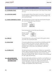
MEAT GUIDE<br />
P/N 19762<br />
FEED END HEAT SHIELD<br />
P/N 20468<br />
PATTY SHIELD<br />
P/N 16691<br />
F. PARTS LOCATION DRAWINGS<br />
Feed End View<br />
FEEDER COVER<br />
P/N 17066<br />
PUSH BAR FEEDER<br />
P/N 22348<br />
WIRE BELT FEEDER<br />
P/N 22353<br />
FEEDER HOUSING<br />
P/N 22295<br />
LOWER HEAT REFLECTOR<br />
P/N 20472<br />
WARMING PAN<br />
SHIELD<br />
P/N 16840<br />
GREASE PAN<br />
P/N 18546<br />
28 <strong>Nieco</strong> Corporation - Model <strong>JF94E</strong> <strong>CE</strong>
IN<strong>CE</strong>NDALYST<br />
P/N 20860<br />
HOOD, CHIMNEY<br />
P/N 22293<br />
F. PARTS LOCATION DRAWINGS<br />
Discharge, Side & Top View<br />
UPPER HEAT REFLECTOR<br />
P/N 19099<br />
ROD BELT, 5’ PER SIDE<br />
P/N 6035<br />
GREASE BOX<br />
P/N 16382<br />
GREASE THROUGH<br />
P/N 16307<br />
HEAT SHIELD,<br />
DISCHARGE<br />
P/N 20469<br />
PRODUCT RETURN SLIDE<br />
P/N 20474<br />
STRIPPER BLADE<br />
P/N 18919<br />
29 <strong>Nieco</strong> Corporation - Model <strong>JF94E</strong> <strong>CE</strong>
THERMOCOUPLE<br />
P/N 18861<br />
F. PARTS LOCATION DRAWINGS<br />
Right Side Control Box<br />
ELEMENT, 1000W, 380V<br />
P/N 20295<br />
CONTROL SPEED<br />
P/N 15161-B<br />
RELAY, 8A<br />
P/N 18093<br />
RELAY, 20A<br />
P/N 20724<br />
30 <strong>Nieco</strong> Corporation - Model <strong>JF94E</strong> <strong>CE</strong><br />
TOOL,<br />
CLEANING<br />
P/N 9128<br />
BLOWER<br />
P/N 18447<br />
ELEMENT,<br />
1000W, 230V<br />
P/N 20418<br />
CIRCUIT BREAKER,<br />
20A<br />
P/N 11965<br />
CIRCUIT BREAKER,<br />
25A<br />
P/N 19161<br />
CONTROL, TEMP<br />
P/N 19235
ELEMENT, 1000W, 380V<br />
P/N 20295<br />
F. PARTS LOCATION DRAWINGS<br />
Left Side Control Box<br />
THERMOCOUPLE<br />
P/N 18861<br />
SCR BASE<br />
P/N 4136<br />
CONTROL, BELT SPEED<br />
P/N 13727-B<br />
INDICATOR LIGHT<br />
P/N 4402<br />
SWITCH, 50A<br />
P/N 15480<br />
31 <strong>Nieco</strong> Corporation - Model <strong>JF94E</strong> <strong>CE</strong><br />
CONTROL, TEMP<br />
P/N 19235<br />
RELAY<br />
P/N 15329<br />
CIRCUIT BREAKER, 25A<br />
P/N 19161<br />
SPROCKET, 35B32<br />
P/N 13699<br />
SPROCKET, 35C19<br />
P/N 11081<br />
BLOWER<br />
P/N 18447<br />
SPROCKET, 35B10<br />
P/N 17899
F. PARTS LOCATION DRAWINGS<br />
Motor Control Box (On discharge of broiler)<br />
GEAR MOTOR, DC,<br />
BRUSHLESS<br />
P/N 17932<br />
POWER<br />
CONNECTION,<br />
TERMINAL<br />
BLOCK<br />
P/N 17382<br />
CONTACTOR,<br />
4 POLE, 24V<br />
P/N 18889<br />
TRANSFORMER,<br />
230/115-24V<br />
P/N 19001<br />
RECTIFIER<br />
P/N 12725<br />
FUSE HOLDER<br />
P/N 4405-31<br />
FUSE, 2AMP<br />
P/N 4621-02<br />
32 <strong>Nieco</strong> Corporation - Model <strong>JF94E</strong> <strong>CE</strong>
CLUTCH ASSEMBLY<br />
P/N 15882<br />
F. PARTS LOCATION DRAWINGS<br />
Clutch Assembly<br />
SPROCKET, CLUTCHED,<br />
BELLEVILLE SPRING<br />
P/N 14900<br />
BEARING, SHOULDER<br />
WASHER, LARGE,<br />
FEEDER DRIVE<br />
P/N 14896<br />
33 <strong>Nieco</strong> Corporation - Model <strong>JF94E</strong> <strong>CE</strong>
WIREBELT, 12” WIDE<br />
P/N 17409<br />
BUSHING FLANGED<br />
P/N 19913<br />
ROLL PIN<br />
P/N 11114<br />
F. PARTS LOCATION DRAWINGS<br />
Feeder Assembly<br />
COLLAR, SHAFT<br />
P/N 6099<br />
BUSHING<br />
FLANGED<br />
P/N 19913<br />
SHAFT, DRIVE<br />
P/N 22298<br />
SHAFT, DRIVE,<br />
P/N 22298<br />
SPROCKET,<br />
ROLLER CHAIN, 12T<br />
P/N 20883<br />
SPROCKET, ROLLER<br />
CHAIN, 12T<br />
P/N 20883<br />
COLLAR, SHAFT<br />
P/N 6099<br />
COUPLE, DRIVE<br />
P/N 11194<br />
BUSHING<br />
FLANGED<br />
P/N 19913<br />
BUSHING FLANGED<br />
P/N 19913<br />
SPROCKET,<br />
WIREBELT, 24T<br />
P/N 20882<br />
PUSHBAR FEEDER<br />
P/N 15617<br />
ROLL PIN<br />
P/N 11114<br />
CHAIN, LADDER, 6 SETS<br />
OF 17 LINKS<br />
P/N 11381<br />
COUPLE, DRIVE<br />
P/N 11194<br />
TENSIONER, PUSHBAR,<br />
PTFE, LEFT<br />
P/N 22296<br />
34 <strong>Nieco</strong> Corporation - Model <strong>JF94E</strong> <strong>CE</strong><br />
TENSIONER, PUSHBAR,<br />
PTFE, RIGHT<br />
P/N 22297
OCTOBER 11, 2011<br />
PART NO. DESCRIPTION<br />
G. PARTS REPLA<strong>CE</strong>MENT LIST<br />
AIR SYSTEM<br />
20909 CONNECTOR, FLEX, 3⁄4 X 16” - ASSY<br />
20821 AIR TUBE, MANIFOLD, BLOWER - WLDMT<br />
19764 HEATER HOSE, 3/4” ID X 2”<br />
19040 AIR BOX, FRONT, 13.38“, JF-G/E - WLDMT<br />
19022 AIR BOX, REAR, FLAT, 13.38”“, JF-E - WLDMT<br />
18447 BLOWER, HIGH PRESSURE, 24VDC, 2 WIRE<br />
BELT DRIVE SYSTEM & BEARINGS<br />
17932 GEAR MOTOR, DC, BRUSHLESS, OFFSET SHAFT<br />
17907 BEARING, SLEEVE, 3/8”, SNAP-IN<br />
17906 BRACKET, SUPPORT, 3/8“ MOTOR SHAFT<br />
17899 SPROCKET, 35B10, 3/8” BORE<br />
20430 COVER, CHAIN/FINGER GUARD, DRIVE SHAFT, JF<br />
17907 BEARING, SLEEVE, 3/8”, SNAP-IN<br />
18998 DRIVE SHAFT, DUAL 13“ BELT, JF - ASSY<br />
13699 SPROCKET, 35B32, 3/4” ID<br />
18997 DRIVE SHAFT, OUTER TUBE, 13“ BELT - WLDMT<br />
18996 DRIVE SHAFT, 33.33“, 13” BELT, JF - WLDMT<br />
18919 STRIPPER BLADE, FIXED, DUAL 13” BELT, JF<br />
15655 ROD, KEYED 5/8“ X 16-3/4“ LONG, 13” BELT - WLDMT<br />
6049 BEARING, PTFE,1“W X 1-7/8“H, Ø5/8“ SHAFT<br />
6047 BEARING, PTFE,1“W X 1-7/8”H, Ø3/4“ SHAFT<br />
6046 BEARING, PTFE,1”W X 1-7/8“H, Ø1-1/4“ SHAFT<br />
6035 ROD BELT,7GA,5/8“PITCH,13“ WIDE<br />
6027 CHAIN, ROLLER, #35<br />
20430 COVER, CHAIN/FINGER GUARD, DRIVE SHAFT, JF<br />
22293 HOOD, CHIMNEY, IN<strong>CE</strong>NDALYST, JF - WLDMT<br />
22291 HEAT REFLECTOR, ELEMENTS, UPPER, JF94/84<br />
20474 SLIDE, 4 LANE, 28.5” FRAME, JF - WLDMT<br />
20472 REFLECTOR, ELEMENT, LOWER, 12.5” W - WLDMT<br />
20469 HEAT SHIELD, REAR, 28.5’’ FRAME, JF<br />
20468 HEAT SHIELD, FEEDER/FRAME, 28.5“ FRAME, JF<br />
19099 HEAT REFLECTOR, UPPER, <strong>JF94E</strong><br />
18546 GREASE PAN, NON VENTED - 28.5“ FRAME<br />
17052 TRAY, GREASE DRIP - 28.5“ FRAME<br />
16946 FRAME, SUPPORT, HOLDING PAN, 4 LANE, MPB<br />
16840 SHIELD, HEAT, SHUTTLE<br />
16794 RACK, STACKING, PATTY PAN<br />
16382 PAN, HOTEL, 1/9 X 4” DEEP<br />
16307 TRAY, SLUDGE - 28.5” FRAME - WLDMT<br />
9128 TOOL, SHAFT CLEANING<br />
35 <strong>Nieco</strong> Corporation - Model <strong>JF94E</strong> <strong>CE</strong>
G. PARTS REPLA<strong>CE</strong>MENT LIST<br />
ELECTRICAL ELEMENTS & CONTROLS<br />
22288 COVER, ENCLOSURE, ELEC/MOTORS, REAR, JF<br />
22287 COVER, ENCLOSURE, ELEC/AIR, JF-E, R<br />
22286 COVER, ENCLOSURE, ELEC/AIR, JF-E, L<br />
22285 ENCLOSURE, ELEC/MOTOR, REAR, JF-E - ASSY<br />
22278 ENCLOSURE, ELEC/AIR, JF94/84E, RIGHT - ASSY<br />
20876 CONTROL GUARD, 7”“ LONG, ELECTRICAL BOX<br />
20724 RELAY, SOLID STATE, 20A, 600V, DC COIL<br />
19161 CIRCUIT BREAKER, 277/480V, 25A. 3 POLE<br />
19235 CONTROL, DIGITAL TEMP, 24VAC, SSR OUT<br />
15161-B CONTROL, SPEED MULTI-CHANNEL, VERTICAL<br />
19161 CIRCUIT BREAKER, 277/480V, 25A. 3 POLE<br />
11965 CIRCUIT BREAKER, 20A<br />
18092 RELAY BASE, DIN MOUNT, 8 PIN<br />
18093 RELAY, 250VAC, 24V COIL, 8A, 8 PIN<br />
18686 TERMINAL BLOCK, 4 X 4MM, SC, GRAY<br />
4621-02 FUSE, 2 AMP<br />
4405-31 TERMINAL BLOCK, FUSE HOLDER, TYPE M<br />
19001 TRANSFORMER, 230/115-24V, 7.3A<br />
18889 CONTACTOR, 4 POLE, 24V, COIL<br />
12725 RECTIFIER, SINGLE PHASE BRIDGE, 25A 200V<br />
4621-02 FUSE, 2 AMP<br />
15480 SWITCH, ROCKER, 50A CIRCUIT BREAKER<br />
13727-B CONTROL, BRUSHLESS MOTOR<br />
IDLER SPROCKET, 35C19, 3/8”“ BORE<br />
4402 INDICATOR LIGHT, GREEN, 28V<br />
4136 SCR BASE<br />
20418 ELEMENT - 31’’, 1000W, 230V, Ø.55<br />
20295 ELEMENT - 17.5”“, 1000W, 380V, Ø.49 - WLDMT (<strong>CE</strong>)<br />
20291 ELEMENT - 17.5”“, 1000W, 208V, Ø.49 - WLDMT (DOMESTIC)<br />
18168 CABLE, MOTOR, 4 WIRE W/CONNECTOR<br />
18861 THERMOCOUPLE PROBE, 1.88”, TYPE J, 48“ LEADS<br />
13579 SWTCH, MOTOR REVERSING<br />
18687 END COVER, 2 X 4MM, SC, GRAY<br />
4405-01 END STOP, GRAY (103 002.26)<br />
22269 ENCLOSURE, ELEC/AIR, JF94/84E, LEFT - ASSY<br />
SHEET METAL PARTS<br />
16403 BRACKET, MOUNTING, STRIPPER BLADE - RIGHT<br />
16402 BRACKET, MOUNTING, STRIPPER BLADE - LEFT<br />
15689 ROD, CROSS SUPPORT - .63” X 28.5”<br />
6300 ROD, CROSS SUPPORT - 5/8“ X 26,875”<br />
6028 COLLAR, SET, 5/8” BORE<br />
16838 BRACKET, TENSIONING, ROD BELT<br />
36 <strong>Nieco</strong> Corporation - Model <strong>JF94E</strong> <strong>CE</strong>
G. PARTS REPLA<strong>CE</strong>MENT LIST<br />
18910 SUPPORT, ELEMENT/AIR, UPPER, REAR, JF-E<br />
19610 BEARING, ALUM/BRZ, 5/8” SHAFT X 1.44” WIDE<br />
20300 BRACKET, FEEDER SUPPORT, JF, LEFT<br />
20301 BRACKET, FEEDER SUPPORT, JF, RIGHT<br />
20312 SUPPORT, BEARING, <strong>CE</strong>NTER, JF-E - WLDMT<br />
20417 SHIELD, PATTY WARMER, JF - WLDMT<br />
20419 SUPPORT, BELT (1/8” SS PIPE, 2” LONG)<br />
20309 BRACKET, REFLECTOR/SCRAPER, JF-E - WLDMT<br />
FEEDER<br />
22214 FEEDER W/DRIVES, DUAL 13”, PB/WB, JF<br />
22353 DRIVE UNIT, WIREBELT, 13” BELT, RH - ASSY<br />
22298 SHAFT, DRIVE, PB/WB, 14.53” L, 13” ROD BELT<br />
22297 TENSIONER, PUSH BAR, PTFE, RIGHT - ASSY<br />
22296 TENSIONER, PUSH BAR, PTFE, LEFT - ASSY<br />
20883 SPROCKET, ROLLER CHAIN, 12T, 3/8” BORE<br />
15617 PUSH-BAR, 13“ ROD BELT - WLDMT<br />
11478 BUSHING, FLANGED, 3/8” SHAFT, W/FLAT<br />
11381 CHAIN,LADER,353” PITCH, 13 GA<br />
11194 COUPLER, DRIVE, 1/4” SQ X 3/8” ID<br />
22347 PLATFORM, TRIPLE PUSH-BAR, 13“ BELT<br />
22353 DRIVE UNIT, WIREBELT, 13” BELT, RH - ASSY<br />
22352 SHAFT, Ø1/2”, 1/4-20 TAPPED X 12.88”<br />
22351 TENSIONER, WIREBELT, 13” BELT - WLDM<br />
20882 SPROCKET, WIREBELT, 24T, Ø3/8” BORE<br />
19913 BUSHING, FLANGED, Ø3^8’’ SHAFT X .275’’, W/FLAT<br />
17409 WIRE BELT, 72 X .050 MESH X 12” WIDE X 3 SPA<strong>CE</strong>S<br />
11114 ROLL PIN, Ø1/8 X 1”.SS<br />
6099 COLLAR, SHAFT, SET SCREW, 3/8” BORE<br />
22349 PLATFORM, WIREBELT, 13“ BELT, JF<br />
19762 FRAME, 1/2” TO 1“ PATTY, 13” BELT - ASSY<br />
17494 BRACKET, CLUTCH RESTRAINT, FEEDER DRIVE<br />
17066 COVER, FEEDER, DUAL 13” - MPB<br />
16691 COVER, FEEDER, 2 LANE, FLEX SIDE<br />
22295 ENCLOSURE, DUAL 13” FEEDER, JF - WLDMT<br />
20884 DRIVE ASSY W/CLUTCH, 15T FEEDER, UNIV<br />
20504 COVER, FEEDER DRIVE/CLUTCH ASSY, JF<br />
11608 KNOB, BLACK, INSERT, 10-32<br />
6053 OFFSET LINK, #35 ROLLER CHAIN<br />
6048 MASTER LINK, # 35 ROLLER CHAIN<br />
6037 SPROCKET, ROLLERCHAIN, 35B 15, 5/8” BORE<br />
6027 CHAIN, ROLLER, #35<br />
14900 SPROCKET, CLUTCHED, 13T, BELLEVILLE SPRING<br />
14896 BEARING, SHOULDER WASHER, LARGE, FEEDER DRIVE<br />
10627 BEARING CLIP, 1/2“ ID,12 THK<br />
37 <strong>Nieco</strong> Corporation - Model <strong>JF94E</strong> <strong>CE</strong>
G. PARTS REPLA<strong>CE</strong>MENT LIST<br />
MIS<strong>CE</strong>LLANEOUS<br />
20860 IN<strong>CE</strong>NDALYST, 15.19“ X 8“ X 1.5“, 29 CPI<br />
22400 SPARE KIT<br />
22342 HEAVY DUTY SPARES KIT<br />
38 <strong>Nieco</strong> Corporation - Model <strong>JF94E</strong> <strong>CE</strong>
REV. DESCRIPTION DATE BY<br />
A Initial Release 8-Jul-11 PB<br />
B Updated flex (right) side 12-Aug-11 PB<br />
element w iring<br />
C Replaced Broil Stabilizer, w as 16035 26-Sep-11 PB<br />
D Corrected main side element w iring. 29-Sep-11 PB<br />
E Corrected flex side element w iring. 6-Oct-11 PB<br />
F Changed Main Side element w iring.16-Nov-11 PB<br />
G, H Changed Flex element w iring. 3-Dec-11 PB<br />
J Changed Flex element w iring. 6-Jan-12 KK<br />
K Changed Main & Warming Elements 6-Feb-12 KK<br />
Page 1 Left Side<br />
Control Box<br />
B<br />
Feed End<br />
B<br />
1<br />
Element Connection Wires 12 ga. TGGT<br />
8 7 R 6 5<br />
4 3 2<br />
R<br />
H. WIRING DIAGRAM - Main Side<br />
B<br />
R<br />
B<br />
B<br />
R<br />
Y<br />
R<br />
Heating Elements (9)<br />
P/N 20295<br />
Control Settings:<br />
Belt Speed Control<br />
B = 36<br />
P/N 13727-B<br />
G<br />
C = 450<br />
Socket Base<br />
5 4<br />
TLL = 1:00<br />
P/N 4136<br />
THH = 7:00 6<br />
3<br />
DIR = L<br />
7<br />
2<br />
B W<br />
8 1<br />
16 15 14 13 12 11 10 9<br />
R<br />
18 17<br />
B<br />
R<br />
R<br />
Y<br />
R<br />
B<br />
To Motor Reverse<br />
Button<br />
Y #12 TGGT<br />
Motor Reverse Switch<br />
P/N 13579<br />
G<br />
Br<br />
12<br />
B #10<br />
B #10<br />
B<br />
R<br />
Solid State Relay<br />
50A<br />
P/N 15329<br />
Broil<br />
Stabilizer Control<br />
P/N 19235<br />
17 16 11<br />
R<br />
B<br />
B<br />
R<br />
R<br />
B<br />
39<br />
Br<br />
G<br />
R<br />
W<br />
6<br />
7<br />
8<br />
9<br />
10<br />
L2 L3<br />
Circuit Breaker, 3 Pole 25A<br />
P/N 19161<br />
From Broil Stabilizer<br />
Control<br />
A2 A1<br />
(-) (+)<br />
13 14<br />
1<br />
2<br />
L1<br />
L1 T1<br />
3<br />
4<br />
18<br />
R<br />
11 12<br />
14<br />
R<br />
5<br />
To Motor Control, pin 3<br />
R<br />
B<br />
Pur<br />
W<br />
L2<br />
L1<br />
11<br />
10<br />
B<br />
B<br />
Thermocouple<br />
P/N 18861<br />
Green Light<br />
24V<br />
P/N 4402<br />
B #10<br />
9<br />
8<br />
4<br />
To Contactor Coil<br />
3<br />
B #10<br />
B #10<br />
B #10<br />
W<br />
Pur<br />
7<br />
6<br />
5<br />
Main Power<br />
Switch<br />
P/N 15480<br />
Or<br />
Bl<br />
1 2<br />
From Transformer<br />
24VAC from terminal<br />
block<br />
This document is the property of <strong>Nieco</strong><br />
Corporation. Reproduction or release without<br />
express permission is prohibited<br />
<strong>Nieco</strong> Corporation - Model <strong>JF94E</strong> <strong>CE</strong><br />
24VDC from rectifier<br />
Wiring Diagram<br />
Drawn Date Model Dwg No.<br />
Rev.<br />
PB 30Jun11 JF94/84E, <strong>CE</strong>, 380-400V 20110 K<br />
Page 1 of 3<br />
Motor Cable<br />
Low Voltage<br />
Conduit<br />
High Voltage<br />
Conduit
R<br />
Y<br />
Y<br />
Page 2 Right Side<br />
Control Box<br />
B<br />
Heating Elements (9)<br />
P/N 20295<br />
13 14<br />
15 16<br />
17 18<br />
12<br />
11<br />
Feed End<br />
Control<br />
Settings:<br />
B = 36<br />
C = 450<br />
TLL = 1:00<br />
THH = 7:00<br />
DIR = L<br />
Multi-Product<br />
Control<br />
P/N 15161-B<br />
B<br />
Y<br />
Y<br />
B<br />
B<br />
B<br />
R<br />
Element Connection Wires 12 ga. TGGT<br />
Burner<br />
24VAC<br />
Y<br />
Y<br />
Y<br />
H. WIRING DIAGRAM - Flex Side<br />
To motor Reverse<br />
Button<br />
Heater<br />
24VDC<br />
+<br />
-<br />
Or<br />
B<br />
10<br />
3 4<br />
5 6<br />
7 8<br />
9<br />
2<br />
1<br />
B<br />
Y<br />
Y<br />
1<br />
7 6 5 4 3 2<br />
R<br />
Motor Reverse Switch<br />
P/N 13579<br />
Br<br />
W<br />
B<br />
G<br />
R<br />
W<br />
R<br />
B<br />
Circuit Breaker, 20A<br />
P/N 11965<br />
To Multi Product<br />
Control, pin 3<br />
Circuit Breaker, 3 Pole 25A<br />
P/N 19161<br />
Warmer Element<br />
P/N 20418<br />
19 20<br />
Bl<br />
Y<br />
20<br />
Broil<br />
Stabilizer Control<br />
P/N 19235<br />
19<br />
18<br />
Bl<br />
24V Relay<br />
For blower<br />
Relay P/N 18093<br />
Base P/N 18092<br />
R<br />
Y<br />
B #10<br />
B #10<br />
B<br />
B<br />
Br<br />
W<br />
R<br />
Y<br />
R<br />
B<br />
R<br />
B<br />
Or<br />
B<br />
Or<br />
W<br />
R<br />
Solid State Relay<br />
20A (3)<br />
P/N 20724<br />
A2 A1<br />
(-) (+)<br />
A2 A1<br />
(-) (+)<br />
A2 A1<br />
(-) (+)<br />
6<br />
7<br />
8<br />
9<br />
10<br />
13 14<br />
1<br />
2<br />
N<br />
L1 L2 L3<br />
T1 L1<br />
Terminal Blocks (7)<br />
P/N 18686<br />
B #12 TG G T<br />
T1 L1<br />
10<br />
Y #12 TG G T<br />
T1 L1<br />
Y<br />
Bl<br />
3<br />
Y #12 B<br />
3<br />
4<br />
11 12<br />
5<br />
Y #12 TG G T<br />
Thermocouple<br />
P/N 18861<br />
9<br />
Bl<br />
Y<br />
B #10<br />
R<br />
B<br />
B<br />
Bl<br />
Y<br />
Y #12<br />
R<br />
Or<br />
Br<br />
Y<br />
Bl #12<br />
B #10<br />
B #10<br />
B #10<br />
16<br />
15<br />
18<br />
17<br />
14<br />
13<br />
12<br />
40 <strong>Nieco</strong> Corporation - Model <strong>JF94E</strong> <strong>CE</strong><br />
24VAC from transformer<br />
24VDC from rectifier<br />
Low Voltage<br />
Conduit Motor Box<br />
Motor Cable<br />
High Voltage<br />
Conduit<br />
This document is the property of <strong>Nieco</strong><br />
Corporation. Reproduction or release without<br />
express permission is prohibited<br />
Wiring Diagram<br />
Drawn Date Model Dwg No.<br />
Rev.<br />
PB 30Jun11 JF94/84E, <strong>CE</strong>, 380-400V 20110 K<br />
Page 2 of 3<br />
To High Pressure Blower
Page 3 Motor Box<br />
H. WIRING DIAGRAM - Motor Box<br />
To Left Side<br />
Control Box pg. 1<br />
To Right Side<br />
Control Box pg. 2<br />
24VDC to left control box<br />
High Voltage<br />
Conduit<br />
Low Voltage<br />
Conduit<br />
Low Voltage<br />
Conduit<br />
24VAC to left control box<br />
High Voltage<br />
Conduit<br />
14<br />
13<br />
12<br />
To Main Switch<br />
10 ga. Black<br />
12 ga. Blue<br />
to Right Side<br />
Circuit Breakers<br />
24VAC to right<br />
control box<br />
From Main Switch<br />
24VDC to right<br />
control box<br />
W<br />
Pur<br />
Bl #12<br />
7<br />
6<br />
5<br />
4<br />
3<br />
B<br />
10 ga. Black to Left Side<br />
Circuit Breakers<br />
B #10<br />
B #10<br />
B #10<br />
Motor (2)<br />
P/N 17932<br />
Bl #12<br />
Pur<br />
W<br />
15 10 16 11 17 8 18 9<br />
Y<br />
1<br />
Bl<br />
L3<br />
L2<br />
L1<br />
2<br />
Or<br />
Bridge Rectifier<br />
PRI SEC<br />
P/N 12725 6 12<br />
notch<br />
Fuseholder<br />
5 11<br />
+ ~<br />
P/N 4405-31<br />
2 Amp Fuse 4 10<br />
3 9<br />
~<br />
P/N 4621-02<br />
-<br />
2 8<br />
1 7<br />
Pur<br />
Bl<br />
W<br />
Y<br />
R<br />
Or<br />
B<br />
Br<br />
1L1 3L2 5L3 7L4<br />
N<br />
Coil<br />
8T4<br />
6T3<br />
4T2<br />
2T1<br />
Bl<br />
B<br />
Y<br />
R<br />
Note: Label terminal<br />
blocks<br />
10 mm Terminal Blocks<br />
Gray P/N 4405-16<br />
Blue P/N 4405-17<br />
Ground P/N 4405-18<br />
Bl #12<br />
Y<br />
B #10<br />
B #10<br />
B #10<br />
B<br />
Transformer<br />
P/N 19001<br />
Y<br />
Pur<br />
Bl<br />
W<br />
R<br />
Y<br />
B<br />
Note: Apply label with<br />
fuse rating next to<br />
fuseholder<br />
4 Pole Contactor<br />
50A, 24V Coil<br />
P/N 18889<br />
High Pressure Blower<br />
P/N 18447<br />
41 <strong>Nieco</strong> Corporation - Model <strong>JF94E</strong> <strong>CE</strong><br />
B<br />
R<br />
B<br />
R<br />
High Pressure Blower<br />
P/N 18447<br />
This document is the property of <strong>Nieco</strong><br />
Corporation. Reproduction or release without<br />
express permission is prohibited<br />
Wiring Diagram<br />
Drawn Date Model Dwg No.<br />
Rev.<br />
PB 30Jun11 JF94/84E, <strong>CE</strong>, 380-400V 20110 K<br />
Page 3 of 3
AUTOMATIC BROILER<br />
Model <strong>JF94E</strong><br />
DIMENSIONS INCH MM<br />
Length 35.48 901<br />
Height 64.02 1626<br />
Width 40.11 1019<br />
ENERGY<br />
Electrical connection (specify exact voltage)<br />
<strong>CE</strong> 380-415V 3Ø 25A 19kW<br />
Calculated average consumption: 16kW<br />
WEIGHT LBS KG<br />
Shipping 690 313<br />
Broiler on Stand 565 256<br />
CAUTION<br />
All electrical connections must be<br />
in accordance with local electrical<br />
codes and any other applicable<br />
codes.<br />
CAUTION<br />
Do not operate the broiler at gas<br />
pressures other than those stated<br />
here. Doing so will affect the operation<br />
of your broiler.<br />
I. SPECIFICATIONS<br />
1663<br />
65.47<br />
1626<br />
64.02<br />
853<br />
33.57<br />
ELT<br />
758<br />
29.83<br />
624<br />
24.57<br />
1076<br />
42.35<br />
1019<br />
40.11<br />
910<br />
35.82<br />
556<br />
21.91<br />
901<br />
35.48<br />
42 <strong>Nieco</strong> Corporation - Model <strong>JF94E</strong> <strong>CE</strong><br />
167<br />
6.58<br />
.<br />
.<br />
1378<br />
54.25<br />
BROIL BELT<br />
1
<strong>Nieco</strong> Corporation<br />
7950 Cameron Drive<br />
Windsor, CA 95492<br />
+1-707-284-7100<br />
+1-707-284-7430 Fax<br />
www.nieco.com<br />
sales@nieco.com • service@nieco.com<br />
© 2011 <strong>Nieco</strong> Corporation All Rights Reserved<br />
Printed in the U.S.A