AUTOMATIC TRANSAXLE UNIT
AUTOMATIC TRANSAXLE UNIT
AUTOMATIC TRANSAXLE UNIT

You also want an ePaper? Increase the reach of your titles
YUMPU automatically turns print PDFs into web optimized ePapers that Google loves.
http://www.ondemand5.com/mric/common/asp/printart.aspx<br />
<strong>AUTOMATIC</strong> <strong>TRANSAXLE</strong> <strong>UNIT</strong><br />
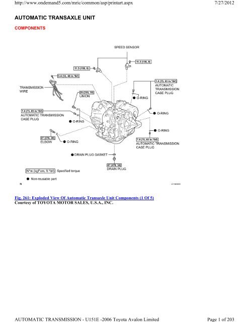
COMPONENTS<br />
Fig. 261: Exploded View Of Automatic Transaxle Unit Components (1 Of 5)<br />
Courtesy of TOYOTA MOTOR SALES, U.S.A., INC.<br />
<strong>AUTOMATIC</strong> TRANSMISSION - U151E -2006 Toyota Avalon Limited<br />
7/27/2012<br />
Page 1 of 203
http://www.ondemand5.com/mric/common/asp/printart.aspx<br />
Fig. 262: Exploded View Of Automatic Transaxle Unit Components (2 Of 5)<br />
Courtesy of TOYOTA MOTOR SALES, U.S.A., INC.<br />
<strong>AUTOMATIC</strong> TRANSMISSION - U151E -2006 Toyota Avalon Limited<br />
7/27/2012<br />
Page 2 of 203
http://www.ondemand5.com/mric/common/asp/printart.aspx<br />
Fig. 263: Exploded View Of Automatic Transaxle Unit Components (3 Of 5)<br />
Courtesy of TOYOTA MOTOR SALES, U.S.A., INC.<br />
<strong>AUTOMATIC</strong> TRANSMISSION - U151E -2006 Toyota Avalon Limited<br />
7/27/2012<br />
Page 3 of 203
http://www.ondemand5.com/mric/common/asp/printart.aspx<br />
Fig. 264: Exploded View Of Automatic Transaxle Unit Components (4 Of 5)<br />
Courtesy of TOYOTA MOTOR SALES, U.S.A., INC.<br />
<strong>AUTOMATIC</strong> TRANSMISSION - U151E -2006 Toyota Avalon Limited<br />
7/27/2012<br />
Page 4 of 203
http://www.ondemand5.com/mric/common/asp/printart.aspx<br />
Fig. 265: Exploded View Of Automatic Transaxle Unit Components (5 Of 5)<br />
Courtesy of TOYOTA MOTOR SALES, U.S.A., INC.<br />
DISASSEMBLY<br />
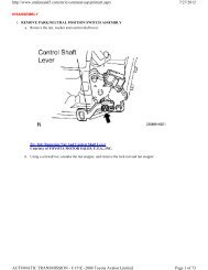
1. REMOVE PARK/NEUTRAL POSITION SWITCH ASSEMBLY<br />
a. Remove the nut, washer and control shaft lever.<br />
<strong>AUTOMATIC</strong> TRANSMISSION - U151E -2006 Toyota Avalon Limited<br />
7/27/2012<br />
Page 5 of 203
http://www.ondemand5.com/mric/common/asp/printart.aspx<br />
Fig. 266: Removing Nut And Control Shaft Lever<br />
Courtesy of TOYOTA MOTOR SALES, U.S.A., INC.<br />
b. Using a screwdriver, unstake the nut stopper, and remove the lock nut and nut stopper.<br />
Fig. 267: Removing Lock Nut And Nut Stopper<br />
Courtesy of TOYOTA MOTOR SALES, U.S.A., INC.<br />
<strong>AUTOMATIC</strong> TRANSMISSION - U151E -2006 Toyota Avalon Limited<br />
7/27/2012<br />
Page 6 of 203
http://www.ondemand5.com/mric/common/asp/printart.aspx<br />
c. Remove the 2 bolts and pull out the park/neutral position switch.<br />
2. REMOVE BREATHER PLUG HOSE<br />
a. Remove the breather plug hose from the transaxle case.<br />
Fig. 268: Removing 2 Bolts<br />
Courtesy of TOYOTA MOTOR SALES, U.S.A., INC.<br />
3. REMOVE OIL COOLER TUBE UNION (INLET OIL COOLER UNION)<br />
a. Remove the union.<br />
b. Remove the O-ring from the union.<br />
<strong>AUTOMATIC</strong> TRANSMISSION - U151E -2006 Toyota Avalon Limited<br />
7/27/2012<br />
Page 7 of 203
http://www.ondemand5.com/mric/common/asp/printart.aspx<br />
Fig. 269: Identifying Union And O-Ring<br />
Courtesy of TOYOTA MOTOR SALES, U.S.A., INC.<br />
4. REMOVE OIL COOLER TUBE UNION (OUTLET OIL COOLER UNION)<br />
a. Remove the elbow.<br />
b. Remove the O-ring from the elbow.<br />
<strong>AUTOMATIC</strong> TRANSMISSION - U151E -2006 Toyota Avalon Limited<br />
7/27/2012<br />
Page 8 of 203
http://www.ondemand5.com/mric/common/asp/printart.aspx<br />
Fig. 270: Identifying Elbow And O-Ring<br />
Courtesy of TOYOTA MOTOR SALES, U.S.A., INC.<br />
5. REMOVE SPEED SENSOR<br />
a. Remove the 2 bolts and the 2 speed sensors from the transaxle assembly.<br />
Fig. 271: Removing Speed Sensor<br />
Courtesy of TOYOTA MOTOR SALES, U.S.A., INC.<br />
6. REMOVE <strong>TRANSAXLE</strong> CASE NO. 1 PLUG<br />
a. Remove the 4 transaxle case No.1 plugs from the transaxle case.<br />
b. Remove the 4 O-rings from the 4 transaxle case No.1 plugs.<br />
<strong>AUTOMATIC</strong> TRANSMISSION - U151E -2006 Toyota Avalon Limited<br />
7/27/2012<br />
Page 9 of 203
http://www.ondemand5.com/mric/common/asp/printart.aspx<br />
Fig. 272: Locating 4 Transaxle Case No.1 Plugs To Transaxle Case<br />
Courtesy of TOYOTA MOTOR SALES, U.S.A., INC.<br />
7. FIX <strong>AUTOMATIC</strong> <strong>TRANSAXLE</strong> ASSEMBLY<br />
a. Fix the transaxle assembly.<br />
Fig. 273: View Of Oil Pan And 18 Bolts To Transaxle Case<br />
Courtesy of TOYOTA MOTOR SALES, U.S.A., INC.<br />
<strong>AUTOMATIC</strong> TRANSMISSION - U151E -2006 Toyota Avalon Limited<br />
7/27/2012<br />
Page 10 of 203
http://www.ondemand5.com/mric/common/asp/printart.aspx<br />
8. REMOVE <strong>AUTOMATIC</strong> <strong>TRANSAXLE</strong> OIL PAN SUB-ASSEMBLY<br />
a. Remove the 18 bolts, oil pan and gasket.<br />
Fig. 274: Identifying Oil Pan Bolts<br />
Courtesy of TOYOTA MOTOR SALES, U.S.A., INC.<br />
b. Remove the 2 magnets from the oil pan.<br />
<strong>AUTOMATIC</strong> TRANSMISSION - U151E -2006 Toyota Avalon Limited<br />
7/27/2012<br />
Page 11 of 203
http://www.ondemand5.com/mric/common/asp/printart.aspx<br />
Fig. 275: Removing 2 Magnets From Oil Pan<br />
Courtesy of TOYOTA MOTOR SALES, U.S.A., INC.<br />
9. INSPECT TRANSMISSION OIL CLEANER MAGNET<br />
a. Remove the magnets and use them to collect any steel chips. Examine the chips and particles in the pan and on the<br />
magnet to determine what type of wear has occurred in the transaxle:<br />
Result:<br />
Steel (magnetic):<br />
Wear of the bearing, gear and plate<br />
Brass (non-magnetic):<br />
Wear of the bushing<br />
<strong>AUTOMATIC</strong> TRANSMISSION - U151E -2006 Toyota Avalon Limited<br />
7/27/2012<br />
Page 12 of 203
http://www.ondemand5.com/mric/common/asp/printart.aspx<br />
Fig. 276: Collecting Steel Chips From Magnets<br />
Courtesy of TOYOTA MOTOR SALES, U.S.A., INC.<br />
10. DISCONNECT TRANSMISSION WIRE<br />
a. Remove the 7 connectors from the shift solenoid valves.<br />
b. Remove the bolt, lock plate and temperature sensor.<br />
<strong>AUTOMATIC</strong> TRANSMISSION - U151E -2006 Toyota Avalon Limited<br />
7/27/2012<br />
Page 13 of 203
http://www.ondemand5.com/mric/common/asp/printart.aspx<br />
Fig. 277: Disconnecting Transmission Wire<br />
Courtesy of TOYOTA MOTOR SALES, U.S.A., INC.<br />
11. REMOVE TRANSMISSION WIRE<br />
a. Remove the bolt and transmission wire from the transaxle case.<br />
Fig. 278: Removing Transmission Wire<br />
Courtesy of TOYOTA MOTOR SALES, U.S.A., INC.<br />
12. REMOVE VALVE BODY OIL STRAINER ASSEMBLY<br />
a. Remove the 3 bolts and oil strainer.<br />
<strong>AUTOMATIC</strong> TRANSMISSION - U151E -2006 Toyota Avalon Limited<br />
7/27/2012<br />
Page 14 of 203
http://www.ondemand5.com/mric/common/asp/printart.aspx<br />
Fig. 279: View Of Oil Strainer And Bolts<br />
Courtesy of TOYOTA MOTOR SALES, U.S.A., INC.<br />
b. Remove the O-ring from the oil strainer.<br />
<strong>AUTOMATIC</strong> TRANSMISSION - U151E -2006 Toyota Avalon Limited<br />
7/27/2012<br />
Page 15 of 203
http://www.ondemand5.com/mric/common/asp/printart.aspx<br />
Fig. 280: View Of O-Ring And Oil Strainer<br />
Courtesy of TOYOTA MOTOR SALES, U.S.A., INC.<br />
13. REMOVE TRANSMISSION VALVE BODY ASSEMBLY<br />
a. Support the valve body assembly and remove the 17 bolts and valve body assembly.<br />
<strong>AUTOMATIC</strong> TRANSMISSION - U151E -2006 Toyota Avalon Limited<br />
7/27/2012<br />
Page 16 of 203
http://www.ondemand5.com/mric/common/asp/printart.aspx<br />
Fig. 281: Locating 17 Bolts And Valve Body Assembly<br />
Courtesy of TOYOTA MOTOR SALES, U.S.A., INC.<br />
14. REMOVE GOVERNOR APPLY GASKET NO. 1<br />
a. Remove the governor apply gasket No.1 from the transaxle case.<br />
<strong>AUTOMATIC</strong> TRANSMISSION - U151E -2006 Toyota Avalon Limited<br />
7/27/2012<br />
Page 17 of 203
http://www.ondemand5.com/mric/common/asp/printart.aspx<br />
Fig. 282: Removing Governor Apply Gasket No.1<br />
Courtesy of TOYOTA MOTOR SALES, U.S.A., INC.<br />
15. REMOVE <strong>TRANSAXLE</strong> CASE 2ND BRAKE GASKET<br />
a. Remove the transaxle case 2nd brake gasket from the transaxle case.<br />
Fig. 283: Locating Transaxle Case 2nd Brake Gasket<br />
<strong>AUTOMATIC</strong> TRANSMISSION - U151E -2006 Toyota Avalon Limited<br />
7/27/2012<br />
Page 18 of 203
http://www.ondemand5.com/mric/common/asp/printart.aspx<br />
Courtesy of TOYOTA MOTOR SALES, U.S.A., INC.<br />
16. REMOVE BRAKE DRUM GASKET<br />
a. Remove the brake drum gasket from the transaxle case.<br />
Fig. 284: Identifying Brake Drum Gasket<br />
Courtesy of TOYOTA MOTOR SALES, U.S.A., INC.<br />
17. REMOVE CHECK BALL BODY<br />
a. Remove the check ball body and spring from the transaxle case.<br />
<strong>AUTOMATIC</strong> TRANSMISSION - U151E -2006 Toyota Avalon Limited<br />
7/27/2012<br />
Page 19 of 203
http://www.ondemand5.com/mric/common/asp/printart.aspx<br />
Fig. 285: View Of Check Ball, Body And Spring<br />
Courtesy of TOYOTA MOTOR SALES, U.S.A., INC.<br />
18. REMOVE C-3 ACCUMULATOR PISTON<br />
a. Remove the spring from the C-3 accumulator piston.<br />
<strong>AUTOMATIC</strong> TRANSMISSION - U151E -2006 Toyota Avalon Limited<br />
7/27/2012<br />
Page 20 of 203
http://www.ondemand5.com/mric/common/asp/printart.aspx<br />
Fig. 286: Identifying C3 Accumulator Piston Spring<br />
Courtesy of TOYOTA MOTOR SALES, U.S.A., INC.<br />
b. Apply compressed air (392 kPa, 4.0 kgf/cm 2 , 57 psi) to the oil hole and remove the C-3 accumulator piston.<br />
<strong>AUTOMATIC</strong> TRANSMISSION - U151E -2006 Toyota Avalon Limited<br />
7/27/2012<br />
Page 21 of 203
http://www.ondemand5.com/mric/common/asp/printart.aspx<br />
Fig. 287: Applying Compressed Air To Oil Hole<br />
Courtesy of TOYOTA MOTOR SALES, U.S.A., INC.<br />
NOTE: Applying compressed air may cause the piston to jump-out. When removing<br />
the piston, hold it using a waste cloth.<br />
Take care not to splash ATF when applying compressed air.<br />
c. Remove the O-ring from the C-3 accumulator piston.<br />
<strong>AUTOMATIC</strong> TRANSMISSION - U151E -2006 Toyota Avalon Limited<br />
7/27/2012<br />
Page 22 of 203
http://www.ondemand5.com/mric/common/asp/printart.aspx<br />
Fig. 288: Identifying C-3 Accumulator Piston And O-Ring<br />
Courtesy of TOYOTA MOTOR SALES, U.S.A., INC.<br />
7/27/2012<br />
19. REMOVE REVERSE CLUTCH ACCUMULATOR PISTON<br />
a. Apply compressed air (392 kPa, 4.0 kgf/cm2 , 57 psi) to the oil hole and remove the reverse accumulator piston<br />
and spring.<br />
NOTE: Applying compressed air may cause the piston to jump-out. When removing the<br />
piston, hold it using a waste cloth.<br />
Take care not to splash ATF when applying compressed air.<br />
<strong>AUTOMATIC</strong> TRANSMISSION - U151E -2006 Toyota Avalon Limited<br />
Page 23 of 203
http://www.ondemand5.com/mric/common/asp/printart.aspx<br />
Fig. 289: Removing Reverse Clutch Accumulator Piston<br />
Courtesy of TOYOTA MOTOR SALES, U.S.A., INC.<br />
b. Remove the 2 O-rings from the reverse clutch accumulator piston.<br />
Fig. 290: Removing O-Rings From Reverse Clutch Accumulator Piston<br />
Courtesy of TOYOTA MOTOR SALES, U.S.A., INC.<br />
<strong>AUTOMATIC</strong> TRANSMISSION - U151E -2006 Toyota Avalon Limited<br />
7/27/2012<br />
Page 24 of 203
http://www.ondemand5.com/mric/common/asp/printart.aspx<br />
20. REMOVE B-3 ACCUMULATOR PISTON<br />
a. Apply compressed air (392 kPa, 4.0 kgf/cm2 , 57 psi) to the oil hole and remove the B-3 accumulator piston and 2<br />
springs.<br />
NOTE: Applying compressed air may cause the piston to jump-out. When removing the<br />
piston, hold it using a waste cloth.<br />
Take care not to splash ATF when applying compressed air.<br />
Fig. 291: Removing B-3 Accumulator Piston<br />
Courtesy of TOYOTA MOTOR SALES, U.S.A., INC.<br />
b. Remove the O-ring from the B-3 accumulator piston.<br />
<strong>AUTOMATIC</strong> TRANSMISSION - U151E -2006 Toyota Avalon Limited<br />
7/27/2012<br />
Page 25 of 203
http://www.ondemand5.com/mric/common/asp/printart.aspx<br />
Fig. 292: Identifying O-Ring And B-3 Accumulator Piston<br />
Courtesy of TOYOTA MOTOR SALES, U.S.A., INC.<br />
21. REMOVE MANUAL VALVE LEVER SHAFT RETAINER SPRING<br />
a. Using needle-nose pliers, remove the manual valve lever shaft retainer spring.<br />
Fig. 293: Identifying Manual Valve Lever Shaft Retainer Spring<br />
<strong>AUTOMATIC</strong> TRANSMISSION - U151E -2006 Toyota Avalon Limited<br />
7/27/2012<br />
Page 26 of 203
http://www.ondemand5.com/mric/common/asp/printart.aspx<br />
Courtesy of TOYOTA MOTOR SALES, U.S.A., INC.<br />
22. REMOVE MANUAL DETENT SPRING SUB-ASSEMBLY<br />
a. Remove the 2 bolts, the manual detent spring sub-assembly and cover.<br />
Fig. 294: Removing Manual Detent Spring Sub-Assembly<br />
Courtesy of TOYOTA MOTOR SALES, U.S.A., INC.<br />
23. REMOVE PARKING LOCK PAWL BRACKET<br />
a. Remove the 2 bolts and parking lock pawl bracket.<br />
<strong>AUTOMATIC</strong> TRANSMISSION - U151E -2006 Toyota Avalon Limited<br />
7/27/2012<br />
Page 27 of 203
http://www.ondemand5.com/mric/common/asp/printart.aspx<br />
Fig. 295: Removing Parking Lock Pawl Bracket<br />
Courtesy of TOYOTA MOTOR SALES, U.S.A., INC.<br />
24. REMOVE MANUAL VALVE LEVER SUB-ASSEMBLY<br />
a. Using a chisel and hammer, cut off and remove the spacer.<br />
<strong>AUTOMATIC</strong> TRANSMISSION - U151E -2006 Toyota Avalon Limited<br />
7/27/2012<br />
Page 28 of 203
http://www.ondemand5.com/mric/common/asp/printart.aspx<br />
Fig. 296: Removing Spacer<br />
Courtesy of TOYOTA MOTOR SALES, U.S.A., INC.<br />
b. Using a pin punch (diameter 35 mm) and hammer, drive out the pin.<br />
HINT:<br />
Slowly drive out the pin so that it will not fall into the transaxle case.<br />
Fig. 297: Removing/Installing Drive Pin<br />
Courtesy of TOYOTA MOTOR SALES, U.S.A., INC.<br />
c. Remove the manual valve lever shaft and manual valve lever.<br />
<strong>AUTOMATIC</strong> TRANSMISSION - U151E -2006 Toyota Avalon Limited<br />
7/27/2012<br />
Page 29 of 203
http://www.ondemand5.com/mric/common/asp/printart.aspx<br />
Fig. 298: Identifying Manual Valve Lever Shaft<br />
Courtesy of TOYOTA MOTOR SALES, U.S.A., INC.<br />
25. REMOVE PARKING LOCK ROD SUB-ASSEMBLY<br />
a. Remove the parking lock rod from the manual valve lever.<br />
<strong>AUTOMATIC</strong> TRANSMISSION - U151E -2006 Toyota Avalon Limited<br />
7/27/2012<br />
Page 30 of 203
http://www.ondemand5.com/mric/common/asp/printart.aspx<br />
Fig. 299: Identifying Parking Lock Rod Sub-Assembly<br />
Courtesy of TOYOTA MOTOR SALES, U.S.A., INC.<br />
26. REMOVE MANUAL VALVE LEVER SHAFT OIL SEAL<br />
a. Using a screwdriver, remove the oil seal from the transaxle case.<br />
NOTE: Do not apply excessive force when removing the oil seal.<br />
27. FIX <strong>AUTOMATIC</strong> <strong>TRANSAXLE</strong> ASSEMBLY<br />
a. Fix the transaxle case with the oil pump side facing up.<br />
<strong>AUTOMATIC</strong> TRANSMISSION - U151E -2006 Toyota Avalon Limited<br />
7/27/2012<br />
Page 31 of 203
http://www.ondemand5.com/mric/common/asp/printart.aspx<br />
Fig. 300: Removing Manual Valve Lever Shaft Oil Seal<br />
Courtesy of TOYOTA MOTOR SALES, U.S.A., INC.<br />
28. INSPECT INPUT SHAFT ENDPLAY<br />
HINT:<br />
(See INSPECTION)<br />
29. REMOVE <strong>TRANSAXLE</strong> HOUSING<br />
a. Remove the 16 bolts.<br />
b. Tap on the circumference of the transaxle housing with a plastic hammer to remove the transaxle housing from the<br />
transaxle case.<br />
NOTE: The differential may be accidentally removed when the transaxle housing is<br />
removed.<br />
<strong>AUTOMATIC</strong> TRANSMISSION - U151E -2006 Toyota Avalon Limited<br />
7/27/2012<br />
Page 32 of 203
http://www.ondemand5.com/mric/common/asp/printart.aspx<br />
Fig. 301: Removing 16 Bolts<br />
Courtesy of TOYOTA MOTOR SALES, U.S.A., INC.<br />
30. REMOVE OIL PUMP ASSEMBLY<br />
a. Remove the 7 bolts and oil pump from the transaxle case.<br />
<strong>AUTOMATIC</strong> TRANSMISSION - U151E -2006 Toyota Avalon Limited<br />
7/27/2012<br />
Page 33 of 203
http://www.ondemand5.com/mric/common/asp/printart.aspx<br />
Fig. 302: Removing Oil Pump Assembly<br />
Courtesy of TOYOTA MOTOR SALES, U.S.A., INC.<br />
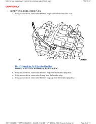
31. REMOVE THRUST NEEDLE ROLLER BEARING<br />
a. Remove the thrust needle roller bearing from the underdrive planetary gear assembly.<br />
Fig. 303: Identifying Thrust Needle Roller Bearing, Differential Gear Assembly And Forward Clutch<br />
Assembly<br />
Courtesy of TOYOTA MOTOR SALES, U.S.A., INC.<br />
32. REMOVE THRUST BEARING UNDERDRIVE RACE NO. 2<br />
a. Remove the thrust bearing underdrive race No.2 from the underdrive planetary gear assembly.<br />
<strong>AUTOMATIC</strong> TRANSMISSION - U151E -2006 Toyota Avalon Limited<br />
7/27/2012<br />
Page 34 of 203
http://www.ondemand5.com/mric/common/asp/printart.aspx<br />
Fig. 304: Identifying Thrust Bearing Underdrive Race No. 2, Differential Gear Assembly And Forward<br />
Clutch Assembly<br />
Courtesy of TOYOTA MOTOR SALES, U.S.A., INC.<br />
33. REMOVE DIFFERENTIAL GEAR ASSEMBLY<br />
a. Remove the differential gear assembly from the transaxle case.<br />
<strong>AUTOMATIC</strong> TRANSMISSION - U151E -2006 Toyota Avalon Limited<br />
7/27/2012<br />
Page 35 of 203
http://www.ondemand5.com/mric/common/asp/printart.aspx<br />
Fig. 305: View Of Differential Gear Assembly<br />
Courtesy of TOYOTA MOTOR SALES, U.S.A., INC.<br />
34. REMOVE OVERDRIVE BRAKE GASKET<br />
a. Remove the 2 overdrive brake gaskets from the transaxle case.<br />
Fig. 306: Identifying 2 O/D Brake Gaskets<br />
Courtesy of TOYOTA MOTOR SALES, U.S.A., INC.<br />
35. REMOVE FORWARD CLUTCH ASSEMBLY<br />
a. Remove the forward clutch assembly from the transaxle case.<br />
<strong>AUTOMATIC</strong> TRANSMISSION - U151E -2006 Toyota Avalon Limited<br />
7/27/2012<br />
Page 36 of 203
http://www.ondemand5.com/mric/common/asp/printart.aspx<br />
Fig. 307: View Of Forward Clutch Assembly<br />
Courtesy of TOYOTA MOTOR SALES, U.S.A., INC.<br />
b. Remove the thrust needle roller bearing from the forward clutch.<br />
<strong>AUTOMATIC</strong> TRANSMISSION - U151E -2006 Toyota Avalon Limited<br />
7/27/2012<br />
Page 37 of 203
http://www.ondemand5.com/mric/common/asp/printart.aspx<br />
Fig. 308: Removing Thrust Needle Roller Bearing<br />
Courtesy of TOYOTA MOTOR SALES, U.S.A., INC.<br />
36. REMOVE MULTIPLE DISC CLUTCH HUB<br />
a. Remove the thrust needle roller bearing, multiple disc clutch hub, thrust needle roller bearing and thrust bearing<br />
race No.1 from the transaxle case.<br />
37. INSPECT MULTIPLE DISC CLUTCH CLUTCH HUB<br />
HINT:<br />
(See INSPECTION)<br />
<strong>AUTOMATIC</strong> TRANSMISSION - U151E -2006 Toyota Avalon Limited<br />
7/27/2012<br />
Page 38 of 203
http://www.ondemand5.com/mric/common/asp/printart.aspx<br />
Fig. 309: Removing Multiple Disc Clutch Hub<br />
Courtesy of TOYOTA MOTOR SALES, U.S.A., INC.<br />
38. REMOVE UNDERDRIVE PLANETARY GEAR ASSEMBLY<br />
a. Remove the bolt and pawl shaft clamp.<br />
<strong>AUTOMATIC</strong> TRANSMISSION - U151E -2006 Toyota Avalon Limited<br />
7/27/2012<br />
Page 39 of 203
http://www.ondemand5.com/mric/common/asp/printart.aspx<br />
Fig. 310: View Of Pawl Shaft Clamp<br />
Courtesy of TOYOTA MOTOR SALES, U.S.A., INC.<br />
b. Remove the parking lock pawl shaft.<br />
Fig. 311: Removing Parking Lock Pawl Shaft<br />
Courtesy of TOYOTA MOTOR SALES, U.S.A., INC.<br />
c. Push the parking lock pawl.<br />
HINT:<br />
Failure to do so will cause interference when the underdrive planetary gear is removed.<br />
<strong>AUTOMATIC</strong> TRANSMISSION - U151E -2006 Toyota Avalon Limited<br />
7/27/2012<br />
Page 40 of 203
http://www.ondemand5.com/mric/common/asp/printart.aspx<br />
Fig. 312: Pushing Parking Lock Pawl<br />
Courtesy of TOYOTA MOTOR SALES, U.S.A., INC.<br />
d. Remove the underdrive planetary gear assembly from the transaxle case.<br />
NOTE: Be careful so that the underdrive planetary gear assembly will not fall out.<br />
<strong>AUTOMATIC</strong> TRANSMISSION - U151E -2006 Toyota Avalon Limited<br />
7/27/2012<br />
Page 41 of 203
http://www.ondemand5.com/mric/common/asp/printart.aspx<br />
Fig. 313: Identifying Underdrive Planetary Gear Assembly<br />
Courtesy of TOYOTA MOTOR SALES, U.S.A., INC.<br />
39. REMOVE PARKING LOCK PAWL<br />
a. Remove the spring, pawl pin and parking lock pawl.<br />
<strong>AUTOMATIC</strong> TRANSMISSION - U151E -2006 Toyota Avalon Limited<br />
7/27/2012<br />
Page 42 of 203
http://www.ondemand5.com/mric/common/asp/printart.aspx<br />
Fig. 314: Identifying Parking Lock Pawl, Shaft And Spring To Transaxle Case<br />
Courtesy of TOYOTA MOTOR SALES, U.S.A., INC.<br />
40. REMOVE UNDERDRIVE CLUTCH ASSEMBLY<br />
a. Remove the underdrive clutch assembly, thrust bearing and bearing race from the transaxle case.<br />
Fig. 315: Removing Thrust Bearing And Bearing Race<br />
Courtesy of TOYOTA MOTOR SALES, U.S.A., INC.<br />
41. REMOVE UNDERDRIVE 1-WAY CLUTCH ASSEMBLY<br />
a. Using a screwdriver, remove the snap ring from the transaxle case.<br />
NOTE: Do not apply excessive force when removing the snap ring.<br />
<strong>AUTOMATIC</strong> TRANSMISSION - U151E -2006 Toyota Avalon Limited<br />
7/27/2012<br />
Page 43 of 203
http://www.ondemand5.com/mric/common/asp/printart.aspx<br />
Fig. 316: Removing/Installing Snap Ring<br />
Courtesy of TOYOTA MOTOR SALES, U.S.A., INC.<br />
b. Remove the underdrive 1-way clutch from the transaxle case.<br />
<strong>AUTOMATIC</strong> TRANSMISSION - U151E -2006 Toyota Avalon Limited<br />
7/27/2012<br />
Page 44 of 203
http://www.ondemand5.com/mric/common/asp/printart.aspx<br />
Fig. 317: Removing Underdrive 1-Way Clutch<br />
Courtesy of TOYOTA MOTOR SALES, U.S.A., INC.<br />
c. Remove the outer race retainer from the 1-way clutch.<br />
Fig. 318: View Of 1-Way Clutch Outer Race Retainer<br />
Courtesy of TOYOTA MOTOR SALES, U.S.A., INC.<br />
42. REMOVE UNDERDRIVE CLUTCH DISC NO. 2<br />
a. Using a screwdriver, remove the snap ring.<br />
NOTE: Do not apply excessive force when removing the snap ring.<br />
<strong>AUTOMATIC</strong> TRANSMISSION - U151E -2006 Toyota Avalon Limited<br />
7/27/2012<br />
Page 45 of 203
http://www.ondemand5.com/mric/common/asp/printart.aspx<br />
Fig. 319: Removing Snap Ring<br />
Courtesy of TOYOTA MOTOR SALES, U.S.A., INC.<br />
b. Remove the flange, 4 discs and 4 plates from the transaxle case.<br />
43. INSPECT UNDERDRIVE CLUTCH DISC NO. 2<br />
HINT:<br />
(See INSPECTION)<br />
<strong>AUTOMATIC</strong> TRANSMISSION - U151E -2006 Toyota Avalon Limited<br />
7/27/2012<br />
Page 46 of 203
http://www.ondemand5.com/mric/common/asp/printart.aspx<br />
Fig. 320: Removing Flange<br />
Courtesy of TOYOTA MOTOR SALES, U.S.A., INC.<br />
44. REMOVE <strong>TRANSAXLE</strong> REAR COVER SUB-ASSEMBLY<br />
a. Remove the 11 bolts.<br />
b. Tap on the circumference of the rear cover with a plastic hammer to remove the transaxle rear cover from the<br />
transaxle case.<br />
<strong>AUTOMATIC</strong> TRANSMISSION - U151E -2006 Toyota Avalon Limited<br />
7/27/2012<br />
Page 47 of 203
http://www.ondemand5.com/mric/common/asp/printart.aspx<br />
Fig. 321: Removing 11 Bolts<br />
Courtesy of TOYOTA MOTOR SALES, U.S.A., INC.<br />
45. REMOVE <strong>TRANSAXLE</strong> CASE NO. 1 PLUG<br />
a. Remove the 4 transaxle case No.1 plugs from the transaxle rear cover.<br />
b. Remove the 4 O-rings from the 4 transaxle case No.1 plugs.<br />
Fig. 322: Identifying Transaxle Case No. 1 Plugs At Transaxle Rear Cover<br />
Courtesy of TOYOTA MOTOR SALES, U.S.A., INC.<br />
46. REMOVE REAR CLUTCH OIL SEAL RING OUTER<br />
a. Remove the 3 rear clutch oil seal rings from the transaxle rear cover.<br />
<strong>AUTOMATIC</strong> TRANSMISSION - U151E -2006 Toyota Avalon Limited<br />
7/27/2012<br />
Page 48 of 203
http://www.ondemand5.com/mric/common/asp/printart.aspx<br />
Fig. 323: Identifying 3 Rear Clutch Oil Seal Rings At Transaxle Rear Cover<br />
Courtesy of TOYOTA MOTOR SALES, U.S.A., INC.<br />
47. REMOVE NEEDLE-ROLLER BEARING<br />
a. Using SST, remove the needle-roller bearing from the transaxle rear cover.<br />
SST 09387-00041 (09387-01021, 09387-01030, 09387-01040)<br />
<strong>AUTOMATIC</strong> TRANSMISSION - U151E -2006 Toyota Avalon Limited<br />
7/27/2012<br />
Page 49 of 203
http://www.ondemand5.com/mric/common/asp/printart.aspx<br />
Fig. 324: Removing Needle-Roller Bearing<br />
Courtesy of TOYOTA MOTOR SALES, U.S.A., INC.<br />
48. REMOVE GOVERNOR APPLY GASKET NO. 1<br />
a. Using a screwdriver, remove the 3 apply gaskets.<br />
<strong>AUTOMATIC</strong> TRANSMISSION - U151E -2006 Toyota Avalon Limited<br />
7/27/2012<br />
Page 50 of 203
http://www.ondemand5.com/mric/common/asp/printart.aspx<br />
Fig. 325: Identifying Governor Apply Gaskets<br />
Courtesy of TOYOTA MOTOR SALES, U.S.A., INC.<br />
49. REMOVE BRAKE APPLY TUBE<br />
a. Remove the bolt, clamp and brake apply tube.<br />
b. Remove the clutch apply tube.<br />
c. Remove the brake apply tube from the clamp.<br />
NOTE: Do not bend the tubes.<br />
Fig. 326: Identifying Brake Apply And Clutch Apply Tubes<br />
Courtesy of TOYOTA MOTOR SALES, U.S.A., INC.<br />
50. REMOVE DIRECT CLUTCH ASSEMBLY<br />
a. Remove the thrust bearing and the direct clutch assembly from the transaxle case.<br />
<strong>AUTOMATIC</strong> TRANSMISSION - U151E -2006 Toyota Avalon Limited<br />
7/27/2012<br />
Page 51 of 203
http://www.ondemand5.com/mric/common/asp/printart.aspx<br />
Fig. 327: Identifying Thrust Bearing And Direct Clutch Assembly<br />
Courtesy of TOYOTA MOTOR SALES, U.S.A., INC.<br />
51. REMOVE OVERDRIVE DIRECT CLUTCH HUB SUB-ASSEMBLY<br />
a. Remove the thrust bearing race, thrust bearing and overdrive direct clutch hub from the planetary gear assembly.<br />
52. INSPECT OVERDRIVE DIRECT CLUTCH DRUM SUB-ASSEMBLY<br />
HINT:<br />
(See INSPECTION)<br />
<strong>AUTOMATIC</strong> TRANSMISSION - U151E -2006 Toyota Avalon Limited<br />
7/27/2012<br />
Page 52 of 203
http://www.ondemand5.com/mric/common/asp/printart.aspx<br />
Fig. 328: Removing Overdrive Direct Clutch Hub Sub-Assembly<br />
Courtesy of TOYOTA MOTOR SALES, U.S.A., INC.<br />
53. REMOVE REAR PLANETARY SUN GEAR ASSEMBLY<br />
a. Remove the rear planetary sun gear assembly from the transaxle case.<br />
<strong>AUTOMATIC</strong> TRANSMISSION - U151E -2006 Toyota Avalon Limited<br />
7/27/2012<br />
Page 53 of 203
http://www.ondemand5.com/mric/common/asp/printart.aspx<br />
Fig. 329: Identifying Rear Planetary Sun Gear Assembly<br />
Courtesy of TOYOTA MOTOR SALES, U.S.A., INC.<br />
b. Remove the thrust needle roller bearing and thrust bearing race from the rear planetary sun gear assembly.<br />
Fig. 330: Removing Thrust Needle Roller Bearing And Thrust Bearing Race<br />
Courtesy of TOYOTA MOTOR SALES, U.S.A., INC.<br />
c. Remove the planetary carrier thrust washer No.2 from the rear planetary sun gear assembly.<br />
<strong>AUTOMATIC</strong> TRANSMISSION - U151E -2006 Toyota Avalon Limited<br />
7/27/2012<br />
Page 54 of 203
http://www.ondemand5.com/mric/common/asp/printart.aspx<br />
Fig. 331: View Of Planetary Carrier Thrust Washer No. 2 And Rear Planetary Sun Gear<br />
Courtesy of TOYOTA MOTOR SALES, U.S.A., INC.<br />
54. REMOVE 1-WAY CLUTCH ASSEMBLY<br />
a. Remove the 1-way clutch assembly and the thrust needle roller bearing from the transaxle case.<br />
Fig. 332: Removing 1-Way Clutch Assembly And Thrust Needle Roller Bearing<br />
<strong>AUTOMATIC</strong> TRANSMISSION - U151E -2006 Toyota Avalon Limited<br />
7/27/2012<br />
Page 55 of 203
http://www.ondemand5.com/mric/common/asp/printart.aspx<br />
Courtesy of TOYOTA MOTOR SALES, U.S.A., INC.<br />
b. Remove the 1-way clutch inner race from the 1-way clutch assembly.<br />
Fig. 333: Identifying 1-Way Clutch Inner Race And 1-Way Clutch Assembly<br />
Courtesy of TOYOTA MOTOR SALES, U.S.A., INC.<br />
55. REMOVE 1-WAY CLUTCH SLEEVE OUTER<br />
a. Remove the 1-way clutch sleeve outer from the transaxle case.<br />
<strong>AUTOMATIC</strong> TRANSMISSION - U151E -2006 Toyota Avalon Limited<br />
7/27/2012<br />
Page 56 of 203
http://www.ondemand5.com/mric/common/asp/printart.aspx<br />
Fig. 334: Removing 1-Way Clutch Sleeve Outer<br />
Courtesy of TOYOTA MOTOR SALES, U.S.A., INC.<br />
56. REMOVE PLANETARY CARRIER THRUST WASHER NO. 1<br />
a. Remove the planetary carrier thrust washer No.1 from the planetary gear assembly.<br />
<strong>AUTOMATIC</strong> TRANSMISSION - U151E -2006 Toyota Avalon Limited<br />
7/27/2012<br />
Page 57 of 203
http://www.ondemand5.com/mric/common/asp/printart.aspx<br />
Fig. 335: Identifying Planetary Carrier Thrust Washer No 1<br />
Courtesy of TOYOTA MOTOR SALES, U.S.A., INC.<br />
57. REMOVE 2ND BRAKE CLUTCH DISC<br />
a. Using a screwdriver, remove the snap ring.<br />
Fig. 336: Removing Snap Ring<br />
Courtesy of TOYOTA MOTOR SALES, U.S.A., INC.<br />
b. Remove the flange, 4 discs and 4 plates from the transaxle case.<br />
58. INSPECT 2ND BRAKE CLUTCH DISC<br />
HINT:<br />
(See INSPECTION)<br />
59. REMOVE 2ND BRAKE PISTON ASSEMBLY<br />
a. Using a screwdriver, remove the snap ring.<br />
<strong>AUTOMATIC</strong> TRANSMISSION - U151E -2006 Toyota Avalon Limited<br />
7/27/2012<br />
Page 58 of 203
http://www.ondemand5.com/mric/common/asp/printart.aspx<br />
Fig. 337: Removing/Installing Snap Ring<br />
Courtesy of TOYOTA MOTOR SALES, U.S.A., INC.<br />
b. Remove the 2ND brake piston assembly from the transaxle case.<br />
<strong>AUTOMATIC</strong> TRANSMISSION - U151E -2006 Toyota Avalon Limited<br />
7/27/2012<br />
Page 59 of 203
http://www.ondemand5.com/mric/common/asp/printart.aspx<br />
Fig. 338: Removing 2Nd Brake Piston Assembly<br />
Courtesy of TOYOTA MOTOR SALES, U.S.A., INC.<br />
60. REMOVE REAR PLANETARY GEAR ASSEMBLY<br />
a. Using a screwdriver, remove the snap ring.<br />
Fig. 339: Removing/Installing Snap Ring<br />
Courtesy of TOYOTA MOTOR SALES, U.S.A., INC.<br />
b. Remove the rear planetary gear assembly from the transaxle case.<br />
<strong>AUTOMATIC</strong> TRANSMISSION - U151E -2006 Toyota Avalon Limited<br />
7/27/2012<br />
Page 60 of 203
http://www.ondemand5.com/mric/common/asp/printart.aspx<br />
Fig. 340: Identifying Rear Planetary Gear Assembly<br />
Courtesy of TOYOTA MOTOR SALES, U.S.A., INC.<br />
61. REMOVE INPUT SUN GEAR<br />
a. Remove the 2 thrust needle roller bearings, thrust bearing race No.2 and the input sun gear from the transaxle case.<br />
Fig. 341: Removing Input Sun Gear<br />
<strong>AUTOMATIC</strong> TRANSMISSION - U151E -2006 Toyota Avalon Limited<br />
7/27/2012<br />
Page 61 of 203
http://www.ondemand5.com/mric/common/asp/printart.aspx<br />
Courtesy of TOYOTA MOTOR SALES, U.S.A., INC.<br />
62. REMOVE 1ST AND REVERSE BRAKE CLUTCH DISC<br />
a. Remove the flange, 6 discs and 6 plates from the transaxle case.<br />
63. INSPECT 1ST AND REVERSE BRAKE CLUTCH DISC<br />
HINT:<br />
(See INSPECTION)<br />
Fig. 342: Removing Flange, 6 Discs And 6 Plates From Transaxle Case<br />
Courtesy of TOYOTA MOTOR SALES, U.S.A., INC.<br />
64. REMOVE FRONT PLANETARY GEAR ASSEMBLY<br />
a. Using a chisel and hammer, unstake the lock washer.<br />
7/27/2012<br />
NOTE: Push down all claws of the washer. Otherwise the SST cannot be fully pressed<br />
against the nut, and cannot loosen the nut.<br />
<strong>AUTOMATIC</strong> TRANSMISSION - U151E -2006 Toyota Avalon Limited<br />
Page 62 of 203
http://www.ondemand5.com/mric/common/asp/printart.aspx<br />
Fig. 343: Unstaking Lock Washer<br />
Courtesy of TOYOTA MOTOR SALES, U.S.A., INC.<br />
b. Using SST, remove the nut.<br />
SST 09387-00030, 09387-00080<br />
<strong>AUTOMATIC</strong> TRANSMISSION - U151E -2006 Toyota Avalon Limited<br />
7/27/2012<br />
Page 63 of 203
http://www.ondemand5.com/mric/common/asp/printart.aspx<br />
Fig. 344: Removing/Installing Front Planetary Gear Nut<br />
Courtesy of TOYOTA MOTOR SALES, U.S.A., INC.<br />
c. Using SST and a press, remove the front planetary gear assembly from the counter drive gear.<br />
SST 09950-60010 (09951-00450), 09950-70010 (09951-07100)<br />
Fig. 345: Removing Front Planetary Gear Assembly From Counter Drive Gear<br />
<strong>AUTOMATIC</strong> TRANSMISSION - U151E -2006 Toyota Avalon Limited<br />
7/27/2012<br />
Page 64 of 203
http://www.ondemand5.com/mric/common/asp/printart.aspx<br />
Courtesy of TOYOTA MOTOR SALES, U.S.A., INC.<br />
d. Remove the front planetary gear assembly from the brake hub.<br />
Fig. 346: View Of Front Planetary Gear Assembly And Brake Hub<br />
Courtesy of TOYOTA MOTOR SALES, U.S.A., INC.<br />
65. REMOVE FRONT PLANETARY RING GEAR<br />
a. Using a screwdriver, remove the snap ring and front planetary ring gear from the brake hub.<br />
<strong>AUTOMATIC</strong> TRANSMISSION - U151E -2006 Toyota Avalon Limited<br />
7/27/2012<br />
Page 65 of 203
http://www.ondemand5.com/mric/common/asp/printart.aspx<br />
Fig. 347: View Of Front Planetary Ring Gear, Snap Ring And Brake Hub<br />
Courtesy of TOYOTA MOTOR SALES, U.S.A., INC.<br />
66. REMOVE 1ST AND REVERSE BRAKE RETURN SPRING SUB-ASSEMBLY<br />
a. Place SST on the return spring, and compress the return spring with a press.<br />
SST 09387-00070<br />
b. Using a snap ring expander, remove the snap ring.<br />
7/27/2012<br />
NOTE: Stop the press when the spring seat is lowered 1 to 2 mm (0.039 to 0.078 in.) from<br />
the snap ring groove, to prevent the spring seat from being deformed.<br />
Do not expand the snap ring excessively.<br />
<strong>AUTOMATIC</strong> TRANSMISSION - U151E -2006 Toyota Avalon Limited<br />
Page 66 of 203
http://www.ondemand5.com/mric/common/asp/printart.aspx<br />
67. INSPECT 1ST AND REVERSE BRAKE RETURN SPRING SUB-ASSEMBLY<br />
HINT:<br />
(See INSPECTION)<br />
Fig. 348: Compressing Return Spring Using SST<br />
Courtesy of TOYOTA MOTOR SALES, U.S.A., INC.<br />
7/27/2012<br />
68. REMOVE 1ST AND REVERSE BRAKE PISTON<br />
a. Apply compressed air (392 kPa, 4.0 kgf/cm2 , 57 psi) to the transaxle case to remove the 1st and reverse brake<br />
piston.<br />
NOTE: Applying compressed air may cause the piston to jump-out. When removing the<br />
piston, hold it using a waste cloth.<br />
Take care not to splash ATF when applying compressed air.<br />
<strong>AUTOMATIC</strong> TRANSMISSION - U151E -2006 Toyota Avalon Limited<br />
Page 67 of 203
http://www.ondemand5.com/mric/common/asp/printart.aspx<br />
Fig. 349: Removing 1st And Reverse Brake Piston<br />
Courtesy of TOYOTA MOTOR SALES, U.S.A., INC.<br />
b. Remove the 2 O-rings from the 1st and reverse brake piston.<br />
Fig. 350: Locating 2 O-Rings<br />
Courtesy of TOYOTA MOTOR SALES, U.S.A., INC.<br />
<strong>AUTOMATIC</strong> TRANSMISSION - U151E -2006 Toyota Avalon Limited<br />
7/27/2012<br />
Page 68 of 203
http://www.ondemand5.com/mric/common/asp/printart.aspx<br />
69. REMOVE COUNTER DRIVE GEAR<br />
a. Using SST and a press, remove the counter drive gear from the transaxle case.<br />
SST 09950-60010 (09951-00590), 09950-70010 (09951-07100)<br />
Fig. 351: Removing Counter Drive Gear<br />
Courtesy of TOYOTA MOTOR SALES, U.S.A., INC.<br />
7/27/2012<br />
b. As shown in Fig. 352, tighten the 2 bolts evenly and make clearance of approx. 20.0 mm (0.787 in.) between the<br />
counter drive gear and the inner race.<br />
<strong>AUTOMATIC</strong> TRANSMISSION - U151E -2006 Toyota Avalon Limited<br />
Page 69 of 203
http://www.ondemand5.com/mric/common/asp/printart.aspx<br />
Fig. 352: Tightening Bolts Evenly And Checking Clearance Between Counter Drive Gear And Inner Race<br />
Courtesy of TOYOTA MOTOR SALES, U.S.A., INC.<br />
c. Using SST, remove the tapered roller bearing.<br />
SST 09950-60010 (09951-00590), 09950-00020, 09950-00030, 09950-40011 (09957-04010)<br />
<strong>AUTOMATIC</strong> TRANSMISSION - U151E -2006 Toyota Avalon Limited<br />
7/27/2012<br />
Page 70 of 203
http://www.ondemand5.com/mric/common/asp/printart.aspx<br />
Fig. 353: Removing Tapered Roller Bearing Using SST<br />
Courtesy of TOYOTA MOTOR SALES, U.S.A., INC.<br />
70. REMOVE TRANSFER DRIVEN PINION FRONT BEARING<br />
a. Using a snap ring expander, remove the snap ring.<br />
Fig. 354: Removing/Installing Snap Ring<br />
Courtesy of TOYOTA MOTOR SALES, U.S.A., INC.<br />
b. Using SST and a press, remove the bearing outer race.<br />
SST 09950-60020 (09951-00910)<br />
71. REMOVE BREATHER PLUG NO. 2 (ATM)<br />
<strong>AUTOMATIC</strong> TRANSMISSION - U151E -2006 Toyota Avalon Limited<br />
7/27/2012<br />
Page 71 of 203
http://www.ondemand5.com/mric/common/asp/printart.aspx<br />
Fig. 355: Removing Bearing Outer Race<br />
Courtesy of TOYOTA MOTOR SALES, U.S.A., INC.<br />
72. REMOVE UNDERDRIVE BRAKE RETURN SPRING SUB-ASSEMBLY<br />
a. Place SST on the return spring, and compress the return spring with a press.<br />
SST 09387-00020<br />
b. Using a snap ring expander, remove the snap ring.<br />
7/27/2012<br />
NOTE: Stop the press when the spring seat is lowered 1 to 2 mm (0.039 to 0.078 in.) from<br />
the snap ring groove, to prevent the spring seat from being deformed.<br />
Do not expand the snap ring excessively.<br />
<strong>AUTOMATIC</strong> TRANSMISSION - U151E -2006 Toyota Avalon Limited<br />
Page 72 of 203
http://www.ondemand5.com/mric/common/asp/printart.aspx<br />
73. INSPECT UNDERDRIVE BRAKE RETURN SPRING SUB-ASSEMBLY<br />
HINT:<br />
(See INSPECTION)<br />
Fig. 356: View Of SST And Snap Ring<br />
Courtesy of TOYOTA MOTOR SALES, U.S.A., INC.<br />
7/27/2012<br />
74. REMOVE UNDERDRIVE BRAKE PISTON<br />
a. Apply compressed air (392 kPa, 4.0 kgf/cm2 , 57 psi) to the transaxle case to remove the underdrive brake piston.<br />
<strong>AUTOMATIC</strong> TRANSMISSION - U151E -2006 Toyota Avalon Limited<br />
Page 73 of 203
http://www.ondemand5.com/mric/common/asp/printart.aspx<br />
Fig. 357: Removing Underdrive Brake Piston<br />
Courtesy of TOYOTA MOTOR SALES, U.S.A., INC.<br />
b. Remove the 2 O-rings from the underdrive brake piston.<br />
<strong>AUTOMATIC</strong> TRANSMISSION - U151E -2006 Toyota Avalon Limited<br />
7/27/2012<br />
Page 74 of 203
http://www.ondemand5.com/mric/common/asp/printart.aspx<br />
Fig. 358: Locating Brake Piston O-Rings<br />
Courtesy of TOYOTA MOTOR SALES, U.S.A., INC.<br />
75. REMOVE NEEDLE ROLLER BEARING<br />
a. Using SST, remove the needleroller bearing from the transaxle case.<br />
SST 09387-00041 (09387-01010, 09387-01030, 09387-01040)<br />
<strong>AUTOMATIC</strong> TRANSMISSION - U151E -2006 Toyota Avalon Limited<br />
7/27/2012<br />
Page 75 of 203
http://www.ondemand5.com/mric/common/asp/printart.aspx<br />
Fig. 359: Removing Needle Roller Bearing<br />
Courtesy of TOYOTA MOTOR SALES, U.S.A., INC.<br />
76. REMOVE UNDERDRIVE CLUTCH DRUM OIL SEAL RING<br />
a. Remove the 2 oil seal rings from the transaxle case.<br />
<strong>AUTOMATIC</strong> TRANSMISSION - U151E -2006 Toyota Avalon Limited<br />
7/27/2012<br />
Page 76 of 203
http://www.ondemand5.com/mric/common/asp/printart.aspx<br />
Fig. 360: Removing Underdrive Clutch Drum Oil Seal Ring<br />
Courtesy of TOYOTA MOTOR SALES, U.S.A., INC.<br />
77. REMOVE <strong>TRANSAXLE</strong> CASE NO. 1 PLUG<br />
a. Remove the 2 transaxle case No.1 plugs.<br />
b. Remove the 2 O-rings from the 2 transaxle case No.1 plugs.<br />
Fig. 361: Identifying Transaxle Case No 1 Plugs<br />
<strong>AUTOMATIC</strong> TRANSMISSION - U151E -2006 Toyota Avalon Limited<br />
7/27/2012<br />
Page 77 of 203
http://www.ondemand5.com/mric/common/asp/printart.aspx<br />
Courtesy of TOYOTA MOTOR SALES, U.S.A., INC.<br />
78. REMOVE UNDERDRIVE CYLINDRICAL ROLLER BEARING<br />
a. Using SST, remove the underdrive cylindrical roller bearing from the transaxle case.<br />
SST 09514-35011<br />
Fig. 362: Removing Underdrive Cylindrical Roller Bearing<br />
Courtesy of TOYOTA MOTOR SALES, U.S.A., INC.<br />
79. REMOVE UNDERDRIVE OUTPUT SHAFT OIL SEAL RING<br />
a. Remove the oil seal ring from the transaxle housing.<br />
<strong>AUTOMATIC</strong> TRANSMISSION - U151E -2006 Toyota Avalon Limited<br />
7/27/2012<br />
Page 78 of 203
http://www.ondemand5.com/mric/common/asp/printart.aspx<br />
Fig. 363: Removing Underdrive Output Shaft Oil Seal Ring<br />
Courtesy of TOYOTA MOTOR SALES, U.S.A., INC.<br />
80. REMOVE DIFFERENTIAL GEAR LUBE APPLY TUBE<br />
a. Remove the bolt, transaxle apply tube clamp and differential gear lube apply tube from the transaxle housing.<br />
NOTE: Do not bend the tubes.<br />
<strong>AUTOMATIC</strong> TRANSMISSION - U151E -2006 Toyota Avalon Limited<br />
7/27/2012<br />
Page 79 of 203
http://www.ondemand5.com/mric/common/asp/printart.aspx<br />
INSPECTION<br />
Fig. 364: Removing Transaxle Apply Tube Clamp And Differential Gear Lube Apply Tube<br />
Courtesy of TOYOTA MOTOR SALES, U.S.A., INC.<br />
1. INSPECT MULTIPLE DISC CLUTCH HUB<br />
a. Using a dial indicator, measure the inside diameter of the forward clutch hub bushing<br />
<strong>AUTOMATIC</strong> TRANSMISSION - U151E -2006 Toyota Avalon Limited<br />
7/27/2012<br />
Page 80 of 203
http://www.ondemand5.com/mric/common/asp/printart.aspx<br />
Fig. 365: Measuring Inside Diameter Of Forward Clutch Hub Bushing<br />
Courtesy of TOYOTA MOTOR SALES, U.S.A., INC.<br />
Standard inside diameter:<br />
23.025 to 23.046 mm (0.9065 to 0.9073 in.)<br />
Maximum inside diameter:<br />
23.09 mm (0.9091 in.)<br />
NOTE: Check the contact surface of the bushing in the direct clutch shaft. If any scratch<br />
or discoloration is found, replace the direct clutch sub-assembly with a new one.<br />
If the inside diameter is greater than the maximum, replace the forward clutch hub with a new one.<br />
2. INSPECT UNDERDRIVE CLUTCH DISC NO. 2<br />
a. Check if the sliding surfaces of the disc, plate and flange are worn or burnt.<br />
If necessary, replace them.<br />
NOTE: If the lining of the disc comes off or discolors, or if a part of the groove is worn,<br />
replace all discs.<br />
Before installing new discs, immerse them in ATF for at least 15 minutes.<br />
Fig. 366: Identifying Underdrive Clutch Disc No.2<br />
Courtesy of TOYOTA MOTOR SALES, U.S.A., INC.<br />
3. INSPECT OVERDRIVE DIRECT CLUTCH DRUM SUB-ASSEMBLY<br />
a. Using a dial indicator, measure the inside diameter of the forward clutch hub bushing.<br />
<strong>AUTOMATIC</strong> TRANSMISSION - U151E -2006 Toyota Avalon Limited<br />
7/27/2012<br />
Page 81 of 203
http://www.ondemand5.com/mric/common/asp/printart.aspx<br />
Fig. 367: Measuring Inside Diameter Of Forward Clutch Hub Bushing<br />
Courtesy of TOYOTA MOTOR SALES, U.S.A., INC.<br />
Standard inside diameter:<br />
23.025 to 23.046 mm (0.9065 to 0.9073 in.)<br />
Maximum inside diameter:<br />
23.09 mm (0.9091 in.)<br />
NOTE: Check the contact surface of the bushing in the direct clutch shaft. If any scratch<br />
or discoloration is found, replace the direct clutch sub-assembly with a new one.<br />
If the inside diameter is greater than the maximum, replace the forward clutch hub with a new one.<br />
4. INSPECT 2ND BRAKE CLUTCH DISC<br />
a. Check if the sliding surface of the disc, plate and flange are worn or burnt.<br />
If necessary, replace them.<br />
7/27/2012<br />
NOTE: If the lining of the disc comes off or discolors, or if a part of the groove is worn,<br />
replace all discs.<br />
Before installing new discs, immerse them in ATF for at least 15 minutes.<br />
<strong>AUTOMATIC</strong> TRANSMISSION - U151E -2006 Toyota Avalon Limited<br />
Page 82 of 203
http://www.ondemand5.com/mric/common/asp/printart.aspx<br />
5. INSPECT 1ST AND REVERSE BRAKE CLUTCH DISC<br />
a. Check if the sliding surface of the disc, plate and flange are worn or burnt.<br />
If necessary, replace them.<br />
Fig. 368: Identifying 2nd Brake Clutch Disc<br />
Courtesy of TOYOTA MOTOR SALES, U.S.A., INC.<br />
7/27/2012<br />
NOTE: If the lining of the disc comes off or discolors, or if a part of the groove is worn,<br />
replace all discs.<br />
Before installing new discs, immerse them in ATF for at least 15 minutes.<br />
<strong>AUTOMATIC</strong> TRANSMISSION - U151E -2006 Toyota Avalon Limited<br />
Page 83 of 203
http://www.ondemand5.com/mric/common/asp/printart.aspx<br />
6. INSPECT 1ST AND REVERSE BRAKE RETURN SPRING SUB-ASSEMBLY<br />
a. Using a vernier calipers, measure the free length of the spring together with the spring seat.<br />
Standard free length:<br />
17.61 mm (0.6933 in.)<br />
HINT:<br />
Fig. 369: View Of Clutch Disc<br />
Courtesy of TOYOTA MOTOR SALES, U.S.A., INC.<br />
If the result is not as specified, replace the spring.<br />
<strong>AUTOMATIC</strong> TRANSMISSION - U151E -2006 Toyota Avalon Limited<br />
7/27/2012<br />
Page 84 of 203
http://www.ondemand5.com/mric/common/asp/printart.aspx<br />
Fig. 370: Measuring Free Length Of Spring<br />
Courtesy of TOYOTA MOTOR SALES, U.S.A., INC.<br />
7. INSPECT UNDERDRIVE BRAKE RETURN SPRING SUB-ASSEMBLY<br />
a. Using a vernier calipers, measure the free length of the spring together with the spring seat.<br />
Standard free length:<br />
13.24 mm (0.5213 in.)<br />
HINT:<br />
If the result is not as specified, replace the spring.<br />
<strong>AUTOMATIC</strong> TRANSMISSION - U151E -2006 Toyota Avalon Limited<br />
7/27/2012<br />
Page 85 of 203
http://www.ondemand5.com/mric/common/asp/printart.aspx<br />
Fig. 371: Measuring Free Length Of Spring (Underdrive Brake Return Spring)<br />
Courtesy of TOYOTA MOTOR SALES, U.S.A., INC.<br />
8. INSPECT PACK CLEARANCE OF 1ST AND REVERSE BRAKE<br />
a. Using vernier calipers, measure the distance between the disc surface and the contact surface of the 2nd brake<br />
cylinder and transaxle case (Dimension A).<br />
b. Select an appropriate flange so that the pack clearance will meet the specified value.<br />
Pack clearance:<br />
1.16 to 1.35 mm (0.0457 to 0.0531 in.)<br />
<strong>AUTOMATIC</strong> TRANSMISSION - U151E -2006 Toyota Avalon Limited<br />
7/27/2012<br />
Page 86 of 203
http://www.ondemand5.com/mric/common/asp/printart.aspx<br />
Fig. 372: Measuring (Dimension A)<br />
Courtesy of TOYOTA MOTOR SALES, U.S.A., INC.<br />
HINT:<br />
Piston stroke = Dimension A - Flange thickness<br />
Flange thickness: mm (in.)<br />
FLANGE THICKNESS SPECIFICATIONS<br />
Mark Thickness<br />
1 1.8 (0.071)<br />
2 1.9 (0.075)<br />
3 2.0 (0.079)<br />
4 2.1 (0.083)<br />
5 2.2 (0.087)<br />
6 2.3 (0.091)<br />
7 2.4 (0.094)<br />
8 2.5 (0.098)<br />
c. Install the flange.<br />
9. INSPECT PACK CLEARANCE OF 2ND BRAKE<br />
a. Using a vernier calipers, measure the distance between the disc surface and snap ring surface (Dimension B).<br />
b. Select an appropriate flange so that the pack clearance will meet the specified value.<br />
Pack clearance:<br />
0.62 to 0.91 mm (0.0244 to 0.0358 in.)<br />
HINT:<br />
<strong>AUTOMATIC</strong> TRANSMISSION - U151E -2006 Toyota Avalon Limited<br />
7/27/2012<br />
Page 87 of 203
http://www.ondemand5.com/mric/common/asp/printart.aspx<br />
Piston stroke = Dimension B - Flange thickness - Snap ring thickness 1.6 mm (0.063 in.)<br />
Flange thickness: mm (in.)<br />
FLANGE THICKNESS SPECIFICATIONS<br />
Mark Thickness<br />
1 3.0 (0.118)<br />
2 3.1 (0.122)<br />
3 3.2 (0.126)<br />
4 3.3 (0.130)<br />
5 3.4 (0.134)<br />
6 3.5 (0.138)<br />
7 3.6 (0.142)<br />
8 -<br />
Fig. 373: Measuring Dimension B<br />
Courtesy of TOYOTA MOTOR SALES, U.S.A., INC.<br />
10. INSPECT PACK CLEARANCE OF UNDERDRIVE BRAKE<br />
a. Using a dial indicator, measure the underdrive brake pack clearance while applying and releasing compressed air<br />
(392 kPa, 4.0 kgf/cm 2 , 57 psi).<br />
Pack clearance:<br />
1.81 to 2.20 mm (0.0713 to 0.0866 in.)<br />
HINT:<br />
Select an appropriate flange from the table below so that it will meet the specified value.<br />
Flange thickness: mm (in.)<br />
<strong>AUTOMATIC</strong> TRANSMISSION - U151E -2006 Toyota Avalon Limited<br />
7/27/2012<br />
Page 88 of 203
http://www.ondemand5.com/mric/common/asp/printart.aspx<br />
FLANGE THICKNESS SPECIFICATIONS<br />
Mark Thickness<br />
1 3.0 (0.118)<br />
2 3.2 (0.126)<br />
3 3.4 (0.134)<br />
4 3.1 (0.122)<br />
5 3.3 (0.130)<br />
- -<br />
Fig. 374: Measuring Underdrive Brake Pack Clearance<br />
Courtesy of TOYOTA MOTOR SALES, U.S.A., INC.<br />
b. Temporarily remove the snap ring and attach it to the flange.<br />
c. Reinstall the snap ring.<br />
11. INSPECT UNDERDRIVE 1-WAY CLUTCH ASSEMBLY<br />
a. Install the underdrive clutch assembly to the 1-way clutch.<br />
b. Rotate the underdrive 1-way clutch assembly to check the rotating direction for the lock or free operation.<br />
HINT:<br />
If the result is not as specified, replace the underdrive 1-way clutch.<br />
<strong>AUTOMATIC</strong> TRANSMISSION - U151E -2006 Toyota Avalon Limited<br />
7/27/2012<br />
Page 89 of 203
http://www.ondemand5.com/mric/common/asp/printart.aspx<br />
Fig. 375: Checking Underdrive Clutch Assembly Rotation<br />
Courtesy of TOYOTA MOTOR SALES, U.S.A., INC.<br />
12. INSPECT INPUT SHAFT END PLAY<br />
a. Using a dial indicator, measure the input shaft end play.<br />
End play:<br />
0.262 to 1.244 mm (0.01 to 0.049 in.)<br />
HINT:<br />
If the result is not as specified, replace the input shaft or thrust needle roller bearing.<br />
<strong>AUTOMATIC</strong> TRANSMISSION - U151E -2006 Toyota Avalon Limited<br />
7/27/2012<br />
Page 90 of 203
http://www.ondemand5.com/mric/common/asp/printart.aspx<br />
REASSEMBLY<br />
Fig. 376: Inspecting Input Shaft End Play<br />
Courtesy of TOYOTA MOTOR SALES, U.S.A., INC.<br />
1. BEARING POSITION<br />
<strong>AUTOMATIC</strong> TRANSMISSION - U151E -2006 Toyota Avalon Limited<br />
7/27/2012<br />
Page 91 of 203
http://www.ondemand5.com/mric/common/asp/printart.aspx<br />
Fig. 377: Identifying Bearing Position<br />
Courtesy of TOYOTA MOTOR SALES, U.S.A., INC.<br />
BEARING SPECIFICATIONS<br />
Mark<br />
Front Race Diameter<br />
Inside/Outside mm(in.)<br />
Thrust Bearing Diameter<br />
Inside/Outside mm(in.)<br />
Rear Race Diameter<br />
Inside/Outside mm(in.)<br />
A - 57.2(2.252)/84.96(3.3449) 56.4(2.220)/83.0(3.268)<br />
B - 37.73(1.4854)/58.0(2.283) -<br />
C - 33.85(1.3327)/52.2(2.055) -<br />
D 24.94(0.982) 23.5(0.925)/44.0(1.732) -<br />
E - 36.3(1.429)/51.93(2.044) 34.5(1.358)/48.35(1.904)<br />
F 34.35(1.352)/56.57(2.227) 32.45(1.278)/56.48(2.223) -<br />
G 40.15(1.581)/59.25(2.333) 38.65(1.522)/59.79(2.354) 38.65(1.522)/59.25(2.332)<br />
H - 53.6(2.110)/69.6(2.740) -<br />
I 33.02(1.3)/45.8(1.803) 31.85(1.254)/57.3(2.256) -<br />
<strong>AUTOMATIC</strong> TRANSMISSION - U151E -2006 Toyota Avalon Limited<br />
7/27/2012<br />
Page 92 of 203
http://www.ondemand5.com/mric/common/asp/printart.aspx<br />
J - 24.79(0.976)/39.5(1.555) 23.6(0.929)/37.95(1.494)<br />
K - 56.3(2.216)/75.96(2.991) -<br />
2. INSTALL DIFFERENTIAL GEAR LUBE APPLY TUBE<br />
a. Install the differential gear lube apply tube and transaxle apply tube clamp with the bolt to the transaxle housing.<br />
Torque: 9.8 N*m (100 kgf*cm, 87 in.*lbf)<br />
NOTE: Make sure to insert the pipe to the stopper.<br />
Fig. 378: Installing Differential Gear Lube Apply Tube And Transaxle Apply Tube Clamp<br />
Courtesy of TOYOTA MOTOR SALES, U.S.A., INC.<br />
3. INSTALL <strong>TRANSAXLE</strong> CASE NO. 1 PLUG<br />
a. Install 2 new O-rings to the 2 transaxle case No.1 plugs.<br />
b. Install the 2 transaxle case No.1 plugs to the transaxle rear cover.<br />
<strong>AUTOMATIC</strong> TRANSMISSION - U151E -2006 Toyota Avalon Limited<br />
7/27/2012<br />
Page 93 of 203
http://www.ondemand5.com/mric/common/asp/printart.aspx<br />
Torque: 7.4 N*m (75 kgf*cm, 65 in.*lbf)<br />
Fig. 379: Identifying Transaxle Case No 1 Plugs<br />
Courtesy of TOYOTA MOTOR SALES, U.S.A., INC.<br />
4. INSTALL UNDERDRIVE OUTPUT SHAFT OIL SEAL RING<br />
a. Coat a new oil seal ring with ATF and install it to the transaxle housing.<br />
<strong>AUTOMATIC</strong> TRANSMISSION - U151E -2006 Toyota Avalon Limited<br />
7/27/2012<br />
Page 94 of 203
http://www.ondemand5.com/mric/common/asp/printart.aspx<br />
Fig. 380: Installing Underdrive Output Shaft Oil Seal Ring<br />
Courtesy of TOYOTA MOTOR SALES, U.S.A., INC.<br />
5. INSTALL UNDERDRIVE CYLINDRICAL ROLLER BEARING<br />
a. Coat the underdrive cylindrical roller bearing with ATF.<br />
b. Using SST and a press, install the underdrive cylindrical roller bearing.<br />
SST 09950-60020 (09951-00810), 09950-70010 (09951-07100)<br />
NOTE: Do not apply excessive pressure to the bearing.<br />
<strong>AUTOMATIC</strong> TRANSMISSION - U151E -2006 Toyota Avalon Limited<br />
7/27/2012<br />
Page 95 of 203
http://www.ondemand5.com/mric/common/asp/printart.aspx<br />
Fig. 381: Pressing In Underdrive Cylindrical Roller Bearing<br />
Courtesy of TOYOTA MOTOR SALES, U.S.A., INC.<br />
6. INSTALL UNDERDRIVE CLUTCH DRUM OIL SEAL RING<br />
a. Coat 2 new oil seal rings with ATF, and install them to the transaxle rear cover.<br />
NOTE: Do not expand the end gap of the oil seal ring too much.<br />
Fix the hooks firmly. Confirm that the oil seal ring rotates freely in its groove.<br />
<strong>AUTOMATIC</strong> TRANSMISSION - U151E -2006 Toyota Avalon Limited<br />
7/27/2012<br />
Page 96 of 203
http://www.ondemand5.com/mric/common/asp/printart.aspx<br />
Fig. 382: Installing Underdrive Clutch Drum Oil Seal Ring<br />
Courtesy of TOYOTA MOTOR SALES, U.S.A., INC.<br />
7. INSTALL NEEDLE ROLLER BEARING<br />
a. Wrap vinyl tape around the SST 4.0 mm (0.157 in.) from the bottom of the SST until the thickness of the tape is<br />
about 5.0 mm (0.197 in.).<br />
SST 09950-60010 (09951-00320), 09950-70010 (09951-07100)<br />
NOTE: Clean SST to remove deposited oil, before wrapping vinyl tape.<br />
b. Coat the needle roller bearing with ATF.<br />
<strong>AUTOMATIC</strong> TRANSMISSION - U151E -2006 Toyota Avalon Limited<br />
7/27/2012<br />
Page 97 of 203
http://www.ondemand5.com/mric/common/asp/printart.aspx<br />
Fig. 383: Wrapping Vinyl Tape Around SST<br />
Courtesy of TOYOTA MOTOR SALES, U.S.A., INC.<br />
c. Using SST and a press, install the needle-roller bearing to the transaxle case.<br />
SST 09950-60010 (09951-00320), 09950-70010 (09951-07100)<br />
NOTE: When the wrapped vinyl tape contacts the transaxle case, stop press-fitting.<br />
<strong>AUTOMATIC</strong> TRANSMISSION - U151E -2006 Toyota Avalon Limited<br />
7/27/2012<br />
Page 98 of 203
http://www.ondemand5.com/mric/common/asp/printart.aspx<br />
Fig. 384: Pressing In Needle-Roller Bearing To Transaxle Case<br />
Courtesy of TOYOTA MOTOR SALES, U.S.A., INC.<br />
8. INSTALL UNDERDRIVE BRAKE PISTON<br />
a. Coat 2 new O-rings with ATF, and install them to the underdrive brake piston.<br />
NOTE: Make sure that the O-rings are not twisted or pinched when they are<br />
installed.<br />
Apply sufficient ATF to the O-ring before installing.<br />
b. Coat the underdrive brake piston with ATF.<br />
<strong>AUTOMATIC</strong> TRANSMISSION - U151E -2006 Toyota Avalon Limited<br />
7/27/2012<br />
Page 99 of 203
http://www.ondemand5.com/mric/common/asp/printart.aspx<br />
Fig. 385: Locating O-Rings<br />
Courtesy of TOYOTA MOTOR SALES, U.S.A., INC.<br />
c. Install the underdrive brake piston to the transaxle case.<br />
NOTE: Be careful not to damage the O-ring.<br />
<strong>AUTOMATIC</strong> TRANSMISSION - U151E -2006 Toyota Avalon Limited<br />
7/27/2012<br />
Page 100 of 203
http://www.ondemand5.com/mric/common/asp/printart.aspx<br />
Fig. 386: Installing Underdrive Brake Piston<br />
Courtesy of TOYOTA MOTOR SALES, U.S.A., INC.<br />
9. INSTALL UNDERDRIVE BRAKE RETURN SPRING SUB-ASSEMBLY<br />
a. Place SST on the return spring and compress the return spring with a press.<br />
SST 09387-00020<br />
b. Using a snap ring expander, install the snap ring to the transaxle case.<br />
7/27/2012<br />
NOTE: Stop the press when the spring seat is lowered 1 to 2 mm (0.039 to 0.078 in.) from<br />
the snap ring groove, to prevent the spring seat from being deformed.<br />
Do not expand the snap ring excessively.<br />
Installing the spring sub-assembly, check that all of the springs are fit in the<br />
piston correctly.<br />
The snap ring should be fully engaged in the groove of the transaxle case.<br />
<strong>AUTOMATIC</strong> TRANSMISSION - U151E -2006 Toyota Avalon Limited<br />
Page 101 of 203
http://www.ondemand5.com/mric/common/asp/printart.aspx<br />
Fig. 387: View Of SST And Snap Ring<br />
Courtesy of TOYOTA MOTOR SALES, U.S.A., INC.<br />
10. INSTALL BREATHER PLUG NO. 2 (ATM)<br />
11. INSTALL COUNTER DRIVE GEAR BEARING<br />
a. Coat the counterdrive gear bearing with ATF.<br />
b. Using SST and a press, install the bearing outer race.<br />
SST 09950-60020 (09951-01030), 09950-70010 (09951-07150), 09649-17010<br />
NOTE: Do not apply excessive pressure to the bearing.<br />
Press-fit the bearing outer race until it contacts the transaxle case.<br />
<strong>AUTOMATIC</strong> TRANSMISSION - U151E -2006 Toyota Avalon Limited<br />
7/27/2012<br />
Page 102 of 203
http://www.ondemand5.com/mric/common/asp/printart.aspx<br />
Fig. 388: Installing Bearing Outer Race Using SST And Press<br />
Courtesy of TOYOTA MOTOR SALES, U.S.A., INC.<br />
c. Using a snap ring expander, install the snap ring.<br />
NOTE: The white mark side of the snap ring should face upward.<br />
<strong>AUTOMATIC</strong> TRANSMISSION - U151E -2006 Toyota Avalon Limited<br />
7/27/2012<br />
Page 103 of 203
http://www.ondemand5.com/mric/common/asp/printart.aspx<br />
Fig. 389: Removing/Installing Snap Ring<br />
Courtesy of TOYOTA MOTOR SALES, U.S.A., INC.<br />
12. INSTALL COUNTER DRIVE GEAR<br />
a. Coat the couterdrive gear with ATF.<br />
b. Using SST and a press, install the tapered roller bearing to the counter drive gear.<br />
SST 09950-70010 (09951-07150), 09649-17010<br />
NOTE: Do not apply excessive pressure to the bearing.<br />
Fig. 390: Installing Tapered Roller Bearing To Counter Drive Gear<br />
Courtesy of TOYOTA MOTOR SALES, U.S.A., INC.<br />
c. Using SST and a press, install the counter drive gear and bearing to the transaxle case.<br />
SST 09950-70010 (09951-07150), 09223-15030, 09527-17011, 09950-60020 (09951-00750)<br />
NOTE: Do not apply excessive pressure to the counter drive gear.<br />
<strong>AUTOMATIC</strong> TRANSMISSION - U151E -2006 Toyota Avalon Limited<br />
7/27/2012<br />
Page 104 of 203
http://www.ondemand5.com/mric/common/asp/printart.aspx<br />
Fig. 391: Installing Counter Drive Gear And Bearing To Transaxle Case Using SST And Press<br />
Courtesy of TOYOTA MOTOR SALES, U.S.A., INC.<br />
13. INSTALL 1ST AND REVERSE BRAKE PISTON<br />
a. Coat 2 new O-rings with ATF.<br />
b. Install the 2 O-rings to the 1st and reverse brake piston.<br />
NOTE: Make sure that the O-rings are not twisted or pinched when they are installed.<br />
Apply sufficient ATF to the O-ring prior to assembling.<br />
<strong>AUTOMATIC</strong> TRANSMISSION - U151E -2006 Toyota Avalon Limited<br />
7/27/2012<br />
Page 105 of 203
http://www.ondemand5.com/mric/common/asp/printart.aspx<br />
Fig. 392: Locating 2 O-Rings<br />
Courtesy of TOYOTA MOTOR SALES, U.S.A., INC.<br />
c. Coat the 1st and reverse brake piston with ATF, and install it to the transaxle case.<br />
NOTE: Be careful not to damage the O-ring.<br />
<strong>AUTOMATIC</strong> TRANSMISSION - U151E -2006 Toyota Avalon Limited<br />
7/27/2012<br />
Page 106 of 203
http://www.ondemand5.com/mric/common/asp/printart.aspx<br />
Fig. 393: Installing 1st And Reverse Brake Piston<br />
Courtesy of TOYOTA MOTOR SALES, U.S.A., INC.<br />
14. INSTALL 1ST AND REVERSE BRAKE RETURN SPRING SUB-ASSEMBLY<br />
a. Place SST on the return spring and compress the return spring with a press.<br />
SST 09387-00070<br />
b. Using a snap ring expander, install the snap ring to the transaxle case.<br />
Fig. 394: Compressing Return Spring Using SST<br />
Courtesy of TOYOTA MOTOR SALES, U.S.A., INC.<br />
NOTE: Stop the press when the spring seat is lowered to the place 1 to 2 mm (0.039<br />
to 0.078 in.) from the snap ring groove, preventing the spring seat from being<br />
deformed.<br />
Do not expand the snap ring excessively.<br />
Installing the spring sub-assembly, check that all of the springs are fit in the<br />
piston correctly.<br />
The snap ring should be fully engaged in the groove of the cylinder.<br />
Fix the snap ring to the inside of the claw of the spring seat firmly.<br />
15. INSTALL FRONT PLANETARY RING GEAR<br />
a. Using a screwdriver, install the front planetary ring gear and snap ring to the brake hub.<br />
7/27/2012<br />
NOTE: Confirm that the snap ring is engaged in the groove of the brake hub correctly.<br />
<strong>AUTOMATIC</strong> TRANSMISSION - U151E -2006 Toyota Avalon Limited<br />
Page 107 of 203
http://www.ondemand5.com/mric/common/asp/printart.aspx<br />
Fig. 395: View Of Front Planetary Ring Gear, Snap Ring And Brake Hub<br />
Courtesy of TOYOTA MOTOR SALES, U.S.A., INC.<br />
16. INSTALL FRONT PLANETARY GEAR ASSEMBLY<br />
a. Install the front planetary gear assembly to the brake hub.<br />
<strong>AUTOMATIC</strong> TRANSMISSION - U151E -2006 Toyota Avalon Limited<br />
7/27/2012<br />
Page 108 of 203
http://www.ondemand5.com/mric/common/asp/printart.aspx<br />
Fig. 396: View Of Front Planetary Gear Assembly And Brake Hub<br />
Courtesy of TOYOTA MOTOR SALES, U.S.A., INC.<br />
b. Using SST and a press, press-fit the front planetary gear assembly.<br />
SST 09950-60010 (09951-00500), 09950-70010 (09951-07100)<br />
NOTE: Do not apply excessive pressure to the planetary gear assembly.<br />
7/27/2012<br />
Press the inner race of LH tapered roller bearing, counter gear and front planetary<br />
gear assembly to the position where no preload should be applied to one pair of<br />
tapered roller bearings (left and right).<br />
<strong>AUTOMATIC</strong> TRANSMISSION - U151E -2006 Toyota Avalon Limited<br />
Page 109 of 203
http://www.ondemand5.com/mric/common/asp/printart.aspx<br />
Fig. 397: Installing Front Planetary Gear Assembly<br />
Courtesy of TOYOTA MOTOR SALES, U.S.A., INC.<br />
c. Install a new washer as shown in Fig. 398.<br />
<strong>AUTOMATIC</strong> TRANSMISSION - U151E -2006 Toyota Avalon Limited<br />
7/27/2012<br />
Page 110 of 203
http://www.ondemand5.com/mric/common/asp/printart.aspx<br />
Fig. 398: Installing Washer<br />
Courtesy of TOYOTA MOTOR SALES, U.S.A., INC.<br />
d. Using SST, install the nut.<br />
SST 09387-00030, 09387-00080<br />
Torque: 280 N*m (3,355 kgf*cm, 207 ft.*lbf)<br />
NOTE: Assemble the washer after pressing each part, then tighten the nut to the<br />
minimum tightening torque.<br />
<strong>AUTOMATIC</strong> TRANSMISSION - U151E -2006 Toyota Avalon Limited<br />
7/27/2012<br />
Page 111 of 203
http://www.ondemand5.com/mric/common/asp/printart.aspx<br />
Fig. 399: Removing/Installing Front Planetary Gear Nut<br />
Courtesy of TOYOTA MOTOR SALES, U.S.A., INC.<br />
e. Using SST and a torque wrench, measure the turning torque of the bearing while rotating SST at 60 rpm. When the<br />
measured value is not as specified, gradually tighten the nut until it reaches the specified value.<br />
SST 09387-00080<br />
Standard:<br />
Turning torque at 60 rpm<br />
Bearing:<br />
New Bearing:<br />
<strong>AUTOMATIC</strong> TRANSMISSION - U151E -2006 Toyota Avalon Limited<br />
7/27/2012<br />
Page 112 of 203
http://www.ondemand5.com/mric/common/asp/printart.aspx<br />
Fig. 400: Measuring Turning Torque Of Bearing<br />
Courtesy of TOYOTA MOTOR SALES, U.S.A., INC.<br />
0.51 to 1.02 N*m (5.1 to 10.0 kgf*cm, 4.4 to 8.7 in.*lbf)<br />
Used Bearing:<br />
0.26 to 0.51 N*m (2.7 to 5.2 kgf*cm, 2.3 to 4.5 in.*lbf)<br />
HINT:<br />
Use a torque wrench with a fulcrum length of 160 mm (6.3 in.).<br />
f. Tighten the nut gradually until the specified turning torque of tapered roller bearing is measured.<br />
Torque: 350 N*m (3,569 kgf*cm, 258 ft.*lbf)<br />
g. Using a chisel and hammer, stake the front lock washer.<br />
<strong>AUTOMATIC</strong> TRANSMISSION - U151E -2006 Toyota Avalon Limited<br />
7/27/2012<br />
Page 113 of 203
http://www.ondemand5.com/mric/common/asp/printart.aspx<br />
Fig. 401: Staking Front Lock Washer<br />
Courtesy of TOYOTA MOTOR SALES, U.S.A., INC.<br />
17. INSTALL INPUT SUN GEAR<br />
a. Coat the 2 thrust bearings with ATF.<br />
b. Install the 2 thrust bearings, the bearing race and the input sun gear to the front planetary gear assembly.<br />
7/27/2012<br />
NOTE: Install the bearing race on the side of the front planetary carrier. Be careful about<br />
the direction of the race.<br />
Installing thrust bearing and front sun gears, be careful about the direction of the<br />
parts.<br />
Install the bearing race on the side of the front sun gear. Be careful about the<br />
direction of the race.<br />
Install the thrust bearing and the race after holding the parts on the input sun gear<br />
by applying grease. Make sure that the assembling order is correct.<br />
<strong>AUTOMATIC</strong> TRANSMISSION - U151E -2006 Toyota Avalon Limited<br />
Page 114 of 203
http://www.ondemand5.com/mric/common/asp/printart.aspx<br />
Fig. 402: Installing Input Sun Gear<br />
Courtesy of TOYOTA MOTOR SALES, U.S.A., INC.<br />
Thrust bearing and bearing race diameter: mm (in.)<br />
THRUST BEARING AND BEARING RACE DIAMETER SPECIFICATIONS<br />
Inside Outside<br />
Thrust Bearing, A 32.5 (1.28) 56.5 (2.224)<br />
Bearing Race, B 40.2 (1.583) 59.3 (2.335)<br />
Thrust Bearing, C 38.6 (1.520) 59.7 (2.35)<br />
Bearing Race, D 38.6 (1.520) 59.3 (2.335)<br />
18. INSTALL REAR PLANETARY GEAR ASSEMBLY<br />
a. Install the rear planetary gear assembly to the rear planetary ring gear.<br />
<strong>AUTOMATIC</strong> TRANSMISSION - U151E -2006 Toyota Avalon Limited<br />
7/27/2012<br />
Page 115 of 203
http://www.ondemand5.com/mric/common/asp/printart.aspx<br />
Fig. 403: Identifying Rear Planetary Gear Assembly<br />
Courtesy of TOYOTA MOTOR SALES, U.S.A., INC.<br />
b. Using a screwdriver, install the snap ring.<br />
7/27/2012<br />
NOTE: Confirm that the snap ring is fixed in the groove of the 1st and reverse brake hub<br />
correctly.<br />
<strong>AUTOMATIC</strong> TRANSMISSION - U151E -2006 Toyota Avalon Limited<br />
Page 116 of 203
http://www.ondemand5.com/mric/common/asp/printart.aspx<br />
Fig. 404: Removing/Installing Snap Ring<br />
Courtesy of TOYOTA MOTOR SALES, U.S.A., INC.<br />
19. INSTALL 1ST AND REVERSE BRAKE CLUTCH DISC<br />
a. Coat the 6 discs with ATF.<br />
b. Install the 7 plates and 6 discs.<br />
NOTE: Make sure that the plates, discs, and flange are installed as shown in Fig. 405.<br />
<strong>AUTOMATIC</strong> TRANSMISSION - U151E -2006 Toyota Avalon Limited<br />
7/27/2012<br />
Page 117 of 203
http://www.ondemand5.com/mric/common/asp/printart.aspx<br />
Fig. 405: Installing Plates And Discs<br />
Courtesy of TOYOTA MOTOR SALES, U.S.A., INC.<br />
20. INSPECT PACK CLEARANCE OF FIRST AND REVERSE BRAKE<br />
a. Using vernier calipers, measure the distance between the disc surface and the contact surface of the 2nd brake<br />
cylinder and transaxle case (Dimension A).<br />
b. Select an appropriate flange so that the pack clearance will meet the specified value.<br />
Pack clearance:<br />
1.16 to 1.35 mm (0.0457 to 0.0531 in.)<br />
HINT:<br />
Piston stroke = Dimension A - Flange thickness<br />
Flange thickness: mm (in.)<br />
FLANGE THICKNESS SPECIFICATIONS<br />
Mark Thickness<br />
1 1.8 (0.071)<br />
2 1.9 (0.075)<br />
3 2.0 (0.079)<br />
4 2.1 (0.083)<br />
5 2.2 (0.087)<br />
6 2.3 (0.091)<br />
7 2.4 (0.094)<br />
8 2.5 (0.098)<br />
<strong>AUTOMATIC</strong> TRANSMISSION - U151E -2006 Toyota Avalon Limited<br />
7/27/2012<br />
Page 118 of 203
http://www.ondemand5.com/mric/common/asp/printart.aspx<br />
Fig. 406: Measuring (Dimension A)<br />
Courtesy of TOYOTA MOTOR SALES, U.S.A., INC.<br />
c. Install the flange.<br />
<strong>AUTOMATIC</strong> TRANSMISSION - U151E -2006 Toyota Avalon Limited<br />
7/27/2012<br />
Page 119 of 203
http://www.ondemand5.com/mric/common/asp/printart.aspx<br />
Fig. 407: Installing Flange<br />
Courtesy of TOYOTA MOTOR SALES, U.S.A., INC.<br />
21. INSTALL SECOND BRAKE PISTON ASSEMBLY<br />
a. Install the second brake piston assembly to the transaxle case.<br />
<strong>AUTOMATIC</strong> TRANSMISSION - U151E -2006 Toyota Avalon Limited<br />
7/27/2012<br />
Page 120 of 203
http://www.ondemand5.com/mric/common/asp/printart.aspx<br />
Fig. 408: Installing Second Brake Piston Assembly<br />
Courtesy of TOYOTA MOTOR SALES, U.S.A., INC.<br />
b. Install the snap ring and measure the inside diameter.<br />
Inside diameter:<br />
Greater than 167 mm (6.57 in.)<br />
NOTE: Make sure that the taper snap ring is installed in the correct direction.<br />
7/27/2012<br />
When the diameter does not meet the specified value, replace the snap ring with a<br />
new one.<br />
After installing, confirm that there is no clearance between the 2nd brake cylinder<br />
and the fitting surface of the cylinder in the transaxle case.<br />
<strong>AUTOMATIC</strong> TRANSMISSION - U151E -2006 Toyota Avalon Limited<br />
Page 121 of 203
http://www.ondemand5.com/mric/common/asp/printart.aspx<br />
Fig. 409: Removing/Installing Snap Ring<br />
Courtesy of TOYOTA MOTOR SALES, U.S.A., INC.<br />
22. INSTALL 1-WAY CLUTCH SLEEVE OUTER<br />
a. Install the 1-way clutch sleeve outer to the 2nd brake cylinder assembly.<br />
NOTE: Make sure that the outer sleeve is installed in the correct direction.<br />
<strong>AUTOMATIC</strong> TRANSMISSION - U151E -2006 Toyota Avalon Limited<br />
7/27/2012<br />
Page 122 of 203
http://www.ondemand5.com/mric/common/asp/printart.aspx<br />
Fig. 410: Installing 1-Way Clutch Sleeve Outer<br />
Courtesy of TOYOTA MOTOR SALES, U.S.A., INC.<br />
23. INSTALL 1-WAY CLUTCH ASSEMBLY<br />
a. Install the 1-way clutch inner race to the 1-way clutch.<br />
NOTE: Make sure that the inner race is installed in the correct direction.<br />
Confirm that the discrimination mark is visible.<br />
<strong>AUTOMATIC</strong> TRANSMISSION - U151E -2006 Toyota Avalon Limited<br />
7/27/2012<br />
Page 123 of 203
http://www.ondemand5.com/mric/common/asp/printart.aspx<br />
Fig. 411: Identifying 1-Way Clutch Inner Race And 1-Way Clutch Assembly<br />
Courtesy of TOYOTA MOTOR SALES, U.S.A., INC.<br />
b. Check the rotating direction of 1-way clutch for the lock or free operation as shown in Fig. 412.<br />
<strong>AUTOMATIC</strong> TRANSMISSION - U151E -2006 Toyota Avalon Limited<br />
7/27/2012<br />
Page 124 of 203
http://www.ondemand5.com/mric/common/asp/printart.aspx<br />
Fig. 412: Checking Free Operation Of 1-Way Clutch<br />
Courtesy of TOYOTA MOTOR SALES, U.S.A., INC.<br />
c. Install the 1-way clutch and thrust needle roller bearing to the 1-way clutch sleeve outer.<br />
Bearing diameter: mm (in.)<br />
BEARING DIAMETER SPECIFICATIONS<br />
Inside Outside<br />
Bearing 53.6 (2.110) 69.4 (2.732)<br />
NOTE: Install the thrust bearing properly so that no colored race will be visible.<br />
<strong>AUTOMATIC</strong> TRANSMISSION - U151E -2006 Toyota Avalon Limited<br />
7/27/2012<br />
Page 125 of 203
http://www.ondemand5.com/mric/common/asp/printart.aspx<br />
Fig. 413: Installing 1-Way Clutch And Thrust Needle Roller Bearing<br />
Courtesy of TOYOTA MOTOR SALES, U.S.A., INC.<br />
7/27/2012<br />
24. INSTALL PLANETARY CARRIER THRUST WASHER NO. 1<br />
a. Coat the planetary carrier thrust washer No.1 with yellow petrolatum, and install the washer onto the planetary sun<br />
gear assembly.<br />
NOTE: After installing, confirm that the projection should be fixed firmly in the hole of the<br />
planetary sun gear assembly.<br />
<strong>AUTOMATIC</strong> TRANSMISSION - U151E -2006 Toyota Avalon Limited<br />
Page 126 of 203
http://www.ondemand5.com/mric/common/asp/printart.aspx<br />
Fig. 414: Identifying Planetary Carrier Thrust Washer No 1<br />
Courtesy of TOYOTA MOTOR SALES, U.S.A., INC.<br />
7/27/2012<br />
25. REMOVE REAR PLANETARY SUN GEAR ASSEMBLY<br />
a. Coat the planetary carrier thrust washer No.2 with yellow petrolatum, and install the washer onto the rear planetary<br />
sun gear.<br />
<strong>AUTOMATIC</strong> TRANSMISSION - U151E -2006 Toyota Avalon Limited<br />
Page 127 of 203
http://www.ondemand5.com/mric/common/asp/printart.aspx<br />
Fig. 415: View Of Planetary Carrier Thrust Washer No. 2 And Rear Planetary Sun Gear<br />
Courtesy of TOYOTA MOTOR SALES, U.S.A., INC.<br />
b. Coat the bearing with yellow petrolatum, and install the bearing onto the rear planetary sun gear.<br />
Bearing diameter: mm (in.)<br />
BEARING DIAMETER SPECIFICATIONS<br />
Inside Outside<br />
Race, A 33.0 (1.299) 45.4 (1.787)<br />
Bearing, B 31.85 (1.254) 45.2 (1.78)<br />
Fig. 416: Installing Bearing Onto Rear Planetary Sun Gear<br />
Courtesy of TOYOTA MOTOR SALES, U.S.A., INC.<br />
c. Install the rear planetary sun gear assembly to the rear planetary gear.<br />
7/27/2012<br />
NOTE: Installing the rear planetary sun gear assembly, make sure that the B1 discs are<br />
engaged.<br />
<strong>AUTOMATIC</strong> TRANSMISSION - U151E -2006 Toyota Avalon Limited<br />
Page 128 of 203
http://www.ondemand5.com/mric/common/asp/printart.aspx<br />
Fig. 417: Identifying Rear Planetary Sun Gear Assembly<br />
Courtesy of TOYOTA MOTOR SALES, U.S.A., INC.<br />
26. INSTALL 2ND BRAKE CLUTCH DISC<br />
a. Coat the 4 discs with ATF.<br />
b. Install the 4 discs and 5 plates to the transaxle case.<br />
c. Temporarily install the snap ring.<br />
<strong>AUTOMATIC</strong> TRANSMISSION - U151E -2006 Toyota Avalon Limited<br />
7/27/2012<br />
Page 129 of 203
http://www.ondemand5.com/mric/common/asp/printart.aspx<br />
Fig. 418: Installing Discs And Plates<br />
Courtesy of TOYOTA MOTOR SALES, U.S.A., INC.<br />
27. INSPECT PACK CLEARANCE OF 2ND BRAKE<br />
a. Using a vernier calipers, measure the distance between the disc surface and snap ring surface (Dimension B).<br />
b. Select an appropriate flange so that the pack clearance will meet the specified value.<br />
Clearance:<br />
0.62 to 0.91 mm (0.0244 to 0.0358 in.)<br />
HINT:<br />
Piston stroke = Dimension B - Flange thickness - Snap ring thickness 1.6 mm (0.063 in.)<br />
Flange thickness: mm (in.)<br />
FLANGE THICKNESS SPECIFICATIONS<br />
Mark Thickness<br />
1 3.0 (0.118)<br />
2 3.1 (0.122)<br />
3 3.2 (0.126)<br />
4 3.3 (0.130)<br />
5 3.4 (0.134)<br />
6 3.5 (0.138)<br />
7 3.6 (0.142)<br />
8 -<br />
<strong>AUTOMATIC</strong> TRANSMISSION - U151E -2006 Toyota Avalon Limited<br />
7/27/2012<br />
Page 130 of 203
http://www.ondemand5.com/mric/common/asp/printart.aspx<br />
Fig. 419: Measuring Dimension B<br />
Courtesy of TOYOTA MOTOR SALES, U.S.A., INC.<br />
c. Temporarily remove the snap ring, attach the selected flange and reinstall the snap ring.<br />
7/27/2012<br />
NOTE: Secure the snap ring so that the ends visible through the groove of the transaxle<br />
case.<br />
<strong>AUTOMATIC</strong> TRANSMISSION - U151E -2006 Toyota Avalon Limited<br />
Page 131 of 203
http://www.ondemand5.com/mric/common/asp/printart.aspx<br />
Fig. 420: Removing Snap Ring<br />
Courtesy of TOYOTA MOTOR SALES, U.S.A., INC.<br />
28. INSTALL OVERDRIVE DIRECT CLUTCH HUB SUB-ASSEMBLY<br />
a. Install the direct clutch hub to the planetary gear assembly.<br />
NOTE: Be careful not to damage the bushing inside the overdrive clutch hub during<br />
installation.<br />
b. Coat the thrust bearing with ATF.<br />
c. Install the bearing race and the thrust bearing to the direct clutch hub.<br />
NOTE: Be careful not to drop the bearing when it is installed.<br />
Fig. 421: Installing Overdrive Direct Clutch Hub Sub-Assembly<br />
Courtesy of TOYOTA MOTOR SALES, U.S.A., INC.<br />
Bearing and race diameter: mm (in.)<br />
BEARING AND RACE DIAMETER SPECIFICATIONS<br />
Inside Outside<br />
Bearing, A 24.7 (0.972) 39.5 (1.555)<br />
Race, B 23.6 (0.929) 38.0 (1.496)<br />
29. INSTALL DIRECT CLUTCH ASSEMBLY<br />
a. Coat the thrust bearing with ATF.<br />
b. Install the direct clutch assembly and thrust bearing to the rear planetary sun gear assembly.<br />
NOTE: The disc in the direct clutch should completely match with the hub attached<br />
<strong>AUTOMATIC</strong> TRANSMISSION - U151E -2006 Toyota Avalon Limited<br />
7/27/2012<br />
Page 132 of 203
http://www.ondemand5.com/mric/common/asp/printart.aspx<br />
outside the rear planetary sun gear. Otherwise, the rear cover cannot be installed.<br />
Fig. 422: Identifying Thrust Bearing And Direct Clutch Assembly<br />
Courtesy of TOYOTA MOTOR SALES, U.S.A., INC.<br />
c. Clean the connecting part of the transaxle case and the rear cover.<br />
d. As shown in Fig. 423, place a straightedge on the direct clutch drum and measure the distance between the<br />
transaxle case and the straightedge using vernier calipers (Dimension C).<br />
<strong>AUTOMATIC</strong> TRANSMISSION - U151E -2006 Toyota Avalon Limited<br />
7/27/2012<br />
Page 133 of 203
http://www.ondemand5.com/mric/common/asp/printart.aspx<br />
Fig. 423: Measuring Dimension C<br />
Courtesy of TOYOTA MOTOR SALES, U.S.A., INC.<br />
e. Using vernier calipers and a straightedge, measure the dimension shown in Fig. 423.<br />
f. Calculate the end play value using the following formula. Select a thrust bearing which satisfies the end play value<br />
and install the selected bearing.<br />
End play:<br />
0.244 to 0.901 mm (0.0096 to 0.0355 in.)<br />
NOTE: Make sure that the no-colored race side is facing the direct clutch assembly.<br />
HINT:<br />
End play = Dimension D - Dimension C<br />
<strong>AUTOMATIC</strong> TRANSMISSION - U151E -2006 Toyota Avalon Limited<br />
7/27/2012<br />
Page 134 of 203
http://www.ondemand5.com/mric/common/asp/printart.aspx<br />
Fig. 424: Measuring Dimension D<br />
Courtesy of TOYOTA MOTOR SALES, U.S.A., INC.<br />
Bearing thickness and diameter: mm (in.)<br />
BEARING THICKNESS AND DIAMETER SPECIFICATIONS<br />
Thickness Inside Outside<br />
3.6 (0.1417) 56.3 (2.217) 75.7 (2.980)<br />
3.8 (0.1496) 56.3 (2.217) 75.7 (2.980)<br />
30. INSTALL GOVERNOR APPLY GASKET NO. 1<br />
a. Install 3 new governor apply gaskets No.1 to the transaxle case.<br />
<strong>AUTOMATIC</strong> TRANSMISSION - U151E -2006 Toyota Avalon Limited<br />
7/27/2012<br />
Page 135 of 203
http://www.ondemand5.com/mric/common/asp/printart.aspx<br />
Fig. 425: Identifying Governor Apply Gaskets<br />
Courtesy of TOYOTA MOTOR SALES, U.S.A., INC.<br />
31. INSTALL BRAKE APPLY TUBE<br />
a. Install the clamp to the brake apply tube.<br />
NOTE: Make sure to install the clamp to the apply tube before installing the apply tube to<br />
the transaxle case. This prevents the apply tube from being deformed or<br />
damaged.<br />
b. Install the clutch apply tube.<br />
<strong>AUTOMATIC</strong> TRANSMISSION - U151E -2006 Toyota Avalon Limited<br />
7/27/2012<br />
Page 136 of 203
http://www.ondemand5.com/mric/common/asp/printart.aspx<br />
Fig. 426: Installing Clamp To Tube<br />
Courtesy of TOYOTA MOTOR SALES, U.S.A., INC.<br />
c. Install the brake apply tube and a bolt to the transaxle case.<br />
Torque: 5.4 N*m (55 kgf*cm, 48 in.*lbf)<br />
NOTE: The tube should be securely inserted until it reaches the stopper.<br />
<strong>AUTOMATIC</strong> TRANSMISSION - U151E -2006 Toyota Avalon Limited<br />
7/27/2012<br />
Page 137 of 203
http://www.ondemand5.com/mric/common/asp/printart.aspx<br />
Fig. 427: Identifying Brake Apply And Clutch Apply Tubes<br />
Courtesy of TOYOTA MOTOR SALES, U.S.A., INC.<br />
32. INSTALL NEEDLE ROLLER BEARING<br />
a. Using SST and a press, press the needle roller bearing into the transaxle rear cover.<br />
SST 09950-60010 (09951-00230, 09952-06010) Press fit depth:<br />
20.55 to 21.25 mm (0.8091 to 0.8366 in.)<br />
NOTE: The engraved mark side of the bearing should face upward.<br />
Repeat the press fit until the specified value is obtained.<br />
b. Coat a needle roller bearing with ATF.<br />
<strong>AUTOMATIC</strong> TRANSMISSION - U151E -2006 Toyota Avalon Limited<br />
7/27/2012<br />
Page 138 of 203
http://www.ondemand5.com/mric/common/asp/printart.aspx<br />
Fig. 428: Installing Needle Roller Bearing<br />
Courtesy of TOYOTA MOTOR SALES, U.S.A., INC.<br />
33. INSTALL REAR CLUTCH OIL SEAL RING OUTER<br />
a. Coat 3 new rear clutch oil seal rings with ATF, install them to the transaxle rear cover.<br />
NOTE: The snap ring should be fully engaged in the groove of the drum.<br />
<strong>AUTOMATIC</strong> TRANSMISSION - U151E -2006 Toyota Avalon Limited<br />
7/27/2012<br />
Page 139 of 203
http://www.ondemand5.com/mric/common/asp/printart.aspx<br />
Fig. 429: Identifying 3 Rear Clutch Oil Seal Rings At Transaxle Rear Cover<br />
Courtesy of TOYOTA MOTOR SALES, U.S.A., INC.<br />
34. INSTALL <strong>TRANSAXLE</strong> CASE NO. 1 PLUG<br />
a. Coat 4 new O-rings with ATF.<br />
b. Install the 4 O-rings to the 4 transaxle case No.1 plugs.<br />
c. Install the 4 transaxle case No.1 plugs to the transaxle rear cover.<br />
Torque: 7.4 N*m (75 kgf*cm, 65 in.*lbf)<br />
<strong>AUTOMATIC</strong> TRANSMISSION - U151E -2006 Toyota Avalon Limited<br />
7/27/2012<br />
Page 140 of 203
http://www.ondemand5.com/mric/common/asp/printart.aspx<br />
Fig. 430: Identifying Transaxle Case No. 1 Plugs At Transaxle Rear Cover<br />
Courtesy of TOYOTA MOTOR SALES, U.S.A., INC.<br />
35. INSTALL <strong>TRANSAXLE</strong> REAR COVER SUB-ASSEMBLY<br />
a. Remove any packing material and be careful not to spill oil on the contact surfaces of the transaxle rear cover or<br />
the transaxle case.<br />
b. Apply FIPG to the cover.<br />
FIPG:<br />
Part No. 08826-00090, THREE BOND 1281 or equivalent.<br />
NOTE: Make sure that the FIPG is applied in a bead (section diameter: 1.2) so that the<br />
entire sealing surface will be evenly sealed. The FIPG should also protrude<br />
slightly from the flange after the assembly of the parts has been completed.<br />
<strong>AUTOMATIC</strong> TRANSMISSION - U151E -2006 Toyota Avalon Limited<br />
7/27/2012<br />
Page 141 of 203
http://www.ondemand5.com/mric/common/asp/printart.aspx<br />
Fig. 431: Applying FIPG To Cover<br />
Courtesy of TOYOTA MOTOR SALES, U.S.A., INC.<br />
c. Apply liquid sealer to the "A" bolt threads.<br />
Sealant:<br />
Part No. 08833-00080, THREE BOND 1344, LOCTITE 242 or equivalent.<br />
d. Install the 11 bolts.<br />
Torque: Bolt A<br />
19 N*m (190 kgf*cm, 14 ft.*lbf)<br />
Other bolts:<br />
25 N*m (250 kgf*cm, 18 ft.*lbf)<br />
<strong>AUTOMATIC</strong> TRANSMISSION - U151E -2006 Toyota Avalon Limited<br />
7/27/2012<br />
Page 142 of 203
http://www.ondemand5.com/mric/common/asp/printart.aspx<br />
Fig. 432: Installing 11 Bolts<br />
Courtesy of TOYOTA MOTOR SALES, U.S.A., INC.<br />
36. INSTALL UNDERDRIVE CLUTCH DISC NO. 2<br />
a. Coat the 4 discs with ATF.<br />
b. Install the 4 discs, 4 plates and flange to the transaxle case.<br />
NOTE: Be careful about the order of discs, plate and flange assembly.<br />
<strong>AUTOMATIC</strong> TRANSMISSION - U151E -2006 Toyota Avalon Limited<br />
7/27/2012<br />
Page 143 of 203
http://www.ondemand5.com/mric/common/asp/printart.aspx<br />
Fig. 433: Installing Discs, Plates And Flange To Transaxle Case<br />
Courtesy of TOYOTA MOTOR SALES, U.S.A., INC.<br />
c. Using a screwdriver, install the snap ring.<br />
NOTE: The snap ring should be fully engaged in the groove of the drum.<br />
<strong>AUTOMATIC</strong> TRANSMISSION - U151E -2006 Toyota Avalon Limited<br />
7/27/2012<br />
Page 144 of 203
http://www.ondemand5.com/mric/common/asp/printart.aspx<br />
Fig. 434: Removing/Installing Snap Ring<br />
Courtesy of TOYOTA MOTOR SALES, U.S.A., INC.<br />
37. INSPECT PACK CLEARANCE OF UNDERDRIVE BRAKE<br />
a. Using a dial indicator, measure the underdrive brake pack clearance while applying and releasing compressed air<br />
(392 kPa, 4.0 kgf/cm 2 , 57 psi).<br />
Pack clearance:<br />
1.81 to 2.20 mm (0.0713 to 0.0866 in.)<br />
HINT:<br />
Select an appropriate flange from the table below so that it will meet the specified value.<br />
Flange thickness: mm (in.)<br />
FLANGE THICKNESS SPECIFICATIONS<br />
Mark Thickness<br />
1 3.0 (0.118)<br />
2 3.2 (0.126)<br />
3 3.4 (0.134)<br />
4 3.1 (0.122)<br />
5 3.3 (0.130)<br />
- -<br />
b. Temporarily remove the snap ring and attach it to the flange.<br />
c. Reinstall the snap ring.<br />
<strong>AUTOMATIC</strong> TRANSMISSION - U151E -2006 Toyota Avalon Limited<br />
7/27/2012<br />
Page 145 of 203
http://www.ondemand5.com/mric/common/asp/printart.aspx<br />
Fig. 435: Measuring Underdrive Brake Pack Clearance<br />
Courtesy of TOYOTA MOTOR SALES, U.S.A., INC.<br />
38. INSPECT UNDERDRIVE 1-WAY CLUTCH ASSEMBLY<br />
a. Install the underdrive clutch assembly to the 1-way clutch.<br />
b. Rotate the underdrive clutch assembly to check the rotating direction for the lock or free operation.<br />
<strong>AUTOMATIC</strong> TRANSMISSION - U151E -2006 Toyota Avalon Limited<br />
7/27/2012<br />
Page 146 of 203
http://www.ondemand5.com/mric/common/asp/printart.aspx<br />
Fig. 436: Checking Underdrive Clutch Assembly Rotation<br />
Courtesy of TOYOTA MOTOR SALES, U.S.A., INC.<br />
39. INSTALL UNDERDRIVE 1-WAY CLUTCH ASSEMBLY<br />
a. Install the outer race retainer to the 1-way clutch.<br />
NOTE: Fix the outer race retainer to the external tooth of the 1-way clutch firmly.<br />
<strong>AUTOMATIC</strong> TRANSMISSION - U151E -2006 Toyota Avalon Limited<br />
7/27/2012<br />
Page 147 of 203
http://www.ondemand5.com/mric/common/asp/printart.aspx<br />
Fig. 437: View Of 1-Way Clutch Outer Race Retainer<br />
Courtesy of TOYOTA MOTOR SALES, U.S.A., INC.<br />
b. Install the 1-way clutch to the transaxle case.<br />
NOTE: Make sure that the mark on the 1-way clutch outer race is visible.<br />
<strong>AUTOMATIC</strong> TRANSMISSION - U151E -2006 Toyota Avalon Limited<br />
7/27/2012<br />
Page 148 of 203
http://www.ondemand5.com/mric/common/asp/printart.aspx<br />
Fig. 438: Locating Mark On 1-Way Clutch Outer Race<br />
Courtesy of TOYOTA MOTOR SALES, U.S.A., INC.<br />
c. Using a screwdriver, install the snap ring to the transaxle case.<br />
7/27/2012<br />
NOTE: The snap ring should be fixed fully engaged in the groove of the transaxle case.<br />
<strong>AUTOMATIC</strong> TRANSMISSION - U151E -2006 Toyota Avalon Limited<br />
Page 149 of 203
http://www.ondemand5.com/mric/common/asp/printart.aspx<br />
Fig. 439: Removing/Installing Snap Ring<br />
Courtesy of TOYOTA MOTOR SALES, U.S.A., INC.<br />
40. INSTALL UNDERDRIVE CLUTCH ASSEMBLY<br />
a. Coat the bearing and bearing race with petroleum jelly, install them onto the underdrive clutch.<br />
Bearing and bearing race diameter: mm (in.)<br />
BEARING AND BEARING RACE DIAMETER SPECIFICATIONS<br />
Inside Outside<br />
Bearing 37.73 (1.4854) 58.0 (2.2835)<br />
Race 29.9 (1.1772) 55.5 (2.185)<br />
Fig. 440: View Of U/D Clutch Assembly, Thrust Bearing And Bearing Race<br />
Courtesy of TOYOTA MOTOR SALES, U.S.A., INC.<br />
b. Install the underdrive clutch assembly to the transaxle case.<br />
NOTE: Do not damage the oil seal when installing the underdrive clutch drum subassembly.<br />
41. INSTALL PARKING LOCK PAWL<br />
a. Install the pawl pin and spring to the parking lock pawl.<br />
<strong>AUTOMATIC</strong> TRANSMISSION - U151E -2006 Toyota Avalon Limited<br />
7/27/2012<br />
Page 150 of 203
http://www.ondemand5.com/mric/common/asp/printart.aspx<br />
Fig. 441: Installing Pawl Pin And Spring To Parking Lock Pawl<br />
Courtesy of TOYOTA MOTOR SALES, U.S.A., INC.<br />
b. Temporarily install the parking lock pawl, shaft and spring to the transaxle case, as shown in Fig. 442.<br />
Fig. 442: Identifying Parking Lock Pawl, Shaft And Spring To Transaxle Case<br />
<strong>AUTOMATIC</strong> TRANSMISSION - U151E -2006 Toyota Avalon Limited<br />
7/27/2012<br />
Page 151 of 203
http://www.ondemand5.com/mric/common/asp/printart.aspx<br />
Courtesy of TOYOTA MOTOR SALES, U.S.A., INC.<br />
42. INSTALL UNDERDRIVE PLANETARY GEAR ASSEMBLY<br />
a. Install the underdrive planetary gear assembly to the transaxle case.<br />
NOTE: Fully engage all the discs of underdrive clutch and hub splines of the underdrive<br />
planetary gear assembly and install them securely.<br />
Fig. 443: Identifying Underdrive Planetary Gear Assembly<br />
Courtesy of TOYOTA MOTOR SALES, U.S.A., INC.<br />
b. Install the parking lock pawl shaft.<br />
<strong>AUTOMATIC</strong> TRANSMISSION - U151E -2006 Toyota Avalon Limited<br />
7/27/2012<br />
Page 152 of 203
http://www.ondemand5.com/mric/common/asp/printart.aspx<br />
Fig. 444: Installing Parking Lock Pawl Shaft<br />
Courtesy of TOYOTA MOTOR SALES, U.S.A., INC.<br />
c. Install the pawl shaft clamp with the bolt.<br />
Torque: 9.8 N*m (100 kgf*cm, 87 in.*lbf)<br />
<strong>AUTOMATIC</strong> TRANSMISSION - U151E -2006 Toyota Avalon Limited<br />
7/27/2012<br />
Page 153 of 203
http://www.ondemand5.com/mric/common/asp/printart.aspx<br />
Fig. 445: View Of Pawl Shaft Clamp<br />
Courtesy of TOYOTA MOTOR SALES, U.S.A., INC.<br />
d. Using a straightedge and vernier calipers as shown in Fig. 446, measure the gap between the top of the differential<br />
drive pinion in the underdrive planetary gear and the contact surface of the transaxle case and housing (Dimension<br />
E).<br />
NOTE: Record dimension E for the following process.<br />
<strong>AUTOMATIC</strong> TRANSMISSION - U151E -2006 Toyota Avalon Limited<br />
7/27/2012<br />
Page 154 of 203
http://www.ondemand5.com/mric/common/asp/printart.aspx<br />
Fig. 446: Measuring Dimension E<br />
Courtesy of TOYOTA MOTOR SALES, U.S.A., INC.<br />
e. As shown in Fig. 447, measure the 2 places of the transaxle housing, and calculate dimension F using the formula<br />
below.<br />
NOTE: Record dimension F for the following process.<br />
HINT:<br />
Dimension F = Dimension (1) - Dimension (2)<br />
<strong>AUTOMATIC</strong> TRANSMISSION - U151E -2006 Toyota Avalon Limited<br />
7/27/2012<br />
Page 155 of 203
http://www.ondemand5.com/mric/common/asp/printart.aspx<br />
Fig. 447: Identifying Dimension 1 And 2<br />
Courtesy of TOYOTA MOTOR SALES, U.S.A., INC.<br />
43. INSTALL MULTIPLE DISC CLUTCH HUB<br />
a. Install the thrust bearing race No.1 to the transaxle case while checking its direction.<br />
Bearing race diameter: mm (in.)<br />
BEARING RACE DIAMETER SPECIFICATIONS<br />
Inside Outside<br />
Bearing race 39.5 (1.555) 45.8 (1.803)<br />
<strong>AUTOMATIC</strong> TRANSMISSION - U151E -2006 Toyota Avalon Limited<br />
7/27/2012<br />
Page 156 of 203
http://www.ondemand5.com/mric/common/asp/printart.aspx<br />
Fig. 448: Installing Thrust Bearing Race No.1<br />
Courtesy of TOYOTA MOTOR SALES, U.S.A., INC.<br />
b. Coat the thrust needle roller bearing and race with yellow petrolatum, install them onto the multiple disc clutch<br />
hub.<br />
Thrust bearing and race diameter: mm (in.)<br />
THRUST BEARING AND RACE DIAMETER SPECIFICATIONS<br />
Inside Outside<br />
Thrust Bearing 36.4 (1.433) 52.2 (2.055)<br />
c. Coat the needle roller bearing with ATF.<br />
<strong>AUTOMATIC</strong> TRANSMISSION - U151E -2006 Toyota Avalon Limited<br />
7/27/2012<br />
Page 157 of 203
http://www.ondemand5.com/mric/common/asp/printart.aspx<br />
Fig. 449: Installing Thrust Needle Roller Bearing<br />
Courtesy of TOYOTA MOTOR SALES, U.S.A., INC.<br />
d. Install the needle roller bearing to the multiple clutch hub.<br />
Bearing diameter: mm (in.)<br />
BEARING DIAMETER SPECIFICATIONS<br />
Inside Outside<br />
Bearing 23.6 (0.929) 44 (1.732)<br />
e. Install the multiple clutch hub to the transaxle case.<br />
<strong>AUTOMATIC</strong> TRANSMISSION - U151E -2006 Toyota Avalon Limited<br />
7/27/2012<br />
Page 158 of 203
http://www.ondemand5.com/mric/common/asp/printart.aspx<br />
Fig. 450: Installing Needle Roller Bearing To Multiple Clutch Hub<br />
Courtesy of TOYOTA MOTOR SALES, U.S.A., INC.<br />
44. INSTALL FORWARD CLUTCH ASSEMBLY<br />
a. Coat the thrust needle roller bearing with ATF.<br />
b. Install the thrust needle roller bearing to the forward clutch.<br />
Thrust bearing diameter: mm (in.)<br />
THRUST BEARING DIAMETER SPECIFICATIONS<br />
Inside Outside<br />
Thrust Bearing 33.58 (1.3220) 51.9 (2.043)<br />
7/27/2012<br />
NOTE: Install the thrust bearing properly so that the no colored race or blue ink jet race<br />
will be visible.<br />
<strong>AUTOMATIC</strong> TRANSMISSION - U151E -2006 Toyota Avalon Limited<br />
Page 159 of 203
http://www.ondemand5.com/mric/common/asp/printart.aspx<br />
Fig. 451: Installing Thrust Needle Roller Bearing<br />
Courtesy of TOYOTA MOTOR SALES, U.S.A., INC.<br />
c. Install the forward clutch to the forward clutch assembly.<br />
7/27/2012<br />
NOTE: Align the splines of all discs in the forward clutch with those of multiple clutch<br />
hub to install them securely.<br />
Be careful not to damage the bushing inside of the forward clutch hub during<br />
installation.<br />
<strong>AUTOMATIC</strong> TRANSMISSION - U151E -2006 Toyota Avalon Limited<br />
Page 160 of 203
http://www.ondemand5.com/mric/common/asp/printart.aspx<br />
45. INSTALL OVERDRIVE BRAKE GASKET<br />
a. Install 2 new overdrive brake gaskets.<br />
Fig. 452: View Of Forward Clutch Assembly<br />
Courtesy of TOYOTA MOTOR SALES, U.S.A., INC.<br />
<strong>AUTOMATIC</strong> TRANSMISSION - U151E -2006 Toyota Avalon Limited<br />
7/27/2012<br />
Page 161 of 203
http://www.ondemand5.com/mric/common/asp/printart.aspx<br />
Fig. 453: Identifying 2 O/D Brake Gaskets<br />
Courtesy of TOYOTA MOTOR SALES, U.S.A., INC.<br />
46. INSTALL DIFFERENTIAL GEAR ASSEMBLY<br />
a. Install the differential gear assembly to the transaxle case.<br />
<strong>AUTOMATIC</strong> TRANSMISSION - U151E -2006 Toyota Avalon Limited<br />
7/27/2012<br />
Page 162 of 203
http://www.ondemand5.com/mric/common/asp/printart.aspx<br />
Fig. 454: View Of Differential Gear Assembly<br />
Courtesy of TOYOTA MOTOR SALES, U.S.A., INC.<br />
47. INSTALL THRUST BEARING UNDERDRIVE RACE NO. 2<br />
a. Install the thrust bearing underdrive race No.2 to the underdrive planetary gear assembly.<br />
Fig. 455: Identifying Thrust Bearing Underdrive Race No. 2, Differential Gear Assembly And Forward<br />
Clutch Assembly<br />
Courtesy of TOYOTA MOTOR SALES, U.S.A., INC.<br />
48. INSTALL THRUST NEEDLE ROLLER BEARING<br />
a. Coat the thrust needle roller bearing with ATF.<br />
b. Calculate the end play value using the following formula and values of Dimension E and F that are measured when<br />
installing the cylindrical roller bearing and underdrive planetary gear. Select an appropriate underdrive planetary<br />
gear thrust bearing race No.2 which satisfies the specified end play value, and install the selected bearing race.<br />
End play:<br />
0.498 to 0.993 mm (0.01961 to 0.03909 in.)<br />
HINT:<br />
7/27/2012<br />
End play = Dimension F - Dimension E - thrust bearing thickness 2.5 mm (0.0984 in.) - underdrive thrust bearing<br />
race No.2 thickness.<br />
<strong>AUTOMATIC</strong> TRANSMISSION - U151E -2006 Toyota Avalon Limited<br />
Page 163 of 203
http://www.ondemand5.com/mric/common/asp/printart.aspx<br />
Fig. 456: Identifying Thrust Needle Roller Bearing, Differential Gear Assembly And Forward Clutch<br />
Assembly<br />
Courtesy of TOYOTA MOTOR SALES, U.S.A., INC.<br />
Race thickness: mm (in.)<br />
RACE THICKNESS SPECIFICATIONS<br />
F - E Thickness<br />
Less than 7.72 (0.3039) 3.5 (0.138)<br />
7.72 (0.3039) 3.8 (0.150)<br />
Bearing and bearing race diameter: mm (in.)<br />
BEARING AND BEARING RACE DIAMETER SPECIFICATIONS<br />
Inside Outside<br />
Bearing 57.2(2.252) 84.96(3.345)<br />
Bearing race 56.4(2.22) 83(3.268)<br />
49. INSTALL OIL PUMP ASSEMBLY<br />
a. Install the oil pump to the transaxle case with the 7 bolts.<br />
Torque: 22 N*m (226 kgf*cm, 16 ft.*lbf)<br />
<strong>AUTOMATIC</strong> TRANSMISSION - U151E -2006 Toyota Avalon Limited<br />
7/27/2012<br />
Page 164 of 203
http://www.ondemand5.com/mric/common/asp/printart.aspx<br />
Fig. 457: Identifying Oil Pump To Transaxle Case With Bolts<br />
Courtesy of TOYOTA MOTOR SALES, U.S.A., INC.<br />
b. Coat the O-ring of oil pump with ATF.<br />
NOTE: Confirm that the input shaft rotates smoothly with the manual operation after<br />
installing the oil pump.<br />
<strong>AUTOMATIC</strong> TRANSMISSION - U151E -2006 Toyota Avalon Limited<br />
7/27/2012<br />
Page 165 of 203
http://www.ondemand5.com/mric/common/asp/printart.aspx<br />
Fig. 458: Installing O-Ring<br />
Courtesy of TOYOTA MOTOR SALES, U.S.A., INC.<br />
50. INSTALL <strong>TRANSAXLE</strong> HOUSING<br />
a. Remove any packing material and be careful not to spill oil on the contact surface of the transaxle case or transaxle<br />
housing.<br />
b. Apply FIPG to the transaxle case.<br />
FIPG:<br />
Part No. 08826-00090, THREE BOND 1281 or equivalent<br />
<strong>AUTOMATIC</strong> TRANSMISSION - U151E -2006 Toyota Avalon Limited<br />
7/27/2012<br />
Page 166 of 203
http://www.ondemand5.com/mric/common/asp/printart.aspx<br />
Fig. 459: Applying FIPG To Transaxle Case<br />
Courtesy of TOYOTA MOTOR SALES, U.S.A., INC.<br />
c. Install the transaxle housing and 16 bolts to the transaxle case.<br />
Fig. 460: Installing Transaxle Housing With 16 Bolts<br />
Courtesy of TOYOTA MOTOR SALES, U.S.A., INC.<br />
<strong>AUTOMATIC</strong> TRANSMISSION - U151E -2006 Toyota Avalon Limited<br />
7/27/2012<br />
Page 167 of 203
http://www.ondemand5.com/mric/common/asp/printart.aspx<br />
Torque: Bolt A<br />
25 N*m (255 kgf*cm, 18 ft.*lbf)<br />
Bolt B<br />
33 N*m (337 kgf*cm, 24 ft.*lbf)<br />
Bolt C<br />
29 N*m (295 kgf*cm, 21 ft.*lbf)<br />
Bolt D<br />
22 N*m (226 kgf*cm, 16 ft.*lbf)<br />
HINT:<br />
Apply seal packing or equivalent to bolts A and D.<br />
Seal packing:<br />
THREE BOND 2403 or equivalent<br />
Bolt length<br />
Bolt A:<br />
50 mm (1.969 in.)<br />
Bolt B:<br />
50 mm (1.969 in.)<br />
Bolt C:<br />
42 mm (1.654 in.)<br />
Bolt D:<br />
72 mm (2.835 in.)<br />
NOTE: Tighten the bolts within 10 minutes of sealant application.<br />
51. INSPECT INPUT SHAFT END PLAY<br />
a. Using a dial indicator, measure the input shaft end play.<br />
End play:<br />
0.262 to 1.249 mm (0.0100 to 0.0494 in.)<br />
<strong>AUTOMATIC</strong> TRANSMISSION - U151E -2006 Toyota Avalon Limited<br />
7/27/2012<br />
Page 168 of 203
http://www.ondemand5.com/mric/common/asp/printart.aspx<br />
Fig. 461: Measuring Input Shaft End Play<br />
Courtesy of TOYOTA MOTOR SALES, U.S.A., INC.<br />
52. FIX <strong>AUTOMATIC</strong> <strong>TRANSAXLE</strong> ASSEMBLY<br />
a. Fix the transaxle assembly.<br />
<strong>AUTOMATIC</strong> TRANSMISSION - U151E -2006 Toyota Avalon Limited<br />
7/27/2012<br />
Page 169 of 203
http://www.ondemand5.com/mric/common/asp/printart.aspx<br />
Fig. 462: Fixing Automatic Transaxle Assembly<br />
Courtesy of TOYOTA MOTOR SALES, U.S.A., INC.<br />
53. INSTALL MANUAL VALVE LEVER SHAFT OIL SEAL<br />
a. Coat a new oil seal with MP grease.<br />
b. Install the oil seal to the transaxle case.<br />
SST 09950-60010 (09951-00230), 09950-70010 (09951-07100)<br />
Oil seal installation depth:<br />
0 +- 0.5 mm (0 +- 0.197 in. )<br />
<strong>AUTOMATIC</strong> TRANSMISSION - U151E -2006 Toyota Avalon Limited<br />
7/27/2012<br />
Page 170 of 203
http://www.ondemand5.com/mric/common/asp/printart.aspx<br />
Fig. 463: Installing Manual Valve Lever Shaft Oil Seal<br />
Courtesy of TOYOTA MOTOR SALES, U.S.A., INC.<br />
54. INSTALL PARKING LOCK ROD SUB-ASSEMBLY<br />
a. Install the parking lock rod to the manual valve lever.<br />
Fig. 464: Identifying Parking Lock Rod Sub-Assembly<br />
<strong>AUTOMATIC</strong> TRANSMISSION - U151E -2006 Toyota Avalon Limited<br />
7/27/2012<br />
Page 171 of 203
http://www.ondemand5.com/mric/common/asp/printart.aspx<br />
Courtesy of TOYOTA MOTOR SALES, U.S.A., INC.<br />
55. INSTALL MANUAL VALVE LEVER SUB-ASSEMBLY<br />
a. Install a new spacer and manual valve lever shaft to the transaxle case.<br />
NOTE: Do not damage the oil seal when installing the shaft to the transaxle case.<br />
Fig. 465: Installing Spacer<br />
Courtesy of TOYOTA MOTOR SALES, U.S.A., INC.<br />
b. Using a pin punch and hammer, drive in a new pin.<br />
<strong>AUTOMATIC</strong> TRANSMISSION - U151E -2006 Toyota Avalon Limited<br />
7/27/2012<br />
Page 172 of 203
http://www.ondemand5.com/mric/common/asp/printart.aspx<br />
Fig. 466: Removing/Installing Drive Pin<br />
Courtesy of TOYOTA MOTOR SALES, U.S.A., INC.<br />
7/27/2012<br />
c. Turn the spacer and the lever shaft to align the small hole for locating the staking position in the spacer with the<br />
staking position mark on the lever shaft.<br />
<strong>AUTOMATIC</strong> TRANSMISSION - U151E -2006 Toyota Avalon Limited<br />
Page 173 of 203
http://www.ondemand5.com/mric/common/asp/printart.aspx<br />
Fig. 467: Aligning Small Hole<br />
Courtesy of TOYOTA MOTOR SALES, U.S.A., INC.<br />
d. Using a pin punch, stake the spacer through the small hole.<br />
e. Check that the spacer does not turn.<br />
56. INSTALL MANUAL VALVE LEVER SHAFT RETAINER SPRING<br />
a. Using needle-nose pliers, install the retainer spring.<br />
NOTE: Hang the spring on the shaft firmly.<br />
Fig. 468: Identifying Manual Valve Lever Shaft Retainer Spring<br />
Courtesy of TOYOTA MOTOR SALES, U.S.A., INC.<br />
57. INSTALL PARKING LOCK PAWL BRACKET<br />
a. Install the parking lock pawl bracket with the 2 bolts.<br />
Torque: 20 N*m (205 kgf*cm, 15 ft.*lbf)<br />
Bolt length:<br />
25 mm (0.984 in.)<br />
7/27/2012<br />
NOTE: Make sure that the parking rod is placed between the parking pawl and the guide<br />
of the parking bracket when the parking bracket is installed.<br />
<strong>AUTOMATIC</strong> TRANSMISSION - U151E -2006 Toyota Avalon Limited<br />
Page 174 of 203
http://www.ondemand5.com/mric/common/asp/printart.aspx<br />
Fig. 469: Installing Parking Lock Pawl Bracket With 2 Bolts<br />
Courtesy of TOYOTA MOTOR SALES, U.S.A., INC.<br />
58. INSTALL MANUAL DETENT SPRING SUB-ASSEMBLY<br />
a. Install the manual detent spring and cover with the 2 bolts.<br />
NOTE: Make sure to install the manual detent spring and cover in this order.<br />
HINT:<br />
Tighten bolt A first, and then bolt B.<br />
Torque: Bolt A<br />
20 N*m (205 kgf*cm, 15 ft.*lbf)<br />
<strong>AUTOMATIC</strong> TRANSMISSION - U151E -2006 Toyota Avalon Limited<br />
7/27/2012<br />
Page 175 of 203
http://www.ondemand5.com/mric/common/asp/printart.aspx<br />
Fig. 470: Identifying Manual Detent Spring<br />
Courtesy of TOYOTA MOTOR SALES, U.S.A., INC.<br />
Bolt B<br />
12 N*m (120 kgf*cm, 9 ft.*lbf)<br />
Bolt length:<br />
Bolt A:<br />
27 mm (1.063 in.)<br />
Bolt B:<br />
16 mm (0.630 in.)<br />
59. INSTALL B-3 ACCUMULATOR PISTON<br />
a. Coat a new O-ring with ATF, install it to the B-3 accumulator piston.<br />
7/27/2012<br />
NOTE: Make sure that the O-ring is not twisted and that it does not protrude abnormally<br />
from the accumulator piston. Apply sufficient ATF before installing the O-ring. The<br />
O-ring must be installed in the correct position.<br />
<strong>AUTOMATIC</strong> TRANSMISSION - U151E -2006 Toyota Avalon Limited<br />
Page 176 of 203
http://www.ondemand5.com/mric/common/asp/printart.aspx<br />
Fig. 471: Identifying O-Ring And B-3 Accumulator Piston<br />
Courtesy of TOYOTA MOTOR SALES, U.S.A., INC.<br />
b. Coat the piston with ATF, install it to the transaxle case.<br />
NOTE: Install the springs to each accumulator piston, checking the identification color or<br />
each spring.<br />
Accumulator spring:<br />
ACCUMULATOR SPRING SPECIFICATIONS<br />
Free length Outer diameter mm (in.) Color<br />
Inner 62.00 (2.4409) / 15.50 (0.610) Purple<br />
Outer 74.23 (2.9224) / 21.70 (0.854) Purple<br />
<strong>AUTOMATIC</strong> TRANSMISSION - U151E -2006 Toyota Avalon Limited<br />
7/27/2012<br />
Page 177 of 203
http://www.ondemand5.com/mric/common/asp/printart.aspx<br />
Fig. 472: Installing Piston In To Transaxle Case<br />
Courtesy of TOYOTA MOTOR SALES, U.S.A., INC.<br />
60. INSTALL REVERSE CLUTCH ACCUMULATOR PISTON<br />
a. Coat 2 new O-rings with ATF, install them to the reverse accumulator piston.<br />
7/27/2012<br />
NOTE: Make sure that the O-ring is not twisted and that it does not protrude abnormally<br />
from the accumulator piston. Apply sufficient ATF before installing the O-ring. The<br />
O-ring must be installed in the correct position.<br />
<strong>AUTOMATIC</strong> TRANSMISSION - U151E -2006 Toyota Avalon Limited<br />
Page 178 of 203
http://www.ondemand5.com/mric/common/asp/printart.aspx<br />
Fig. 473: Installing O-Rings In To Reverse Accumulator Piston<br />
Courtesy of TOYOTA MOTOR SALES, U.S.A., INC.<br />
b. Coat the piston with ATF, install it to the transaxle case.<br />
NOTE: Install the springs to each accumulator piston, checking the identification color or<br />
each spring.<br />
Accumulator spring:<br />
ACCUMULATOR SPRING SPECIFICATIONS<br />
Free length Outer diameter mm (in.) Color<br />
60.96 (2.3999) / 14.10 (0.555) Yellow<br />
<strong>AUTOMATIC</strong> TRANSMISSION - U151E -2006 Toyota Avalon Limited<br />
7/27/2012<br />
Page 179 of 203
http://www.ondemand5.com/mric/common/asp/printart.aspx<br />
Fig. 474: Installing Piston In To Transaxle Case<br />
Courtesy of TOYOTA MOTOR SALES, U.S.A., INC.<br />
61. INSTALL C-3 ACCUMULATOR PISTON<br />
a. Coat a new O-ring with ATF, install it to the C-3 accumulator piston.<br />
7/27/2012<br />
NOTE: Make sure that the O-ring is not twisted and that it does not protrude abnormally<br />
from the accumulator piston. Apply sufficient ATF before installing the O-ring. The<br />
O-ring must be installed in the correct position.<br />
<strong>AUTOMATIC</strong> TRANSMISSION - U151E -2006 Toyota Avalon Limited<br />
Page 180 of 203
http://www.ondemand5.com/mric/common/asp/printart.aspx<br />
Fig. 475: Identifying C-3 Accumulator Piston And O-Ring<br />
Courtesy of TOYOTA MOTOR SALES, U.S.A., INC.<br />
b. Coat the piston with ATF, install it to the transaxle case.<br />
NOTE: Install the springs to each accumulator piston, checking the identification color or<br />
each spring.<br />
Accumulator spring:<br />
ACCUMULATOR SPRING SPECIFICATIONS<br />
Free length Outer diameter mm (in.) Color<br />
72.20 (2.8425) / 19.0 (0.748) Colorless<br />
<strong>AUTOMATIC</strong> TRANSMISSION - U151E -2006 Toyota Avalon Limited<br />
7/27/2012<br />
Page 181 of 203
http://www.ondemand5.com/mric/common/asp/printart.aspx<br />
Fig. 476: Coating Piston With ATF<br />
Courtesy of TOYOTA MOTOR SALES, U.S.A., INC.<br />
c. Install the spring to the C-3 accumulator piston.<br />
7/27/2012<br />
NOTE: Install the springs to each accumulator piston, checking the identification color or<br />
each spring.<br />
<strong>AUTOMATIC</strong> TRANSMISSION - U151E -2006 Toyota Avalon Limited<br />
Page 182 of 203
http://www.ondemand5.com/mric/common/asp/printart.aspx<br />
Fig. 477: Identifying C3 Accumulator Piston Spring<br />
Courtesy of TOYOTA MOTOR SALES, U.S.A., INC.<br />
62. INSTALL CHECK BALL BODY<br />
a. Coat the check ball body with ATF.<br />
b. Install the check ball body and spring.<br />
7/27/2012<br />
NOTE: Be sure to place the spring in the hole in the check ball body. Be careful about the<br />
direction of the parts.<br />
<strong>AUTOMATIC</strong> TRANSMISSION - U151E -2006 Toyota Avalon Limited<br />
Page 183 of 203
http://www.ondemand5.com/mric/common/asp/printart.aspx<br />
Fig. 478: View Of Check Ball, Body And Spring<br />
Courtesy of TOYOTA MOTOR SALES, U.S.A., INC.<br />
63. INSTALL BRAKE DRUM GASKET<br />
a. Coat a new brake drum gasket with ATF, install it to the transaxle case.<br />
7/27/2012<br />
NOTE: Be sure not to damage the lip of the transaxle case brake gasket when inserting<br />
the gasket to the case. Apply sufficient ATF to the gasket before installation. Be<br />
careful about the direction of parts.<br />
<strong>AUTOMATIC</strong> TRANSMISSION - U151E -2006 Toyota Avalon Limited<br />
Page 184 of 203
http://www.ondemand5.com/mric/common/asp/printart.aspx<br />
Fig. 479: Identifying Brake Drum Gasket<br />
Courtesy of TOYOTA MOTOR SALES, U.S.A., INC.<br />
64. INSTALL <strong>TRANSAXLE</strong> CASE 2ND BRAKE GASKET<br />
a. Coat a new transaxle case 2nd brake gasket with ATF, and install it to the transaxle case.<br />
7/27/2012<br />
NOTE: Be sure not to damage the lip of the transaxle case brake gasket when inserting<br />
the gasket to the case. Apply sufficient ATF to the gasket before installation. Be<br />
careful about the direction of parts.<br />
<strong>AUTOMATIC</strong> TRANSMISSION - U151E -2006 Toyota Avalon Limited<br />
Page 185 of 203
http://www.ondemand5.com/mric/common/asp/printart.aspx<br />
Fig. 480: Locating Transaxle Case 2nd Brake Gasket<br />
Courtesy of TOYOTA MOTOR SALES, U.S.A., INC.<br />
65. INSTALL GOVERNOR APPLY GASKET NO. 1<br />
a. Coat a new governor apply gasket No.1 with ATF, and install it to the transaxle case.<br />
7/27/2012<br />
NOTE: Be sure not to damage the lip of the transaxle case brake gasket when inserting<br />
the gasket to the case. Apply sufficient ATF to the gasket before installation. Be<br />
careful about the direction of parts.<br />
<strong>AUTOMATIC</strong> TRANSMISSION - U151E -2006 Toyota Avalon Limited<br />
Page 186 of 203
http://www.ondemand5.com/mric/common/asp/printart.aspx<br />
Fig. 481: Identifying Governor Apply Gasket<br />
Courtesy of TOYOTA MOTOR SALES, U.S.A., INC.<br />
66. INSTALL TRANSMISSION WIRE<br />
a. Coat a new O-ring with ATF, and install it to the transmission wire.<br />
7/27/2012<br />
NOTE: Make sure that the O-ring is not twisted, protruded, or pinched when installing the<br />
wire transmission to the transaxle case. Apply sufficient ATF to the O-ring before<br />
installation.<br />
<strong>AUTOMATIC</strong> TRANSMISSION - U151E -2006 Toyota Avalon Limited<br />
Page 187 of 203
http://www.ondemand5.com/mric/common/asp/printart.aspx<br />
Fig. 482: Coating New O-Ring With ATF<br />
Courtesy of TOYOTA MOTOR SALES, U.S.A., INC.<br />
b. Install the transmission wire retaining bolt.<br />
Torque: 5.4 N*m (55 kgf*cm, 48 in.*lbf)<br />
<strong>AUTOMATIC</strong> TRANSMISSION - U151E -2006 Toyota Avalon Limited<br />
7/27/2012<br />
Page 188 of 203
http://www.ondemand5.com/mric/common/asp/printart.aspx<br />
Fig. 483: Installing Transmission Wire Retaining Bolt<br />
Courtesy of TOYOTA MOTOR SALES, U.S.A., INC.<br />
67. CONNECT TRANSMISSION WIRE<br />
a. Coat an O-ring of the ATF temperature sensor with ATF.<br />
b. Install the ATF temperature sensor with the lock plate and bolt.<br />
Torque: 6.6 N*m (67 kgf*cm, 58 in.*lbf)<br />
c. Connect the 7 solenoid connectors.<br />
NOTE: Connect the connectors A, B, C, D, E, F, G, in the order from shortest to longest.<br />
Apply ATF to the bolt.<br />
<strong>AUTOMATIC</strong> TRANSMISSION - U151E -2006 Toyota Avalon Limited<br />
7/27/2012<br />
Page 189 of 203
http://www.ondemand5.com/mric/common/asp/printart.aspx<br />
Fig. 484: Connecting Transmission Wire<br />
Courtesy of TOYOTA MOTOR SALES, U.S.A., INC.<br />
7/27/2012<br />
68. INSTALL TRANSMISSION VALVE BODY ASSEMBLY<br />
a. While positioning the manual valve lever position, install the valve body to the transaxle case with the 17 bolts.<br />
<strong>AUTOMATIC</strong> TRANSMISSION - U151E -2006 Toyota Avalon Limited<br />
Page 190 of 203
http://www.ondemand5.com/mric/common/asp/printart.aspx<br />
Fig. 485: Identifying Bolts<br />
Courtesy of TOYOTA MOTOR SALES, U.S.A., INC.<br />
Torque: 11 N*m (110 kgf*cm, 8 ft.*lbf)<br />
Bolt length:<br />
Bolt A:<br />
41 mm (1.614 in.)<br />
Bolt B:<br />
57 mm (2.244 in.)<br />
Bolt C:<br />
25 mm (0.984 in.)<br />
NOTE: Push the valve body against the accumulator piston spring and the check<br />
ball body to install the valve body.<br />
When installing the valve body to the transaxle case, do not hold the<br />
solenoids.<br />
Temporarily tighten the bolts marked with (1) in Fig. 485 first because they<br />
are positioning bolts.<br />
69. INSTALL VALVE BODY OIL STRAINER ASSEMBLY<br />
a. Coat a new O-ring with ATF and install it to the oil strainer.<br />
7/27/2012<br />
NOTE: Make sure that the O-ring is not twisted or pinched. Apply sufficient ATF to the Oring<br />
before installation.<br />
<strong>AUTOMATIC</strong> TRANSMISSION - U151E -2006 Toyota Avalon Limited<br />
Page 191 of 203
http://www.ondemand5.com/mric/common/asp/printart.aspx<br />
Fig. 486: View Of O-Ring And Oil Strainer<br />
Courtesy of TOYOTA MOTOR SALES, U.S.A., INC.<br />
b. Install the oil strainer and 3 bolts to the valve body.<br />
Torque: 11 N*m (110 kgf*cm, 8 ft.*lbf)<br />
NOTE: Apply ATF to the bolts.<br />
<strong>AUTOMATIC</strong> TRANSMISSION - U151E -2006 Toyota Avalon Limited<br />
7/27/2012<br />
Page 192 of 203
http://www.ondemand5.com/mric/common/asp/printart.aspx<br />
Fig. 487: View Of Oil Strainer And Bolts<br />
Courtesy of TOYOTA MOTOR SALES, U.S.A., INC.<br />
70. INSTALL <strong>AUTOMATIC</strong> <strong>TRANSAXLE</strong> OIL PAN SUB-ASSEMBLY<br />
a. Install the 2 magnets to the oil pan.<br />
b. Apply seal packing or equivalent to new 18 bolts.<br />
Seal packing:<br />
THREE BOND 2430 or equivalent<br />
<strong>AUTOMATIC</strong> TRANSMISSION - U151E -2006 Toyota Avalon Limited<br />
7/27/2012<br />
Page 193 of 203
http://www.ondemand5.com/mric/common/asp/printart.aspx<br />
Fig. 488: Installing 2 Magnets To Oil Pan<br />
Courtesy of TOYOTA MOTOR SALES, U.S.A., INC.<br />
c. Install the oil pan and new oil pan gasket to the transaxle case with the 18 bolts.<br />
Torque: 7.8 N*m (80 kgf*cm, 69 in.*lbf)<br />
NOTE: Tighten the bolts within 10 minutes of sealant application.<br />
Completely remove any oil or grease from the contact surface of the transaxle<br />
case and the oil pan with the gasket before installing the oil pan to the case.<br />
<strong>AUTOMATIC</strong> TRANSMISSION - U151E -2006 Toyota Avalon Limited<br />
7/27/2012<br />
Page 194 of 203
http://www.ondemand5.com/mric/common/asp/printart.aspx<br />
Fig. 489: Identifying Oil Pan Bolts<br />
Courtesy of TOYOTA MOTOR SALES, U.S.A., INC.<br />
71. INSTALL <strong>TRANSAXLE</strong> CASE NO. 1 PLUG<br />
a. Coat 4 new O-rings with ATF, and install them to the 4 transaxle case No.1 plugs.<br />
b. Install the 4 transaxle case No.1 plugs to the transaxle case.<br />
Torque: 7.4 N*m (75 kgf*cm, 65 in.*lbf)<br />
<strong>AUTOMATIC</strong> TRANSMISSION - U151E -2006 Toyota Avalon Limited<br />
7/27/2012<br />
Page 195 of 203
http://www.ondemand5.com/mric/common/asp/printart.aspx<br />
Fig. 490: Locating 4 Transaxle Case No.1 Plugs To Transaxle Case<br />
Courtesy of TOYOTA MOTOR SALES, U.S.A., INC.<br />
72. INSTALL SPEED SENSOR<br />
a. Coat 2 new O-rings with ATF and install them to the 2 sensors.<br />
b. Install the 2 sensors to the transaxle case with the 2 bolts.<br />
Torque: 11.0 N*m (115 kgf*cm, 8 ft.*lbf)<br />
<strong>AUTOMATIC</strong> TRANSMISSION - U151E -2006 Toyota Avalon Limited<br />
7/27/2012<br />
Page 196 of 203
http://www.ondemand5.com/mric/common/asp/printart.aspx<br />
Fig. 491: Installing Speed Sensor<br />
Courtesy of TOYOTA MOTOR SALES, U.S.A., INC.<br />
73. INSTALL OIL COOLER TUBE UNION (OUTLET OIL COOLER UNION)<br />
a. Coat a new O-ring with ATF, and install it to the elbow.<br />
b. Install the elbow to the transaxle case.<br />
Torque: 27 N*m (276 kgf*cm, 20 ft.*lbf)<br />
<strong>AUTOMATIC</strong> TRANSMISSION - U151E -2006 Toyota Avalon Limited<br />
7/27/2012<br />
Page 197 of 203
http://www.ondemand5.com/mric/common/asp/printart.aspx<br />
Fig. 492: Identifying Elbow And O-Ring<br />
Courtesy of TOYOTA MOTOR SALES, U.S.A., INC.<br />
74. INSTALL OIL COOLER TUBE UNION (INLET OIL COOLER UNION)<br />
a. Coat a new O-ring with ATF, and install it to the union.<br />
b. Install the union to the transaxle case.<br />
Torque: 25 N*m (255 kgf*cm, 18 ft.*lbf)<br />
75. INSTALL BREATHER PLUG HOSE<br />
a. Install the breather plug hose to the transaxle case firmly.<br />
<strong>AUTOMATIC</strong> TRANSMISSION - U151E -2006 Toyota Avalon Limited<br />
7/27/2012<br />
Page 198 of 203
http://www.ondemand5.com/mric/common/asp/printart.aspx<br />
Fig. 493: Identifying Union And O-Ring<br />
Courtesy of TOYOTA MOTOR SALES, U.S.A., INC.<br />
76. INSTALL PARK/NEUTRAL POSITION SWITCH ASSEMBLY<br />
a. Install the park/neutral position switch onto the manual valve lever shaft, and temporarily install the 2 adjusting<br />
bolts.<br />
b. Install a new nut stopper and nut.<br />
Torque: 6.9 N*m (70 kgf*cm, 61 in.*lbf)<br />
<strong>AUTOMATIC</strong> TRANSMISSION - U151E -2006 Toyota Avalon Limited<br />
7/27/2012<br />
Page 199 of 203
http://www.ondemand5.com/mric/common/asp/printart.aspx<br />
Fig. 494: Identifying Park/Neutral Switch Mounting Bolts<br />
Courtesy of TOYOTA MOTOR SALES, U.S.A., INC.<br />
c. Temporarily install the control shaft lever.<br />
Fig. 495: Installing Control Shaft Lever<br />
Courtesy of TOYOTA MOTOR SALES, U.S.A., INC.<br />
<strong>AUTOMATIC</strong> TRANSMISSION - U151E -2006 Toyota Avalon Limited<br />
7/27/2012<br />
Page 200 of 203
http://www.ondemand5.com/mric/common/asp/printart.aspx<br />
d. Turn the lever counterclockwise until it stops, and then turn it clockwise 2 notches.<br />
e. Remove the control shaft lever.<br />
Fig. 496: Identifying Control Shaft Lever<br />
Courtesy of TOYOTA MOTOR SALES, U.S.A., INC.<br />
f. Align the groove with the neutral basic line.<br />
g. Tighten the 2 bolts.<br />
Torque: 5.4 N*m (55 kgf*cm, 48 in.*lbf)<br />
<strong>AUTOMATIC</strong> TRANSMISSION - U151E -2006 Toyota Avalon Limited<br />
7/27/2012<br />
Page 201 of 203
http://www.ondemand5.com/mric/common/asp/printart.aspx<br />
Fig. 497: Aligning Groove With Neutral Basic Line<br />
Courtesy of TOYOTA MOTOR SALES, U.S.A., INC.<br />
h. Using a screwdriver, stake the nut with the nut stopper.<br />
Fig. 498: Staking Nut With Nut Stopper<br />
<strong>AUTOMATIC</strong> TRANSMISSION - U151E -2006 Toyota Avalon Limited<br />
7/27/2012<br />
Page 202 of 203
http://www.ondemand5.com/mric/common/asp/printart.aspx<br />
Courtesy of TOYOTA MOTOR SALES, U.S.A., INC.<br />
i. Install the control shaft lever, washer and nut.<br />
Torque: 13 N*m (130 kgf*cm, 9 ft.*lbf)<br />
77. INSTALL SPEEDOMETER DRIVEN HOLE (ATM) COVER SUB-ASSEMBLY<br />
a. Coat a new O-ring with ATF and install it to the speedometer driven hole cover.<br />
b. Install the bolt and speedometer driven hole cover sub assembly to the transaxle assembly.<br />
Torque: 6.9 N*m (70 kgf*cm, 61 in.*lbf)<br />
Fig. 499: Identifying Control Shaft Lever, Washer And Nut<br />
Courtesy of TOYOTA MOTOR SALES, U.S.A., INC.<br />
© 2008 Mitchell Repair Information Co., LLC.<br />
<strong>AUTOMATIC</strong> TRANSMISSION - U151E -2006 Toyota Avalon Limited<br />
7/27/2012<br />
Page 203 of 203