Table of Contents
Table of Contents
Table of Contents

Create successful ePaper yourself
Turn your PDF publications into a flip-book with our unique Google optimized e-Paper software.
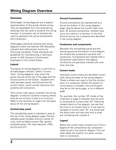
Wiring Diagram Overview<br />
Overview<br />
Volkswagen wiring diagrams are a graphic<br />
representation <strong>of</strong> the actual vehicle wiring.<br />
They are developed from the engineering<br />
drawings that are used to produce the wiring<br />
harness. A consistent set <strong>of</strong> symbols are<br />
used to represent the actual components<br />
and conductors.<br />
Volkswagen electrical systems and wiring<br />
diagrams follow the German DIN (Deutsche<br />
Industrie Norm/Deutsches Institut für<br />
Normung) standards. These standards are<br />
guidelines for manufacturing in Germany,<br />
similar to SAE (Society <strong>of</strong> Automotive<br />
Engineers) in the United States.<br />
Layout<br />
The layout <strong>of</strong> wiring diagrams is common to<br />
all Volkswagen vehicles. Called “Current<br />
Track” wiring diagrams, they show the<br />
power source at the top <strong>of</strong> the page and the<br />
Ground points at the bottom. Situated vertically<br />
between power and Ground are the<br />
current tracks, which contain electrical components<br />
and conductors.<br />
This current track layout simplifies the wiring<br />
diagram. Conductor symbols crossing where<br />
they do not connect is kept to a minimum.<br />
Refer to the example on page 3 for the basic<br />
layout <strong>of</strong> the wiring diagram.<br />
Central/relay panel<br />
The central/relay panel is indicated in gray at<br />
the top <strong>of</strong> the wiring diagram page. The central/relay<br />
panel includes common power circuits,<br />
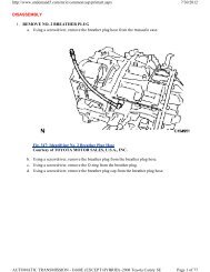
such as battery power (30), ignition<br />
switched power (15), load reduction (75/X),<br />
and Ground (31).<br />
2<br />
Ground Connections<br />
Ground connections are represented as a<br />
line at the bottom <strong>of</strong> the wiring diagram<br />
page, directly above the current track numbers.<br />
All Ground connections, whether they<br />
occur as a splice in a harness, or the final<br />
Ground source, are numbered and identified<br />
in the wiring diagram.<br />
Conductors and components<br />
Between the central/relay panel and the<br />
vehicle ground at the bottom <strong>of</strong> the diagram<br />
are located the component symbols and<br />
conductors. Components are marked with a<br />
component code listed in the legend.<br />
Conductors are generally marked with wire<br />
color and size.<br />
Current tracks<br />
Individual current tracks are identified numerically<br />
along the base <strong>of</strong> the wiring diagram.<br />
These numbers are used to find the continuation<br />
<strong>of</strong> a conductor. Where the system or<br />
circuit layout is complex, this continuation<br />
may be on the same page, or on a different<br />
page.<br />
For example, the number 191 inside <strong>of</strong> the<br />
small box on page 3 indicates that the wire<br />
is continued on current track 191. Following<br />
straight down on the diagram, we see that<br />
this wire is on current track 5. If we were to<br />
navigate to current track 191, we would see<br />
the same color and size wire with a small<br />
box containing the number 5.<br />
Legend<br />
Below the current track numbers you’ll find a<br />
legend <strong>of</strong> the components (by component<br />
code) found in the specific diagram. This will<br />
<strong>of</strong>ten detail the location <strong>of</strong> a given component<br />
or connection.