Temptimer Controls - Indeeco
Temptimer Controls - Indeeco
Temptimer Controls - Indeeco

You also want an ePaper? Increase the reach of your titles
YUMPU automatically turns print PDFs into web optimized ePapers that Google loves.
www.indeeco.com<br />
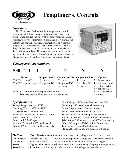
<strong>Temptimer</strong> ® <strong>Controls</strong><br />
Operation<br />
The <strong>Temptimer</strong> Series combines temperature control and<br />
electronic batch timer into one microprocessor-based unit.<br />
Temperature control can be on/off or proportional, heating or<br />
cooling, °F or °C. Features include high and low alarms, fan<br />
outputs and open/shorted sensor protection. J or K thermo-<br />
couple, RTD and thermistor inputs are available. The pilot<br />
duty outputs are triacs to drive contactors or pulsed-DC to<br />
drive solid-state relays. The electronic timer can be count<br />
up or countdown, hours or hours/minutes or minutes/seconds.<br />
Status leds indicate mode of operations and output status.<br />
Catalog and Part Numbers:<br />
530 - TT - 1 T T N - N<br />
Series Output 1 (OP1) Output 2 (OP2) Output 3 (OP3) Options<br />
530-TT-1 = on/off T = triac T = triac T = triac 3 = J thermocouple<br />
530-TT-2 = proportional S = pulsed DC S = pulsed DC S = pulsed DC 4 = K thermocouple<br />
N = none N = none 5 = options 3 & 7<br />
6 = options 4 & 7<br />
Note: RTD and thermistor inputs are standard. 7 = 103 dB beeper<br />
Triac outputs should be used with on/off control. N = none<br />
Specifications Line Voltage: 120VAC or 240VAC, +/− 10%<br />
Storage Temp: -40° to 185°F Frequency: 47 to 63 Hertz, sinewave only<br />
Operating Temp: 32°F to 149°F Power Consumption: 6VA maximum<br />
UL Recognized: File E52105 J or K Thermocouple input: 35 to 880°F<br />
Enclosure: ¼ DIN, plastic, NEMA 1 rating 385 platinum 100Ω RTD input: -60 to 999°F<br />
Panel Cutout: 3.622” square 10K R-T Curve 16, Thermistor input: 32 to 400°F<br />
Front bezel: 3.780” square Triac output: 750mA max, up to 240VAC, pilot-duty<br />
Depth: 4.675” total, 4.15” inside panel Pulsed DC output: 12VDC typical, 50mA max.<br />
Terminal Wires: 18-22 AWG copper only Timer range: 1 second to 240 hours<br />
Standard beeper: 72 dB at a distance of 6 inches<br />
Button User Mode - Actual temperature and timer displayed. Status leds on.<br />
Down Arrow Decrease the value. When actual temperature is displayed, the timer is changed.<br />
Up Arrow Increase the value. When setpoint is displayed, the setpoint is changed.<br />
Mode Toggles the actual or setpoint temperature and steps through the programming menus.<br />
Start/Reset Starts & stops a timer cycle. Mutes a alarm . Resets high and low alarms.
Program Mode In user mode, press & hold Up and Down simultaneously until prog appears.<br />
Step through the parameters with Mode. To exit, press & hold Up and Down.<br />
Parameter Menu Item Description<br />
Sd range: 2-100°F Switching Differential On/off control only. Centered around setpoint.<br />
Pb range: 2-100°F Proportional Band Proportional control only. Centered around setpoint<br />
tP range: 1-100°F Timer Pause Band If the input is outside of this band, the timer stops.<br />
AHi (input range) Absolute High Alarm The actual temperature at which the high alarm occurs.<br />
ALo (input range) Absolute Low Alarm The actual temperature at which the low alarm occurs.<br />
dHi range: 1-250°F Deviation Hi Alarm Added to the setpoint to calculate the alarm.<br />
dLo range: 1-250°F Deviation Lo Alarm Subtracted from the setpoint to calculate the alarm.<br />
Fan range: 0-255 Fan Delay Seconds the fan will be on after a timed cycle ends.<br />
Off range: +/−50°F Sensor Offset Added to or subtracted from the input temperature.<br />
Soft Software Version Non-programmable number for identification only.<br />
Configure Mode In program mode, press & hold Mode and Start/Reset until cnfg appears.<br />
Step through with Mode. To exit, press & hold Mode and Start/Reset.<br />
Parameter Menu Item Description<br />
OP1 range: 1-8 Temperature 1,2,3,4 = on/off 1,3,5,7 = °F 1,2,5,6 = heating<br />
Control Type 5,6,7,8 = proportional 2,4,6,8 = °C 3,4,7,8 = cooling<br />
OP2 range: 1-8 Alarm and 1 = none, 3 = high alarm, 4 = low alarm, 5 = high and low alarm<br />
OP3 range: 1-8 Fan Outputs 6 = fan on during timer, 7 = fan off during timer, 8 = remote beeper<br />
Al range: 1-9 Alarm Type 1 = none, 2 = AHi, 3 = ALo, 4 = dHi, 5 = dLo, 6 = AHI & ALo<br />
(see above) 7 = dHi & dLO, 8 = AHi & dLo, 9 = dHi & ALo<br />
nPut range: 1-4 Input Type 1 = thermistor, 2 = rtd, 3 = J type T/C, 4 = K type T/C<br />
tt range: 1-8 User Mode (see table below)<br />
tine range: 1-12 Timer Type 1,2,3,4,5,6 = down 1,2,7,8 = MM:SS 1,3,5,7,9,11 = short beep<br />
and End of 7,8,9,10,11,12 = up 3,4,9,10 = HH:MM 2,4,6,8,10,12 = beep<br />
Cycle Beeper 5,6,11,12 = HHH until Start/Reset pushed<br />
beep range: 1-6 Beeper Rate 1 = on, 2 = 1/sec, 3 = 2/sec, 4 = 4/sec, 5 = 8/sec, 6 = off<br />
User Mode - Temperature and Timer Relationships<br />
1 = temperature control and timer are independent 5 = timer completely disabled<br />
2 = temperature control runs during timer 6 = 1 with the timer pause feature (see above)<br />
3 = timer starts automatically after setpoint is reached. 7 = 2 with the timer pause feature (see above)<br />
Pre Heat will flash until the timer starts 8 = 3 with the timer pause feature (see above)<br />
4 = same as 3 except the timer will not start until the 9 = 4 with the timer pause feature (see above)<br />
Start/Reset button is pressed. Push Strt will flash<br />
INDEECO CONTROLS<br />
425 Hanley Industrial Court<br />
St. Louis, MO 63144<br />
phone: 314-644-4300<br />
fax: 314-644-5332<br />
www.indeeco.com<br />
Rear Terminal Wiring (see Configure Mode for output setup)<br />
17 & 18 = RTD or thermistor input 10 = OP1, triac or DC pulse “-“<br />
1 = J or K thermocouple “-“ 11 = OP1, triac or DC pulse “+”<br />
2 = J or K thermocouple “+” 15 = OP2, triac or DC pulse “+“<br />
13 & 14 = 120VAC power input 16 = OP2, triac or DC pulse “-”<br />
12 & 14 = 240VAC power input 8 = OP3, triac or DC pulse “-“<br />
9 = OP3, triac or DC pulse “+”<br />
Note: Triac outputs do not have power connected nor sourced internally.<br />
85-2252-83