Electronic Thermostat - C1025 For Modulating Electric ... - Indeeco
Electronic Thermostat - C1025 For Modulating Electric ... - Indeeco
Electronic Thermostat - C1025 For Modulating Electric ... - Indeeco

You also want an ePaper? Increase the reach of your titles
YUMPU automatically turns print PDFs into web optimized ePapers that Google loves.
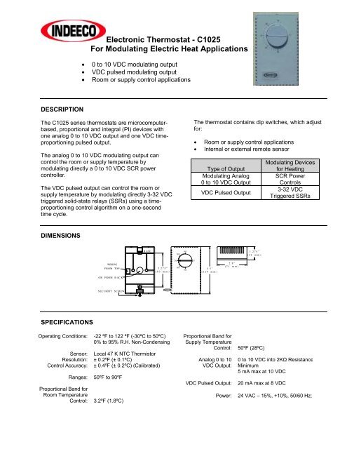
<strong>Electronic</strong> <strong>Thermostat</strong> - <strong>C1025</strong><br />
<strong>For</strong> <strong>Modulating</strong> <strong>Electric</strong> Heat Applications<br />
• 0 to 10 VDC modulating output<br />
• VDC pulsed modulating output<br />
• Room or supply control applications<br />
DESCRIPTION<br />
The <strong>C1025</strong> series thermostats are microcomputerbased,<br />
proportional and integral (PI) devices with<br />
one analog 0 to 10 VDC output and one VDC timeproportioning<br />
pulsed output.<br />
The analog 0 to 10 VDC modulating output can<br />
control the room or supply temperature by<br />
modulating directly a 0 to 10 VDC SCR power<br />
controller.<br />
The VDC pulsed output can control the room or<br />
supply temperature by modulating directly 3-32 VDC<br />
triggered solid-state relays (SSRs) using a timeproportioning<br />
control algorithm on a one-second<br />
time cycle.<br />
The thermostat contains dip switches, which adjust<br />
for:<br />
• Room or supply control applications<br />
• Internal or external remote sensor<br />
Type of Output<br />
<strong>Modulating</strong> Analog<br />
0 to 10 VDC Output<br />
VDC Pulsed Output<br />
<strong>Modulating</strong> Devices<br />
for Heating<br />
SCR Power<br />
Controls<br />
3-32 VDC<br />
Triggered SSRs<br />
DIMENSIONS<br />
BASE<br />
80<br />
90<br />
1.275"<br />
(32 mm)<br />
WIRING<br />
FROM TOP<br />
3.275"<br />
(83 mm)<br />
70<br />
60<br />
50<br />
F<br />
4.5"<br />
(114 mm)<br />
2.8"<br />
(71 mm)<br />
OR FROM BACK<br />
SECURITY SCREW<br />
SPECIFICATIONS<br />
Operating Conditions:<br />
Sensor:<br />
Resolution:<br />
Control Accuracy:<br />
Proportional Band for<br />
Room Temperature<br />
Control:<br />
-22 ºF to 122 ºF (-30ºC to 50ºC)<br />
0% to 95% R.H. Non-Condensing<br />
Local 47 K NTC Thermistor<br />
± 0.2ºF (± 0.1ºC)<br />
± 0.4ºF (± 0.2ºC) (Calibrated)<br />
Ranges: 50ºF to 90ºF<br />
3.2ºF (1.8ºC)<br />
Proportional Band for<br />
Supply Temperature<br />
Control:<br />
Analog 0 to 10<br />
VDC Output:<br />
VDC Pulsed Output:<br />
Power:<br />
50ºF (28ºC)<br />
0 to 10 VDC into 2KΩ Resistance<br />
Minimum<br />
5 mA max at 10 VDC<br />
20 mA max at 8 VDC<br />
24 VAC – 15%, +10%, 50/60 Hz;
ANALOG 0 TO 10 VDC MODULATING<br />
OUTPUT The analog 0 to 10 VDC modulating<br />
output can control the room or supply temperature<br />
by modulating directly 0 to 10 VDC signal to the<br />
SCR power controller.<br />
Use only one of the outputs, not both at the<br />
same time.<br />
VDC PULSED MODULATING OUTPUT<br />
The VDC pulsed output can control the room or<br />
supply temperature by modulating directly 3-32 VDC<br />
triggered solid-state relays (SSR) using a timeproportioning<br />
control algorithm on a 1 second time<br />
cycle.<br />
Example:<br />
PI<br />
Demand Time On Time Off<br />
Total<br />
Cycle<br />
50% ½ sec. ½ sec. 1 sec.<br />
25% ¼ sec. ¾ sec. 1 sec.<br />
This time-proportioning output cannot be used on<br />
regular mechanical relays or contactors.<br />
THERMOSTAT INSTALLATION<br />
IMPORTANT – <strong>Electronic</strong> controllers require<br />
special care for wiring and start-up. To avoid<br />
problems, carefully follow the procedures below.<br />
Be sure to have all the literature on hand for all<br />
components installed: controller, actuators, relay,<br />
etc.<br />
Look at the wiring diagrams and study them<br />
carefully. Be sure that you understand how the<br />
system is supposed to work.<br />
Make the wiring according to the wiring diagrams.<br />
Respect polarity for power terminals 3 and 4<br />
between multiple controllers if the same transformer<br />
is used.<br />
• Remove security screw on left side of thermostat<br />
cover.<br />
• Open up by pulling on the bottom side of<br />
thermostat.<br />
Use only one of the outputs, not both at the<br />
same time.<br />
REMOTE SENSOR A remote sensor can be<br />
wired and used with the <strong>C1025</strong> thermostat. To wire<br />
a remote sensor, set dip switch S2 to position 0 (off).<br />
If the application is for discharge air or supply<br />
temperature control, set dip switch S1 to<br />
position 1 (on). This will enable a larger proportional<br />
band, making the controlled temperature more<br />
stable. Duct sensor, part number 1016942, is<br />
required.<br />
Characteristics of remote sensor 47 KΩ.<br />
Temperature<br />
ºF<br />
Temperature<br />
ºC<br />
Sensor<br />
Resistance<br />
150.0 ºF 65.6º C 9.610 Kohm<br />
140.0 ºF 60.0º C 11.700 Kohm<br />
130.0 ºF 54.4º C 14.342 Kohm<br />
120.0 ºF 48.9º C 17.682 Kohm<br />
110.0 ºF 43.3º C 21.940 Kohm<br />
100.0 ºF 37.8º C 27.412 Kohm<br />
90.0 ºF 32.2º C 34.483 Kohm<br />
80.0 ºF 26.7º C 43.704 Kohm<br />
70.0 ºF 21.1º C 55.834 Kohm<br />
60.0 ºF 15.6º C 71.866 Kohm<br />
50.0 ºF 10.0º C 93.340 Kohm<br />
40.0 ºF 4.4º C 122.298 Kohm<br />
A) Location<br />
1. Should not be installed on outside wall.<br />
2. Must be installed away from any heat<br />
source.<br />
3. Should not be affected by direct sun<br />
radiation.<br />
4. Nothing must restrain vertical air circulation<br />
to the thermostat.<br />
B) Installation<br />
1. Pull out cables 6" out of the wall.<br />
2. Wall surface must be flat and clean.<br />
3. Separate the thermostat and the base by<br />
pulling the cover by the bottom (same as the<br />
security screw).<br />
4. Insert cable in the central hole of the base.<br />
5. Align the base and mark the location of the<br />
two mounting holes on the wall. Install<br />
proper side of base up.<br />
6. Install anchors in the wall.<br />
7. Insert screws in mounting holes on each side of<br />
the base. DO NOT OVERTIGHTEN!<br />
8. Strip each wire ¼ inch.<br />
9. Insert each wire according to wiring<br />
diagram.<br />
10. Reinstall the cover (top side first) and gently<br />
push back extra wire length in the hole in the<br />
wall.<br />
11. Install security screw.<br />
INDEECO – 425 Hanley Industrial Court – St. Louis, MO 63144 – Phone: 314-644-4300 – Fax: 314-644-5332<br />
www.indeeco.com<br />
85-2655-89-2<br />
I:\WP\02\FORMS\FM14\<strong>C1025</strong>A.DOC
DIP SWITCH ADJUSTMENTS PER<br />
APPLICATIONS<br />
S1<br />
APPLICATION SWITCH<br />
0 <strong>For</strong> regular room control applications.<br />
Proportional bank is 3.2ºF (1.8ºC)<br />
1 <strong>For</strong> discharge air or supply temperature control<br />
Proportional bank is 50ºF (28ºC)<br />
S3 switch is not used.<br />
S2<br />
MAIN TEMPERATURE SENSOR<br />
0 Main temperature sensor is remote mounted<br />
1 <strong>Thermostat</strong> internal sensor for room<br />
temperature sensing<br />
Option K Heater With INDEECO Furnished<br />
Duct Or Room <strong>Thermostat</strong><br />
Special Option K Heater Using Pulse Modulation With<br />
INDEECO Furnished Duct Or Room <strong>Thermostat</strong><br />
Option G Heater With INDEECO Furnished Duct Or<br />
Room <strong>Thermostat</strong><br />
INDEECO – 425 Hanley Industrial Court – St. Louis, MO 63144 – Phone: 314-644-4300 – Fax: 314-644-5332<br />
www.indeeco.com<br />
85-2655-89-2<br />
I:\WP\02\FORMS\FM14\<strong>C1025</strong>A.DOC