Contactless Sensors for Surface Electromyography - Geert's pages
Contactless Sensors for Surface Electromyography - Geert's pages
Contactless Sensors for Surface Electromyography - Geert's pages

You also want an ePaper? Increase the reach of your titles
YUMPU automatically turns print PDFs into web optimized ePapers that Google loves.
Proceedings of the 28th IEEE<br />
EMBS Annual International Conference<br />
New York City, USA, Aug 30-Sept 3, 2006<br />
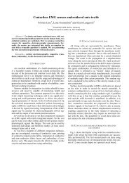
<strong>Contactless</strong> sensors <strong>for</strong> <strong>Surface</strong> <strong>Electromyography</strong><br />
Lena Gourmelon and Geert Langereis<br />
Philips Research, Eindhoven, The Netherlands<br />
lena.gourmelon@philips.com, geert.langereis@philips.com<br />
Abstract— Muscle activity can be monitored by measuring<br />
the <strong>Surface</strong> <strong>Electromyography</strong> (SEMG) signal at the surface<br />
of the body. The SEMG signal is a combination of several<br />
activation signals sent through the muscle fibers triggering the<br />
contraction of the muscle. SEMG enables to access those signals<br />
non-invasively.<br />
Usually, metal plate electrodes in combination with electrolytic<br />
gel are placed in direct contact with the skin to measure SEMG.<br />
For prolonged monitoring of the muscle activity, this type of<br />
electrodes is not com<strong>for</strong>table and can cause skin irritation.<br />
In this paper, we demonstrate capacitive electrodes capable<br />
of sensing the SEMG signal. These contactless electrodes do<br />
not require direct contact with the skin and thus they can be<br />
suitable <strong>for</strong> prolonged monitoring of the muscle activity.<br />
I. INTRODUCTION<br />
Work related musculoskeletal disorders, mainly back pain<br />
and repetitive strain injury (RSI), are among the main<br />
international health and safety problems among workers<br />
nowadays. People suffering from this kind of injury would<br />
benefit from a continuous monitoring of their muscles activity.<br />
Another important aspect is to prevent musculoskeletal<br />
disorders <strong>for</strong> people at risk, which could also be done by a<br />
continuous monitoring of their muscles activity.<br />
To enable continuous monitoring of <strong>Surface</strong> <strong>Electromyography</strong><br />
(SEMG), a non-invasive type of electrodes should be<br />
used. Such a system should be wearable and com<strong>for</strong>table to<br />
enable the user to use it while per<strong>for</strong>ming his/her regular<br />
activities.<br />
Existing electrodes employed to record SEMG signals are<br />
usually metal plates electrodes combined with an electrolytic<br />
gel placed in direct contact with the skin. This type of<br />
electrode acts as an electric transducer converting the ionic<br />
current flowing in the body to an electronic current flowing<br />
in the electrode lead to the measurement device. By<br />
principle, these electrodes require direct electrical contact<br />
with the body. An alternative type of electrode has been<br />
proposed in literature. These electrodes [1][2][3][4], referred<br />
to as contactless electrodes, couple capacitively to the body<br />
detecting in this way a displacement current instead of a real<br />
charge current. There<strong>for</strong>e no direct electrical contact between<br />
the body and the electrode is required. While the previous<br />
publications use contactless sensors <strong>for</strong> monitoring ECG, we<br />
are using such sensors <strong>for</strong> monitoring muscles by means of<br />
SEMG. <strong>Contactless</strong> electrodes are perfectly suitable <strong>for</strong> a<br />
continuous measurement of the SEMG signal.<br />
Avoiding the contact with skin and the use of electrolytic<br />
gel prevent irritation of the skin. Moreover, the contactless<br />
electrodes can be integrated in a wearable system, which<br />
1-4244-0033-3/06/$20.00 ©2006 IEEE. 2514<br />
FrB05.4<br />
does not require a permanent good contact with the patient’s<br />
body. The ConText project, funded by the European Commission,<br />
which started in 2006, is working on the integration<br />
of such electrodes into textile [6]. In this way, the user could<br />
wear a shirt or a vest with integrated sensors to measure<br />
continuously the SEMG signal from selected muscles.<br />
In this paper, we present our results on the used contactless<br />
electrodes <strong>for</strong> SEMG. In particular, the noise measurements<br />
from the capacitive electrodes are shown. We present the first<br />
SEMG measurements obtained with the contactless sensors<br />
separated from the skin by a piece of cotton fabric.<br />
II. INTRODUCTION TO SURFACE ELECTROMYOGRAPHY<br />
Musculoskeletal disorders can be monitored by specialists<br />
analyzing electrical signals which cause muscle contraction.<br />
Muscles are constituted from muscle fibers. Motoneurons in<br />
the nervous system are connected to these muscle fibers, each<br />
combination of a Motoneuron with the connected muscle<br />
fibers constitutes a Motor Unit (MU) [5]. The activity of one<br />
muscle is controlled through several MUs. Different types of<br />
MUs exist, corresponding to different intensity and duration<br />
of the ef<strong>for</strong>t. MUs are recruited depending on the type<br />
of ef<strong>for</strong>t. When a MU is recruited, the Motoneuron sends<br />
a current through the connected fibers. The SEMG signal<br />
corresponds to the action potentials created by the current<br />
flowing through the muscle fibers. This signal varies in<br />
frequency during the ef<strong>for</strong>t. When measuring SEMG on top<br />
of the skin covering a muscle, the action potential recorded<br />
is an average of all the action potentials from the MUs under<br />
the electrode area. Assessing these signals enables specialists<br />
to understand and monitor musculoskeletal problems. The<br />
<strong>Surface</strong> EMG signal is normally measured by using two<br />
electrodes <strong>for</strong> a differential recording on top of a muscle. The<br />
electrodes should be placed at two different locations along<br />
the same muscle. The frequency of interest <strong>for</strong> the SEMG<br />
signals are in the range 10 - 500 Hz, and the maximum<br />
amplitude is about 1mV pp, depending on the size and depth<br />
of the muscle.<br />
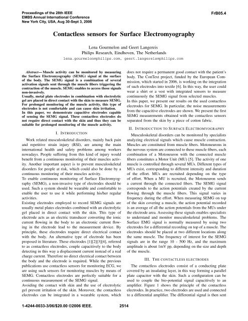
III. THE CONTACTLESS ELECTRODES<br />
The contactless electrodes consist of a conducting plate<br />
covered by an insulating layer, in this way <strong>for</strong>ming a parallel<br />
plate capacitor with the skin. Such a configuration can be<br />
used to couple the bio-potential signal capacitively to an<br />
amplifier. Figure 1 shows the principle of the contactless<br />
electrodes. In practice, two electrodes are used and connected<br />
to a differential amplifier. The differential signal is then sent
<strong>Surface</strong><br />
potential<br />
V<br />
Electrode plate<br />
Guard ring<br />
skin<br />
+<br />
−<br />
contactless electrodes<br />
Fig. 1. <strong>Contactless</strong> electrodes principle<br />
Amplifier <strong>for</strong> impedance conversion<br />
and active shielding<br />
+<br />
−<br />
+<br />
−<br />
A = 11<br />
Measurement<br />
system<br />
Fig. 2. Schematic of one contactless electrode with impedance conversion<br />
and active shielding<br />
to the measurement system to be sampled, processed and<br />
analyzed.<br />
Because of the small size of the electrode and the distance<br />
of the electrode plate to the conductive layer of the skin,<br />
the capacitance value of the electrode is very low and<br />
hence results in a very high input impedance of our sensor<br />
(estimated capacitance is in the order of 0.6 pF at 1 mm<br />
from the body surface). Due to this high impedance, the<br />
signal at the output of the sensor is very sensitive to all<br />
kind of interference signals. Two techniques are used in<br />
the design of the electrode to reduce interferences. First,<br />
an impedance converter circuit (a unity gain amplifier) is<br />
placed directly next to the electrode plate to convert the<br />
high impedance to a low impedance which is less sensitive<br />
to capacitive noise from the environment. Secondly, a<br />
guard ring is placed around the electrode to per<strong>for</strong>m active<br />
shielding (bootstrapping). The unity gain amplifier used <strong>for</strong><br />
the impedance conversion is also used to drive the guard at<br />
the same potential as the electrode plate. Figure 2 shows a<br />
schematic of the circuit constituting one contactless electrode<br />
with the amplifier used <strong>for</strong> both impedance conversion and<br />
active shielding. A second amplifier is used to amplify the<br />
electrode signal with a gain equal to 11. The electronic<br />
components on the electrode are placed in a shielded box.<br />
Figure 3 shows the noise spectrum obtained from such a<br />
sensor. The sensor is connected to a metal box containing<br />
the batteries <strong>for</strong> powering the sensor, which is then connected<br />
to a PC containing a NI 4472 24 bits sampling card.<br />
The electrode was placed above a grounded metal plate to<br />
2515<br />
prevent the sensor from picking up any signal. The sampling<br />
frequency is equal to 1 kHz. The noise spectrum corresponds<br />
to the noise from the electronics. Notably, 1/f noise from the<br />
amplifiers can be observed in the spectrum. The slope which<br />
can be observed at the end of the spectrum is due to the<br />
anti-aliasing filter integrated in the sampling card. The cutoff<br />
frequency of this filter is equal to half of the sampling<br />
frequency. The noise level is in the order of 1 μV/ √ Hz @10<br />
Hz <strong>for</strong> a resolution bandwidth of 1 Hz. Since the SEMG<br />
signal of interest is normally in the order of 1 mV pp in<br />
the frequency band 10 - 500 Hz, the noise floor is quite<br />
acceptable.<br />
To per<strong>for</strong>m our measurements presented below in this section<br />
and in section IV, we used the following set-up. Two<br />
contactless sensors were placed along the biceps brachii of<br />
a test person, while a layer of cotton fabric with a thickness<br />
of 0.99 mm separated the sensors from the skin surface. We<br />
fixed the electrodes and the piece of cotton fabric to make<br />
sure that the distance between the electrodes with respect to<br />
the skin surface remained constant. The two electrodes have<br />
a round shape of 12 mm diameter. The distance between<br />
the two electrodes was equal to 37 mm from center to<br />
center. Both electrodes have an amplification gain equal to<br />
11. The signals coming from both electrodes are sent to<br />
the PC containing the NI 4472 sampling card. The signals<br />
from the two electrodes were sampled simultaneously at a<br />
sampling frequency of 1 kHz, an anti-aliasing filter with a<br />
cut-off frequency equal to half of the sampling frequency<br />
was applied be<strong>for</strong>e sampling. After sampling, the signals<br />
from the two electrodes were digitally subtracted to obtain<br />
a differential signal, which is normalized by the electrode<br />
amplification gain to calculate the real surface potential.<br />
During the following presented measurements, we used the<br />
same above-described set-up.<br />
Despite the design techniques applied to reduce the external<br />
disturbances on the signal, interferences due to the electric<br />
wiring in the building are still present in the signal because<br />
they are directly transmitted through the body. The body<br />
capacitively couples to the voltage sources in the room and<br />
there is always a potential difference between two positions<br />
on the body. The impact on the measurements, however, can<br />
be reduced by proper grounding as shown with the following<br />
experiment. The differential signal between the two sensors<br />
was recorded under two different conditions. In the first case,<br />
nothing was used to ground the test person. In the second<br />
case, the test person was grounded by touching the metallic<br />
box, which contains the batteries to power the sensors. The<br />
metallic box is connected to the ground of the computer, thus<br />
by touching the box, the test person was also connected to the
Noise spectral density (V H−1/2<br />
Spectral density (V/sqrt(Hz))<br />
10 −2<br />
10 −3<br />
10 −4<br />
10 −5<br />
10 −6<br />
10 −7<br />
10<br />
0 50 100 150 200 250 300 350 400 450 500<br />
−8<br />
Frequency (Hz)<br />
Fig. 3. Noise spectrum from the contactless sensors<br />
10 −1<br />
10 −2<br />
10 −3<br />
10 −4<br />
10 −5<br />
10 −6<br />
Test person not grounded<br />
Test person grounded<br />
10<br />
0 50 100 150 200 250 300 350 400 450 500<br />
−7<br />
Frequency (Hz)<br />
Fig. 4. Spectrum of the differential signal obtained with the electrodes<br />
along the biceps brachii of a test person with a layer of cotton between the<br />
electrodes and the skin surface.<br />
ground of the computer. Figure 4 shows the two spectrums<br />
obtained from the differential signals when the patient is not<br />
grounded and when the patient is grounded. When the patient<br />
is not grounded, the harmonics of the 50 Hz interference<br />
signal can be clearly observed in the spectrum, and the<br />
interferences are highly attenuated when the test person is<br />
grounded<br />
The 50 Hz interferences are dominating in the signal if the<br />
test person is not connected to ground. There<strong>for</strong>e, during<br />
the following presented measurements, the test person was<br />
connected to the ground. Even after grounding, some interferences<br />
remain at 50 Hz. However, those can be canceled<br />
by a 50 Hz (digital) notch filter if needed.<br />
IV. FIRST SEMG MEASUREMENTS WITH THE<br />
CONTACTLESS ELECTRODES<br />
The SEMG measurements were per<strong>for</strong>med in the same<br />
conditions as described in section III. This time, the biceps<br />
brachii was contracted by lifting a weight of 2.5 kg. The<br />
2516<br />
Signal Amplitude (Volts)<br />
0.5<br />
0<br />
−0.5<br />
−1<br />
x 10−3<br />
1<br />
Signal during contraction<br />
Signal during resting period<br />
−1.5<br />
0 0.1 0.2 0.3 0.4 0.5 0.6 0.7 0.8 0.9 1<br />
Time (s)<br />
Fig. 5. Continuous contraction of the biceps brachii measured with<br />
contactless electrodes.<br />
differential signal coming from the electrodes was filtered.<br />
The filtering part consisted of a single notch filter to remove<br />
the 50 Hz interference and a high-pass filter with a cut-off<br />
frequency fc=10 Hz. Since the test person was connected to<br />
ground, most of the interferences from 50 Hz to 450 Hz were<br />
canceled as was explained, but an additional interference at<br />
50 Hz remains with a non-negligible amplitude, a notch filter<br />
at 50 Hz was used to remove it. Low frequency disturbances<br />
due to small movements and breathing of the test person<br />
are removed by a 10 Hz high-pass filter. Figure 5 shows<br />
the differential recorded signals during respectively, 1 second<br />
of contraction and 1 second of rest. We can notice a clear<br />
amplitude difference between the contraction signal and the<br />
resting signal, SEMG is there<strong>for</strong>e correctly detected by the<br />
contactless electrodes. From the previous measurement, two<br />
parts of the signal were selected, one corresponding to 30<br />
seconds of resting period and one corresponding to 30 second<br />
of contraction period, to compare their spectral content.<br />
Figure 6 shows the spectrums of respectively, the resting<br />
part and the contraction part of the previous signal. The<br />
contraction signal recorded with the contactless electrodes<br />
can be clearly distinguished from the resting signal recorded<br />
with the same electrodes. The spectrums show a difference<br />
of about 16 dB between the two signals, which is enough<br />
to distinguish the contraction from the resting period. These<br />
measurements show that it is possible to use the contactless<br />
electrodes to detect the SEMG signal from a contracted<br />
muscle.<br />
V. CONCLUSIONS AND FUTURE WORK<br />
We propose to use the technology of contactless electrodes<br />
to sense the <strong>Surface</strong> <strong>Electromyography</strong> signal in order to<br />
have a continuous monitoring of the muscle activity. The<br />
first SEMG measurements with the contactless electrodes
Spectral density (V/sqrt(Hz))<br />
10 −2<br />
10 −3<br />
10 −4<br />
10 −5<br />
10 −6<br />
10 −7<br />
Spectrum of signal obtained during 30 seconds of rest<br />
Spectrum of the signal obtained during 30 seconds of contraction<br />
10<br />
0 50 100 150 200 250 300 350 400 450 500<br />
−8<br />
Frequency (Hz)<br />
Fig. 6. Spectrums of the measured signals during respectively 30 seconds<br />
of contraction and 30 seconds of rest<br />
show that it is possible to detect the SEMG signal on a<br />
the biceps of a test person, with a layer of cotton fabric<br />
separating the electrodes from the skin. Our future work will<br />
be concentrated on improving the measurement set-up and<br />
the sensor design in terms of robustness against interferences.<br />
We would also like to prevent the need in grounding the body<br />
and find another solution to reduce interferences. A possible<br />
solution of using a capacitive feed-back circuit has already<br />
been introduced in literature [7].<br />
VI. ACKNOWLEDGMENTS<br />
We thank the European Commission <strong>for</strong> funding part<br />
of this work under contract IST-027291 (ConText). We<br />
thank the ConText project partners: Clothing+ (Finland),<br />
Katholieke Universiteit Leuven (Belgium), TITV (Germany),<br />
TNO (the Netherlands)and Technische Universität Berlin<br />
(Germany).<br />
REFERENCES<br />
[1] R.J. Prance, A. Debray, T.D. Clark, H. Prance, M. Nock, C.J. Harland<br />
and A.J. Clippingdale, ”An ultra-low-noise electrical-potential probe<br />
<strong>for</strong> human-body scanning”, Meas. Sci. Technol., vol. 11, 2000, pp<br />
291-297.<br />
[2] P.C. Richardson, ”The insulated electrode: A pasteless electrocardiographic<br />
technique”, Annu. Proc. Conf. Eng. Med. Biol., vol. 20, 1967.<br />
[3] W.H. Ko, M.R. Neumann, R.N. Wolfson and E.T. Yon, ”Insulated Active<br />
Electrodes”, IEEE Transactions on Industrial Electronic Control<br />
Instruments, 17, 1970, pp. 195-197.<br />
[4] Ko Keun Kim, Yong Kiu Lim and Kwang Suk Park, ”The electrically<br />
noncontacting ECG measurement on the toilet seat using the<br />
capacitively-coupled insulated electrodes”, Proc. IEEE of the 26th<br />
EMBS conference, 2004.<br />
[5] G.R. Langereis et al., ”CONTEXT: <strong>Contactless</strong> sensors <strong>for</strong> body<br />
monitoring incorporated into textile”, Conference Fibermed, 2006.<br />
[6] R. Merletti and P.A. Parker (eds.), <strong>Electromyography</strong>, Physiology,<br />
Engineering and Noninvasive Applications, Wiley Interscience, 2004,<br />
ISBN 0-471-67580-6.<br />
2517<br />
[7] Ko Keun Kim, Yong Kiu Lim and Kwang Suk Park, ”Common Mode<br />
Noise Cancellation <strong>for</strong> Electrically Non-Contact ECG Measurement<br />
System on a Chair”, Proc. IEEE of the 27th EMBS conference, 2005.