Contactless EMG sensors embroidered onto textile - Geert's pages
Contactless EMG sensors embroidered onto textile - Geert's pages
Contactless EMG sensors embroidered onto textile - Geert's pages

Create successful ePaper yourself
Turn your PDF publications into a flip-book with our unique Google optimized e-Paper software.
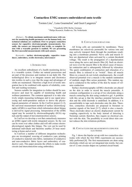
<strong>Contactless</strong> <strong>EMG</strong> <strong>sensors</strong> <strong>embroidered</strong> <strong>onto</strong> <strong>textile</strong><br />
Torsten Linz 1 , Lena Gourmelon 2 and Geert Langereis 2<br />
Abstract— To obtain maximum unobtrusiveness with <strong>sensors</strong><br />
for monitoring health parameters on the human body, two<br />
technical solutions are combined. First we propose contactless<br />
<strong>sensors</strong> for capacitive electromyography measurements. Secondly,<br />
the <strong>sensors</strong> are integrated into <strong>textile</strong>, so complete fusion<br />
with a wearable garment is enabled. We are presenting<br />
the first successful measurements with such <strong>sensors</strong>.<br />
Keywords— surface electromyography, capacitive transducer,<br />
embroidery, <strong>textile</strong> electronics, interconnect<br />
I. INTRODUCTION<br />
An excellent embodiment of a health monitoring device<br />
is a wearable system. Clothes are natural possessions and<br />
are part of the processes and routines in our daily life. The<br />
technological drive is to integrate <strong>sensors</strong> and electronics<br />
into <strong>textile</strong>s in such a way that the usage and advantages of<br />
cloths are maintained. Therefore a high level of <strong>textile</strong> integration<br />
has to be combined with aspects of reliability, comfort<br />
and washing resistance.<br />
Sensors suitable for integration in clothes should be noninvasive<br />
and must be capable of monitoring health and<br />
wellness parameters. The common approach is to take relatively<br />
simple measuring techniques and to use signal processing<br />
and multi-parameter analysis to derive the physiological<br />
parameters of interest. In the ConText project [1-3],<br />
the universal measurement method of surface electromyography<br />
(s<strong>EMG</strong>) is used from which information about fatigue<br />
is derived by signal processing. Interpretation of the s<strong>EMG</strong><br />
signal may be assisted by electrocardiography (ECG) signals<br />
and the output of movement/position <strong>sensors</strong>.<br />
In ConText we develop a vest that contactlessly measures<br />
an s<strong>EMG</strong> signal with <strong>textile</strong> integrated <strong>sensors</strong>. So the vest<br />
can be worn over other clothes and will still extract electrophysiological<br />
signals like fatigue. The vest can be used by<br />
untrained individuals and therefore enables 24 hour monitoring<br />
at home and at work.<br />
In ConText a number of different integration technologies<br />
are investigated: weaving of conductive yarn, printing<br />
of conductive material <strong>onto</strong> fabric, lamination of conductive<br />
and non-conductive fabric layers and embroidery of conductive<br />
yarn. This paper presents the efforts to make <strong>textile</strong><br />
circuits and interconnections using embroidery.<br />
1 Fraunhofer IZM, Berlin, Germany<br />
2 Philips Research, Eindhoven, The Netherlands<br />
II. CONTACTLESS SURFACE <strong>EMG</strong><br />
All living cells are surrounded by membranes. These<br />
membranes are selectively permeable for various ions and<br />
may actively transport them through the membrane resulting<br />
into a membrane potential. Nerve cells and muscle fibres<br />
are depolarized when activated by a certain threshold<br />
voltage. The result is the propagation of a depolarization<br />
wave along the nerve and muscle fibre [4]. Such an electrical<br />
wave over the muscle fibre is the direct cause of muscular<br />
contraction and is subsequently followed by relaxation.<br />
The quick combination of contraction and relaxation of a<br />
muscle fibre is referred to as “twitch”. Since all muscle<br />
fibres in a muscle do not twitch simultaneously, the overall<br />
observed potential over a muscle is the random summation<br />
of multiple single fibre action potentials. This random signal<br />
is conducted to the surface of the skin by means of volume<br />
conduction.<br />
Surface electromyography (s<strong>EMG</strong>) electrodes are placed<br />
on the skin in order to record the muscle potentials. A<br />
common configuration is a set-up of two electrodes along a<br />
muscle contacting the skin using conductive gel. A problem<br />
with this set-up is that the interface potential between the<br />
skin and the solid electrode is undefined. In addition, it is<br />
uncomfortable to tape such electrodes <strong>onto</strong> the skin. Therefore,<br />
contactless electrodes are proposed in literature to<br />
monitor signals of the heart [5-7], which is also a muscle.<br />
These electrodes detect an electric displacement current by<br />
coupling capacitively to the body instead of detecting a<br />
Nernstian current; therefore, they require no electrical contact<br />
with the skin. The possibility to avoid direct skin contact<br />
reduces the skin irritations problems.<br />
III. CONTACTLESS <strong>EMG</strong> MEASUREMENTS USING PCB<br />
ELECTRODES<br />
Fig. 1 shows the bipolar set-up with two contactless electrodes<br />
with which the first <strong>EMG</strong> experiments are successfully<br />
performed [8]. The first measurements are done using<br />
electrodes which are not yet integrated into <strong>textile</strong>, but consist<br />
of 12 mm circular shapes on a printed circuit board.
Impedance<br />
converters<br />
Local ground<br />
AD Converter<br />
Fig. 1 Set-up for contactlessly sensing <strong>EMG</strong> signals<br />
Because of the capacitive coupling, the impedance of the<br />
sensor is extremely high. The result is that environmental<br />
noise is easily picked up. This problem is solved by placing<br />
an impedance converter directly on top of the electrode. The<br />
electrode is actively shielded by feeding back the output<br />
signal of the local amplifier to a metal cap over the electrode.<br />
The individual sensor output signals are fed into an<br />
analogue to digital converter after anti-aliasing filtering.<br />
Fig. 2 shows the measured <strong>EMG</strong> signal on the biceps<br />
while lifting a weight of 2.5 kg with a 90 degrees bended<br />
arm. The contactless <strong>sensors</strong> have an electrode spacing of<br />
37 mm and a gain of 11. It is compared to a commercial<br />
active s<strong>EMG</strong> electrode (B&L Engineering type BL-AE-N)<br />
having a spacing of 20.6 mm and a gain of 346. In Fig. 2,<br />
the signals are normalized by the gains to give the skin<br />
surface voltage. Note that it is not possible to perform the<br />
two recordings simultaneously.<br />
<strong>EMG</strong> Amplitude [mV]<br />
1<br />
0.5<br />
0<br />
-0.5<br />
+ -<br />
2½kg Active contact electrode<br />
<strong>Contactless</strong> electrode<br />
-1 0 0.1 0.2 0.3 0.4 0.5<br />
Time [sec]<br />
Fig. 2 Recorded <strong>EMG</strong> signals with both an active- and a contactless electrode<br />
In fig. 3, the spectra are shown for the two measurement<br />
methods using the same data set as in fig. 2. As a reference,<br />
the spectra during rest are plotted as well. We can see that<br />
the contactless electrodes and the commercial active s<strong>EMG</strong><br />
electrodes provide similar signal levels and shapes. Only the<br />
bottom noise during rest is a little bit higher. The bandwidth<br />
of the contactless electrode set-up is adequate and comparable<br />
to the reference measurement.<br />
Vrms [dBV]<br />
-60<br />
-80<br />
-100<br />
-120<br />
-140<br />
-160<br />
Exercise<br />
Rest<br />
Active contact electrode<br />
<strong>Contactless</strong> electrode<br />
-180<br />
0 100 200 300 400 500<br />
Frequency [Hz]<br />
Fig. 3 Spectra of the recorded <strong>EMG</strong> signals with both an active- and<br />
contactless electrode<br />
IV. THE ELECTRONIC MODULE<br />
Textile structures are orders of magnitude larger than<br />
electronics structures. Therefore a dimension adapter is<br />
required. As proposed in [9] we used a so called interposer<br />
for that purpose. This is a flexible polymer substrate which<br />
carries the electronics and has conductive pads to connect<br />
the conductive <strong>textile</strong> structures.<br />
Although <strong>textile</strong> structures are big it is advisable to<br />
miniaturize the electronics to archive an overall <strong>textile</strong> character<br />
and to improve the reliability. E.g. thinned silicon<br />
chips are flexible and therefore in a mechanically stressed<br />
environment more reliable. However miniaturization is very<br />
expensive and it is often difficult to find bare dies. Therefore<br />
we have only produced a limitedly miniaturized sensor<br />
electronics module for the first tests with an amplifier in an<br />
SO8 package as shown on the picture.<br />
A 25µm polyimide flex foil was used as substrate and<br />
was structured with a 25µm thin layer of copper-nickel-gold<br />
metallisation and coated with a 15µm layer of solder-resist<br />
mask. Components were only placed on the top side. The<br />
substrate was folded to form a ground shielding around the
electronics to protect them form RF noise. All the areas that<br />
were not used have been covered with the ground plane to<br />
make this shielding most effective.<br />
Unfortunately the whole package is rather thick as some<br />
of the components were not available in smaller size. The<br />
largest part is the amplifier with a thickness of 1.7mm.<br />
To make an <strong>embroidered</strong> interconnection to external <strong>textile</strong><br />
structures as described in [10] the pads on the substrate<br />
must be conductive on the top side. As the module has to be<br />
folded before embroidery, the folded part has openings<br />
above the metallised pads so that the embroidery needle<br />
punches through the pads only.<br />
Fig. 4 Design of the flexible substrate<br />
This module is still about as big as the whole sensor<br />
when it is manufactured from one piece of flexible substrate<br />
(incl. electronics and the sensor disk) and rather thick,<br />
which is certainly not desired for the final product. At this<br />
first stage of the project an expensive flip chips miniaturization<br />
was not worth the risk as the design still needed to<br />
prove that it works in <strong>textile</strong> generally. Generally a bipolar<br />
<strong>EMG</strong>-lead consists always of two disks. It is thinkable that<br />
one module of approximately the same size as this one<br />
serves as amplifier for both. This will already make the<br />
package appear smaller.<br />
Fig. 5 Flexible substrate<br />
V. EMBROIDERING THE SENOR ELECTRODE AND THE<br />
INTERCONNECTION<br />
In [11] embroidery with conductive yarn is described as a<br />
means to produce conductive <strong>textile</strong> structures on fabric.<br />
Additionally in [12] embroidery was found to be an excellent<br />
technology to interconnect such <strong>embroidered</strong> circuits<br />
with electronic modules.<br />
The fabrication of <strong>embroidered</strong> contactless <strong>EMG</strong> <strong>sensors</strong><br />
additionally requires a multilayer design. In this project it<br />
was found that isolating layers of embroidery can be constructed.<br />
As shown in Figure 7 three layers of nonconductive<br />
embroidery are required to make sure that the<br />
layer below (the disk) and layer above (the guard cap) are<br />
isolated from another. To achieve a successful isolation it is<br />
essential that each new layer is <strong>embroidered</strong> perpendicular<br />
to the layer below (be it an isolating one or a non-isolating<br />
one). Furthermore for the construction of this special sensor<br />
it is fundamental that the top layer – the guard cap – is <strong>embroidered</strong><br />
with a non-conduction bobbin-thread and with a<br />
conducting top-thread. Otherwise the guard cap would entirely<br />
shield the sensor and it wouldn't sense anything.<br />
Note that the layer one (the disk) is <strong>embroidered</strong> with a<br />
step stitch that means that the needle connects top and bottom<br />
thread every 2mm. This is not possible in the layers<br />
above because these threads must not go through the conductive<br />
areas of layer one. Therefore the other layers are<br />
<strong>embroidered</strong> with a satin stitch which means that the needle<br />
goes through the fabric only at the endpoints of a desired<br />
structure (e.g. on the circumference of the guard cap in fig.<br />
8).<br />
The first conductive layer shown in figure 6 connects the<br />
<strong>embroidered</strong> circuit with the flexible substrate. This requires<br />
that at least the top thread is conductive. However, better<br />
results have been achieved with conductive top and bobbin<br />
thread.
The sensor connects to the computer via snap fasteners<br />
which are crimped through the embroidery as shown in<br />
figure 9.<br />
Fig. 6 Folded substrate with first embroidery layer; conductive yarn for<br />
the guard connection and the capacitive disk<br />
Fig. 7 The second, third and forth layer are non-conducting to isolate the<br />
sensor disk from the guard cap<br />
Fig. 8 Fifth layer with conductive yarn for the guard cap<br />
Embroidery is a very demanding process for the yarn.<br />
The needle thread is bent by 180° around the needle. The<br />
thread is pulled through the eye of the needle and other<br />
small parts at a high speed. This can result in fussiness of<br />
the yarn or even a breaking. Yarn must be designed for<br />
embroidery.<br />
Currently only a very limited number of conductive yarns<br />
are available for embroidery. One product series comes<br />
from Statex. Good results have been achieved with Shieldex<br />
117/f17 2-ply. However the conductivity of around<br />
500Ohm/m is rather low. A better conductivity can be expected<br />
from the ELITEX series by TITV which is based on<br />
Shieldex and further galvanized. Good results have been<br />
achieved with ELITEX PA/Ag 110/f34 2-ply.<br />
For the interconnection as described in [11] it is necessary<br />
that the top-thread is conductive on the surface (everywhere).<br />
This means the technology cannot make use of spun<br />
yarn that consists of non-conductive fibres spun together<br />
with a copper wire as the position of the wire is arbitrary.<br />
These yarns cannot be <strong>embroidered</strong> anyway.<br />
Another pre-condition for this technology is the use of<br />
flexible electronic substrates because the needle punches a<br />
hole through the substrate. This is not possible with thick<br />
FR4 substrates.<br />
An encapsulation of these interconnects is required and<br />
will be investigated in the coming months.<br />
Currently we believe that the actual contact mechanism is<br />
purely a mechanical one. The thread lies on the metallisation<br />
of the pad and is trapped in the gap of the wrenched<br />
substrate. Furthermore the contact could be improved with<br />
encapsulation, pressing the thread down on the substrate.<br />
Fig. 9 Embroidered Sensor with interconnections to the electronic module<br />
and snap fasteners as interface to the computer
VI. MESUREMENTS WITH THE EMBROIDERED SENSORS<br />
To evaluate the <strong>embroidered</strong> capacitive transducers,<br />
without having the problems of motion artefacts and noise<br />
of the human body, an artificial muscle model was used.<br />
Fig. 10 shows the hardware model. The muscle itself is<br />
emulated by a strip of moderately resistive paper. By two<br />
aluminium beams, an electrical current can be forced<br />
through this muscle. On top of the muscle, a leather chamois<br />
is used which mimics the human skin. On the chamois<br />
we can put several types of <strong>textile</strong> on which in its turn the<br />
sensor is placed. So, the model does imitate the contactless<br />
behaviour and the distributed shape of a buried muscle, but<br />
does not include the human tissue volume conductor properties.<br />
Insulating base plate<br />
Aluminium contact blocks<br />
Fig. 10 Artificial muscle model<br />
Resistive strip<br />
Connector<br />
holes<br />
A waveform generator was connected to the artificial<br />
muscle. A square wave of 1 Vpp with a frequency of 20 Hz<br />
was generated. Fig. 11 shows the recorded signal by using a<br />
single <strong>embroidered</strong> sensor on the artificial muscle. Note that<br />
the envelope of the recorded square wave shows a 50 Hz<br />
noise signal. This is the result of the single-sensor approach.<br />
By using a single sensor with respect to a grounded reference,<br />
we will see 50 Hz noise as picked up capacitively<br />
from the environment. This will be cancelled when using<br />
the set-up of Fig 1.<br />
Fig. 11 Capacitively recorded square wave<br />
In Fig. 12, the human <strong>EMG</strong> is measured on the biceps using<br />
two electrodes of the type of Fig. 9. The set-up is similar<br />
as used in section III. At t = 0 sec and t = 100 sec, a contraction<br />
of the biceps was applied. We can see that muscular<br />
activity is clearly detected by the <strong>textile</strong> <strong>embroidered</strong> <strong>sensors</strong>.<br />
Some motion artefacts are visible as spikes on the<br />
signal.<br />
Amplitude [mV]<br />
4<br />
3<br />
2<br />
1<br />
0<br />
-1<br />
-2<br />
50 100<br />
Time [s ec]<br />
150 200<br />
Fig. 12 Capacitively recorded bipolar <strong>EMG</strong> on a human biceps
VII. CONCLUSIONS<br />
It could be demonstrated that contactless <strong>EMG</strong> electrodes<br />
deliver similar signals as contact electrodes and allow at<br />
least the differentiation of the states "rest" and "exercise".<br />
Furthermore a <strong>textile</strong> integration based on embroidery was<br />
presented and approved by electrical measurements in a test<br />
environment.<br />
In the next steps we will try to reduce motion artefacts<br />
and improve the robustness of the <strong>EMG</strong> signal. Once this<br />
works the encapsulation and the reliability of the sensor will<br />
be tested.<br />
ACKNOWLEDGMENT<br />
We thank the European Commission for funding part of<br />
this work under contract IST-027291 (ConText).<br />
REFERENCES<br />
1. ConText project webpage: http://www.context-project.org/<br />
2. Langereis GR, de Voogd-Claessen L, Sipliä A, Illing Günther H,<br />
Spaepen A, Linz T (2006), ConText <strong>Contactless</strong> <strong>sensors</strong> for body<br />
monitoring incorporated in <strong>textile</strong>s, FiberMed06; Conf. on Fibrous<br />
Products in Medical & Health Care, Tampere, Finland, June 7-9, 2006<br />
3. de Voogd-Claessen L, Sipilä A, Illing-Günther H, Langereis G, Linz<br />
T, Spaepen A (2006), <strong>Contactless</strong> Sensors Integrated into Textiles,<br />
Nanotechnologies and Smart Textiles for Industry and Fashion, 11-<br />
12 October 2006, The Royal Society, London, UK<br />
4. Merletti R, Parker PA (2004), Electromyography, Physiology, Engineering<br />
and Noninvasive Applications, Wiley Interscience, ISBN 0-<br />
471-67580-6<br />
5. Richardson PC (1968), The insulated electrode: A pasteless electrocardiographic<br />
technique, Proc. Annu. Conf. Eng. Med. Biol., 9:15.7.<br />
6. Smith WJ, LaCourse JR (2004), Non-contact biopotential measurement<br />
from the human body using a low-impedance charge amplifier,<br />
Proceedings of the IEEE 30th Annual Northeast Bioengineering Conference,<br />
17-18 April 2004, pp 31 - 32<br />
7. Ko Keun Kim, Yong Kiu Lim, Kwang Suk Park (2005), Common<br />
Mode Noise Cancellation for Electrically Non-Contact ECG Measurement<br />
System on a Chair, Proceeding of the IEEE 27th Annual<br />
Conference in Medicine and Biology, Shanghai, China, September 1-<br />
4, 2005<br />
8. Gourmelon L, Langereis G (2006), <strong>Contactless</strong> <strong>sensors</strong> for surface<br />
electromyography, IEEE-EMBC ’06, 28th Annual International Conference<br />
IEEE Engineering in Medicine and Biology Society (EMBS),<br />
New York, August 30 – September 3, 2006<br />
9. Kallmayer C et al. (2003), "New Assembly Technologies for Textile<br />
Transponder Systems", Electronic Components and Technology Conference,<br />
New Orleans, May 2003.<br />
10. Linz T et al. (2005), "Embroidering Electrical Interconnects with<br />
Conductive Yarn for the Integration of Flexible Electronic Modules<br />
into Fabric", IEEE ISWC, 2005<br />
11. Post ER, Orth M et al. (2000), "E-broidery: Design and fabrication of<br />
<strong>textile</strong>-based computing", IBM Systems Journal, IBM, 2000, Vol. 39,<br />
pp. 840-860.<br />
12. Linz T et al. (2005), "New Interconnection Technologies for the<br />
Integration of Electronics on Textile Substrates", Ambience 2005,<br />
Tampere, September 2005.<br />
13. T.Linz et al. (2006) "Fully Integrated EKG Shirt based on<br />
Embroidered Electrical Interconnections with Conductive Yarn and<br />
Miniaturized Flexible Electronics", IEEE BSN, Boston, 2006<br />
Address of the corresponding author:<br />
Author: Torsten Linz<br />
Institute: Fraunhofer IZM<br />
Street: Gustav-Meyer-Allee 25<br />
City: 13355 Berlin<br />
Country: Germany<br />
Email: Torsten.Linz@izm.fhg.de