
You also want an ePaper? Increase the reach of your titles
YUMPU automatically turns print PDFs into web optimized ePapers that Google loves.
10 20 30 40<br />
50<br />
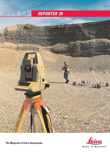
The Magazine of Leica Geosystems<br />
<strong>REPORTER</strong> <strong>39</strong><br />
MADE TO MEASURE
Customer satisfaction resulting<br />
from successful partnership<br />
Do you start at the back<br />
when reading publications?<br />
Readership surveys show<br />
that this way of getting a<br />
quick overall impression is<br />
widespread. It is not limited<br />
to those of our customers<br />
in areas deeply rooted in<br />
Islamic culture. If, by taking<br />
this course, you already<br />
have a fair idea of what is<br />
in this issue of the Reporter,<br />
then you will have grasped<br />
the breadth and importance<br />
of the "partnership"<br />
concept for Leica Geosystems.<br />
Depending on<br />
2<br />
PUBLISHING DATA<br />
Published by<br />
Leica Geosystems AG, CH-9435 Heerbrugg<br />
President & CEO: Hans Hess<br />
Editorial Office<br />
Leica Geosystems AG, CH-9435 Heerbrugg<br />
Peter Bumbacher, VP Strategic Marketing<br />
Fax: +41 71 727 46 89<br />
Internet:<br />
Peter.Bumbacher@email.leica.com<br />
Editors<br />
Peter Bumbacher, Waltraud Strobl,<br />
Fritz Staudacher<br />
Layout and Production<br />
Niklaus Frei<br />
Translation<br />
Dogrel AG, St. Margrethen<br />
Publication details<br />
Reporter is published in English, French,<br />
German, Spanish and Japanese three<br />
times a year.<br />
Reprints and translations, including<br />
excerpts, are subject fo the Editor’s prior<br />
permission in writing.<br />
Reporter is printed on chlorine-free paper<br />
made by environmentally compatible<br />
processes.<br />
© Leica Geosystems AG, Heerbrugg,<br />
July 1998, Printed in Switzerland<br />
Editorial deadline for next issue<br />
August 28, 1998<br />
circumstances, such a<br />
partnership can be<br />
all-embracing. Or it may<br />
just involve supplying a<br />
small survey instrument.<br />
In either event, customer<br />
satisfaction remains the<br />
focus of attention for Leica<br />
Geosystems.<br />
This issue includes a project<br />
which started about five<br />
years ago in America and<br />
Europe and belongs to the<br />
first type of Leica partnership.<br />
Strenuous efforts have<br />
provided Colombia with a<br />
completely new foundation<br />
for the development of its<br />
infrastructure, property<br />
boundaries and resources.<br />
In this developing Latin<br />
American country, which<br />
encompasses both primeval<br />
forests in the Amazon basin<br />
and high-altitude karst<br />
landscapes in the<br />
Cordilleras, a digital map<br />
and database have been<br />
created. Among the tools<br />
used were modern GPS,<br />
surveying, photogrammetry<br />
and land information<br />
systems from Leica. Now,<br />
with support from<br />
international organizations<br />
and with the expertise of<br />
both its own and international<br />
experts, the Colombian<br />
National Geographic<br />
Institute (IGAC) in Bogota is<br />
creating a firm foundation<br />
for the way into the next<br />
millennium. Leica and its<br />
partner companies have<br />
supplied compatible equipment<br />
covering all of the<br />
requirements in terms of<br />
instrumentation and<br />
software. We have also<br />
undertaken the training of<br />
Colombian specialists,<br />
produced the agreed end<br />
product, and established<br />
local service teams.<br />
Researchers from Swiss<br />
universities have provided<br />
the project managers with<br />
specific technical support.<br />
"Without national and<br />
international contacts, no<br />
country can cope with such<br />
challenges" was the opinion<br />
expressed by one of the<br />
specialists involved.<br />
Also included in this Reporter<br />
are various examples of<br />
quite a different kind of<br />
typical Leica partnership.<br />
For example, the young geophysics<br />
student taking his<br />
doctorate who, by creatively<br />
applying non-contact Leica<br />
surveying technology,<br />
developed a new type of<br />
georadar system for peering<br />
just below the surface of the<br />
ground. Or the co-operation<br />
with RSTC ECOMIR in<br />
compiling a modern<br />
property and environmental<br />
register. Or the flatness<br />
measurements performed by<br />
a machine-tool manufacturer<br />
whose precision work was<br />
made easier, cheaper and<br />
better by using a small<br />
"intelligent" box from Leica;<br />
the Nivel 20 and the<br />
software supplied with it.<br />
These and other examples<br />
show that for Leica a<br />
partnership is not governed<br />
by the size of the order, but<br />
by the benefits which our<br />
products bring for the<br />
customer, and by the<br />
customer satisfaction which<br />
our services accomplish.<br />
This way, commercial<br />
success comes automatically,<br />
both for our<br />
customers and for Leica.<br />
Hans Hess<br />
President & CEO<br />
Leica Geosystems<br />
In th<br />
Cover picture and page 12:<br />
Making the underground visible<br />
Page 7:<br />
More energy thanks to DISTO<br />
Page 8:<br />
Automated control for moving a<br />
bridge
is issue<br />
With the combined 3-D<br />
Georadar and Measuring<br />
Equipment SAGAS it is<br />
possible to produce<br />
subterranean maps from<br />
just below the surface<br />
and in high resolution,<br />
ten times quicker. Here<br />
the concept of the<br />
automatically tracking<br />
Leica Total Station<br />
performs a real service.<br />
The oldest hydro-electric<br />
power station in Slovakia,<br />
in the foothills of the<br />
Carpathians, needed to<br />
be renovated. The turbine<br />
room had to be measured<br />
exactly in order to increase<br />
performance at the<br />
plant. Success was<br />
achieved with the DISTO<br />
hand-held laser meter and<br />
well-proven mining<br />
surveying methods.<br />
For the European Inter City<br />
Express main rail axis,<br />
Frankfurt-Mannheim, a<br />
prefabricated underpass<br />
had to be moved 23 metres.<br />
Our solution was to use<br />
the automatic target<br />
recognizing Leica TCA 1800<br />
Total Station, together with<br />
the APS Win Software<br />
package from Leica, which<br />
were employed with great<br />
success.<br />
Page 4:<br />
A new national survey for<br />
Colombia<br />
Page 10:<br />
Precision of inclination for<br />
machines and buildings<br />
Page 14.<br />
Surveying on Television<br />
A new survey of an<br />
aspiring Latin-American<br />
developing country<br />
provided the basis for a<br />
new survey and map in<br />
the form of an interactive<br />
geographic<br />
information system.<br />
In this report one of<br />
the engineers involved<br />
describes the basic<br />
surveying work.<br />
The high precision<br />
determination of inclination<br />
and monitoring of<br />
components and<br />
buildings is very simple<br />
with the Leica NIVEL 20.<br />
Two concrete examples<br />
taken from the fields of<br />
mechanical engineering<br />
and building construction<br />
prove this once<br />
again.<br />
Leica equipment is playing an active role in the<br />
Republic of Belarus in creating new bases for<br />
surveying. On the occasion of a Leica service<br />
training course for White Russian RSTC ECOMIR<br />
specialists, a report appeared on television<br />
about the important work carried out by<br />
surveyors.<br />
Page 15:<br />
Welcome to the<br />
FIG Congress!<br />
Editorial<br />
Dear Reader,<br />
Here is issue <strong>39</strong> of our Leica<br />
customers’ magazine.<br />
It has been compiled from<br />
contributions by specialists<br />
practically involved with<br />
surveying, building and<br />
mechanical engineering.<br />
These contributions show<br />
you how your professional<br />
colleagues in other<br />
countries, on other<br />
continents and in various<br />
fields of activity, approach<br />
and accomplish their tasks.<br />
I can really imagine that<br />
you in your every-day work<br />
are also confronted with<br />
problems which are<br />
particularly difficult, and<br />
therefore especially novel<br />
and challenging as well.<br />
Would that not be worth a<br />
few lines to the editors of<br />
the Reporter together with a<br />
photograph? The Leica<br />
Reporter is the most widely<br />
read magazine in our<br />
branch in the whole world<br />
and is published in five<br />
languages to provide an<br />
international exchange of<br />
experience. A quarter of a<br />
million readers would also<br />
like to hear more about<br />
your interesting tasks and<br />
targets. Your suggestions<br />
will reach me very quickly<br />
by e-mail on:<br />
Waltraud.Strobl@email.<br />
leica.com. Many thanks,<br />
Waltraud Strobl<br />
Brand & Image Planning<br />
Manager<br />
3
A new National Survey for C<br />
by Dieter Egger*<br />
The land of Bolivar and<br />
García Márquez is presently<br />
being freshly surveyed.<br />
The new national survey is<br />
part of a Swiss-Colombian<br />
development project for<br />
the National Geographic<br />
Institute in Bogotá.<br />
Promising results are now<br />
appearing after five years of<br />
close co-operation.<br />
The Leica GPS System 300<br />
performs well anywhere, not<br />
only in regions difficult to reach<br />
where there is no visual contact.<br />
* The author is engineer ETH and works<br />
at the EPFL in Lausanne. He spent six<br />
months in Bogotá.<br />
4<br />
For Colombia, as for<br />
numerous other aspiring<br />
developing countries,<br />
region-wide, reliable maps<br />
and a recognised land<br />
registry survey form the<br />
basis for well conceived<br />
planning and secure land<br />
ownership. These are both<br />
important factors for social<br />
and economic development<br />
as well as for the stability of<br />
the nation. At the same<br />
time, Switzerland has<br />
always set international<br />
standards in the field of<br />
cartography, from the time<br />
of the Dufour map in the<br />
last century down to the<br />
present day. From this<br />
starting position, a Swiss-<br />
Colombian development<br />
project came into existence<br />
five years ago for the<br />
Colombian national geographic<br />
institute, the Instituto<br />
Geográfico Nacional<br />
Agustin Codazzi (IGAC) in<br />
Bogotá. Named after<br />
Agustin Codazzi, a seafarer<br />
and adventurer of Italian<br />
descent but who was above<br />
all Colombia’s first cartographer,<br />
the IGAC today<br />
employs about 1200 people.<br />
Their main task consists of<br />
producing all of Colombia’s<br />
topographic and thematic<br />
national maps, including<br />
compiling and managing all<br />
necessary data for them.<br />
The Modernisation Project<br />
To produce better maps<br />
more efficiently, was the<br />
aim of the large-scale and<br />
comprehensive<br />
modernisation project at the<br />
IGAC. It was, initially, partly<br />
pre-financed by a Swiss<br />
banking consortium headed<br />
by Crédit Suisse First<br />
Boston, jointly financed by<br />
the Swiss Ministry of<br />
Foreign Trade and Investment<br />
(BAWI), Development<br />
Aid Section in Bern, and<br />
planned and realised by<br />
Leica Geosystems AG in<br />
Unterentfelden, Switzerland.<br />
The traditionally<br />
employed graphic methods<br />
of classical cartography<br />
were replaced by modern<br />
digital technology. The key<br />
feature of the innovation<br />
was the introduction of a<br />
Geographic Information<br />
System (Leica INFOCAM)<br />
with a central database<br />
for the four IGAC Departemente<br />
Cartografía, Catastro,<br />
Agronomía and Geografía.<br />
Also belonging to this<br />
project, apart from the<br />
necessary training, were<br />
instruments and programs<br />
for registering, transferring<br />
and outputting of data.<br />
For example, aerial camera<br />
systems, photogrammetri-
olombia<br />
From the ground to the map and then to the land register plan with the<br />
Leica INFOCAM system.<br />
cal restitution systems,<br />
digitising stations and<br />
precision plotters. Previously<br />
on maps, despite great<br />
production expense, it was<br />
often the case that hardly a<br />
course of a river could be<br />
recognised, if it existed at<br />
all, today, detailed contours<br />
and current changes<br />
brought about by building<br />
work can be recorded and<br />
displayed in only a fraction<br />
of the time once needed.<br />
Printing plates in various<br />
scales for the same territory<br />
no longer have to be individually<br />
engraved by hand<br />
but can be produced from<br />
one and the same database.<br />
This combines various<br />
types of information and<br />
contains, for example, not<br />
only the boundaries of parcels<br />
of land but also their<br />
current use, owner etc.<br />
Once the required data is<br />
stored in the database, any<br />
random section of the land<br />
register map can be printed<br />
within two minutes (see picture).<br />
The National Survey<br />
In order to provide maps<br />
with coordinates (geographic<br />
referencing), the<br />
area to be represented must<br />
already contain some<br />
points with known<br />
coordinates which have<br />
already been surveyed. In<br />
the case of national maps,<br />
the National Survey is<br />
responsible for covering the<br />
country with a network of<br />
surveyed points (the<br />
national grid).<br />
In Colombia the IGAC had,<br />
during the Forties in<br />
co-operation with the<br />
former US Defense<br />
Mapping Agency (DMA,<br />
now the National Imagery<br />
and Mapping Agency<br />
NIMA) had already<br />
established such a nationwide<br />
network. It consists<br />
mainly of polygons which<br />
connect astronomically<br />
determined points. Because<br />
of the height of the<br />
Cordilleras, the impenetrability<br />
of the Amazon basin<br />
and the size of Colombia<br />
(about thirty times that of<br />
Switzerland) the work<br />
turned out to be extraordinarily<br />
laborious and<br />
only a heavily built-up part<br />
of the country could be<br />
surveyed. Because the<br />
methods used at that time<br />
(angle measurement with<br />
optical theodolites)<br />
necessitated visual contact<br />
between the points, these<br />
were located mostly on<br />
mountain summits where<br />
access was difficult, thus<br />
Colombian-Swiss co-operation<br />
on the new national survey of<br />
Colombia with Leica GPS.<br />
(Photos: D. Egger)<br />
increasing the cost of<br />
surveying them and<br />
reducing their usefulness.<br />
In the meantime, mankind,<br />
wind and weather have<br />
destroyed more than 50%<br />
of these points of the<br />
national grid. Additionally,<br />
in the course of modernisation,<br />
serious distortions and<br />
irregularities have come to<br />
light. Thus, the existing<br />
National Survey no longer<br />
suffices for the increased<br />
demands made by modern<br />
cartography. In 1994 as a<br />
logical consequence, the<br />
Geodesia section of the<br />
IGAC began the ambitious<br />
project of a new national<br />
survey for Colombia – with<br />
more easily accessible<br />
points, more exact<br />
coordinates and reduced<br />
costs.<br />
5
The New Base Grid<br />
As a first step in this new<br />
national survey, a new base<br />
grid was established. It<br />
consists of 60 points dispersed<br />
over the complete<br />
country (corresponding to<br />
one point for 20,000 km 2 )<br />
which are secured in the<br />
ground with massive<br />
concrete blocks. In the more<br />
densely populated areas of<br />
the Cordilleras in the northwest<br />
of the country, the grid<br />
is more closely meshed<br />
(average distance between<br />
points: 120 km) than in the<br />
south-east lowland plains of<br />
the Llanos Orientales and<br />
the Amazon basin, where<br />
the points are double this<br />
distance apart.<br />
All points were measured<br />
with the satellite-based<br />
GPS (Global Positioning<br />
System). GPS allows the<br />
position of a point to be<br />
determined exactly in<br />
relation to another, even<br />
over great distances, with<br />
the aid of satellites circling<br />
the earth. As a result, this is<br />
currently the standard<br />
method of surveying<br />
national grids. Because of<br />
the satellite connection it is<br />
also no longer necessary to<br />
have visual contact<br />
between the individual<br />
points, so these could now<br />
be located at places which<br />
were easily accessible.<br />
Nevertheless, there are still<br />
points which are only to be<br />
reached by air or following<br />
a twelve hour desert<br />
crossing. Under these<br />
conditions the field work<br />
lasted a whole four months.<br />
While the grid was planned<br />
and measured with high<br />
precision, double frequency<br />
GPS receivers by the ICAG<br />
itself, the Unité de Topométrie<br />
of the Ecole Polytechnique<br />
Fédérale in<br />
Lausanne (EPFL) attended<br />
to the actual calculations for<br />
six months, on location.<br />
For this, in the context of<br />
6<br />
adapted technology, not<br />
only technical aspects but<br />
also local characteristics,<br />
such as levels of education<br />
and knowledge of foreign<br />
languages, had to be taken<br />
into account. Thus, for<br />
example, operating instructions<br />
in English, were of no<br />
value to many IGAC<br />
engineers who did not<br />
understand this language.<br />
The grid point coordinates<br />
could be determined with<br />
an accuracy (standard<br />
deviation) of 5 cm for the<br />
location and 10 cm for the<br />
elevation, all of which were<br />
within the figures expected.<br />
At the same time the new<br />
base grid was fitted into<br />
SIRGAS, South America’s<br />
superior, wide-meshed<br />
continental grid. SIRGAS<br />
(Sistema de Referencia para<br />
America del Sur) is a<br />
modern geodetic reference<br />
system which covers the<br />
whole of South America<br />
and was successfully<br />
completed in 1997 with the<br />
participation of international<br />
experts.<br />
Owing to strong tectonic<br />
plate movements in<br />
Colombia, the grid points<br />
drift away from each other<br />
by up to 1 cm per year. A<br />
state of affairs that will have<br />
to be taken into account as<br />
the years pass. Also, early<br />
experience has already<br />
shown that the concrete<br />
slabs buried to a depth of<br />
almost a metre, are<br />
insufficient. They are being<br />
destroyed as a result of<br />
carelessness, concreted<br />
over when new houses are<br />
being built, and not least,<br />
dug up by curious people<br />
presuming that a valuable<br />
treasure lies underneath.<br />
What of the future?<br />
With the completion of the<br />
basic grid, Colombia has<br />
laid the foundation for a<br />
new national survey.<br />
Because such a grid only<br />
becomes efficient for the<br />
daily work of survey offices<br />
when a certain density of<br />
points has been reached, an<br />
increase in the 60 basic<br />
points with further subsidiary<br />
points is necessary.<br />
Added to this, all previous<br />
coordinates must be converted<br />
to the new national<br />
survey.<br />
No country can overcome<br />
such challenges without<br />
national and international<br />
contacts. The successful<br />
cooperation between the<br />
Colombian IGAC and Swiss<br />
industry, the Swiss Ministry<br />
for Foreign Trade and<br />
Investment, BAWI, and the<br />
Ecole Polytechnique<br />
Fédérale at Lausanne, EPFL,<br />
has laid the ground rules<br />
for the future of<br />
cartography in Colombia.
More energy thanks to DISTO<br />
3-D model for Ladce hydro-electric power station turbine<br />
Slovakia´s first hydroelectric<br />
power station is<br />
now sixty years old. It is<br />
situated at Ladce on the<br />
central reaches of the Vah,<br />
Slovakia´s longest river and<br />
a tributary of the Danube.<br />
In order to meet the rising<br />
demand for energy of this<br />
prospering central<br />
European region in the<br />
southern foothills of the<br />
Carpathians, near the<br />
border to the Czech<br />
Republic, an increase in the<br />
output of this old hydroelectric<br />
power station was<br />
necessary.<br />
How exactly does this<br />
turbine room appear after<br />
six decades? What structural<br />
changes are necessary<br />
to the spatial proportions<br />
and what quantities of flow,<br />
flow rates and degree of<br />
efficiency are possible by<br />
re-building, using today’s<br />
turbine technology? To<br />
determine dimensions and<br />
for the computer-aided<br />
simulation, the Leica DISTO<br />
hand-held laser meter<br />
served them admirably.<br />
The existing intake and<br />
discharge buildings were<br />
not to be altered for this<br />
increase in performance,<br />
but only the turbine room<br />
itself. The Department of<br />
Surveying at the University<br />
of Technology Bratislava<br />
was awarded the contract<br />
from the Waterpower<br />
’Station Ltd, Tencin, to<br />
ascertain the shape and<br />
volume of the existing<br />
turbine room. An optimal<br />
re-construction of the<br />
turbine was to be based on<br />
this data. The surveyor,<br />
With the Leica DISTO the<br />
dimensions of the turbine room<br />
was quickly determined by<br />
distance measurement.<br />
Isometric view of the 3-D model<br />
of the Ladce turbine<br />
Dr Alojz Kopác˘ik, employed<br />
for this demanding task in<br />
the dark turbine room, a<br />
small, hand-held and simple<br />
to operate measuring<br />
instrument, which with the<br />
most modern laser technology,<br />
determined distances<br />
to the millimetre exactly.<br />
With sections and profiles as<br />
well as a few polar points<br />
Dr. Alojz Kopác˘ik from the<br />
University of Technology<br />
Bratislava described his<br />
surveying method to the<br />
”Leica Reporter” as follows:<br />
”The objects to be<br />
measured had the form of a<br />
space spiral from above<br />
and from below that of a<br />
paraboloid, with a<br />
maximum height of eight<br />
and a half metres and a<br />
width of ten metres. The<br />
walls consisted of smoothly<br />
layered concrete which<br />
readily allowed the use of<br />
the Leica DISTO. With it a<br />
polygon with a standard<br />
deviation of ±2mm could be<br />
determined. The particular<br />
conditions such as darkness<br />
and closed spatial areas<br />
lead to the use of a measuring<br />
method with sections<br />
and profiles long familiar in<br />
mining surveying. Those<br />
portions of the turbine<br />
room which could not be<br />
determined in this way<br />
were recorded in the form<br />
of sets of polar points.”<br />
Shape and volumes for the<br />
3-D model<br />
Based on this grid measurement<br />
data, a 3-D model was<br />
compiled on a PC with a<br />
Pentium processor and CAD<br />
software. The surfaces were<br />
formed as B spline surfaces<br />
with a tolerance of ten<br />
millimetres, which, for the<br />
surface points, represents<br />
an accuracy of 10-20 millimetres.<br />
Versatile calculations and<br />
views<br />
This model was used in<br />
various ways for calculating<br />
and 3-D visualising. Part of<br />
the available data set is, for<br />
example:<br />
- a set of the spatial coordinates<br />
of all measured<br />
points,<br />
- a set of the sections and<br />
profiles,<br />
- the digital shape of the<br />
three dimensional model<br />
with B spline surface<br />
covering,<br />
- the views of the model<br />
from different directions.<br />
As a result of this information,<br />
the optimal shape for<br />
the new turbine room could<br />
be determined exactly,<br />
quickly and reliably. The<br />
environmentally friendly<br />
“White Force” of the River<br />
Vah will be better used with<br />
a considerably degree of<br />
efficiency, without changes<br />
having to be made to the<br />
landscape.<br />
- Stf -<br />
7
Automated control when moving<br />
a bridge<br />
A Leica TCA 1800 automatic<br />
target recognizing precision<br />
total station, controlled<br />
by the Leica APS Win<br />
Software, was in use when<br />
a bridge was moved by<br />
23 metres below the Inter<br />
City Express main rail axis<br />
Mannheim-Frankfurt. This<br />
work on the Mannheim-<br />
Blumenau railway line was<br />
carried out by the<br />
Mannheim office of Bilfinger<br />
+ Berger Bauaktiengesellschaft.<br />
The surveyor<br />
responsible for the<br />
measured control of the<br />
undertaking H. P. Echsle,<br />
describes this operation for<br />
our readers.<br />
Improvement of the Inter City<br />
Express high speed railway<br />
line<br />
As part of the improvements<br />
to the high speed<br />
railway line on the western<br />
double track Inter City<br />
Express link Mannheim –<br />
Frankfurt am Main the<br />
barriered level crossing at<br />
ground level in Mannheim-<br />
Blumenau had to be<br />
extended to become a road<br />
underpass in a groundwater<br />
carrying area. Because this<br />
line is one of the German<br />
Federal Railway Ltd main<br />
north-south routes, rail traffic<br />
could only be minimally<br />
restricted (slow speed line<br />
with a maximum of 70<br />
km/h). For this reason the<br />
construction was built in the<br />
form of a sliding frame in a<br />
ditch directly next to the<br />
tracks.<br />
2,400 Tons Heavy and<br />
18 Metres Wide<br />
This sliding frame building<br />
element was 18 metres<br />
wide, 13 metres long,<br />
8 metres high and weighed<br />
2,400 tons. With computercontrolled<br />
hydraulic presses<br />
having a force of 3,500 tons,<br />
it was pushed 23 metres<br />
8<br />
Leica miniature prisms were located at all important surveying<br />
points. They are clearly seen here next to the red clamps.<br />
Photo. Gudrun Keese<br />
under the tracks until it<br />
reached its final position.<br />
To achieved this, from the<br />
surveying point of view,<br />
there were two problems to<br />
solve:<br />
- monitoring the element<br />
during sliding,<br />
- monitoring the tracks.<br />
Measuring points signalled<br />
with Leica miniature prisms<br />
For this purpose three<br />
groups of points were<br />
established:<br />
1.Five reference points for<br />
location control (Ref 1-5),<br />
2.Seven sliding frame<br />
measuring points<br />
(VR 10-16),<br />
Here the Leica TCA 1800<br />
automatic target recognizing<br />
total station is being installed on<br />
the surveying column at the site.<br />
Computer-controlled and<br />
recording to the APS Win<br />
measuring programs, it took aim<br />
at the miniature prisms without<br />
the presence of an observer and<br />
determined their current<br />
position with great accuracy.<br />
Photo: Gudrun Keese<br />
3.Twenty deformation<br />
measuring points on the<br />
provisional bridge for<br />
the tracks (D 101-110,<br />
D 201-210).<br />
Leica miniature prisms<br />
were fixed to all these<br />
measuring points. The automatic<br />
target recognizing<br />
Leica TCA 1800 total station
which was installed on a<br />
surveying column,<br />
re-determined the measuring<br />
point coordinates<br />
during the sliding process<br />
after each 20-40 centimetres<br />
of the slide path.<br />
This is how the bridge<br />
re-location measuring<br />
arrangements appeared.<br />
© Echsle/Bilfinger + Berger<br />
Immediate automatically<br />
balanced coordinate values<br />
The re-measuring of the<br />
sliding process, which was<br />
required, was started by a<br />
single operator between<br />
halts and pauses between<br />
trains. The Leica APS Win<br />
software controlled the<br />
measuring procedure<br />
completely automatically.<br />
Balanced coordinate values<br />
were available immediately,<br />
The deviation at each measuring point was recorded and graphically<br />
presented at regular intervals.<br />
The sliding frame element was prefabricated in a ditch 23 metres<br />
away. Photo: Gudrun Keese<br />
and with their help, the<br />
movements of the sliding<br />
frame were ascertained<br />
according to position and<br />
height.<br />
Controlling the sliding<br />
frame was consequently no<br />
problem.<br />
The final position was<br />
reached with a traverse<br />
error of +2 mm on the front<br />
edge of the frame and +6<br />
mm at the rear. A final<br />
deviation of ±25 mm<br />
resulted for the height of<br />
the frame caused by the<br />
slide path.<br />
Track settling diagrams with<br />
MS Excel<br />
For visualising the<br />
deformation in the tracks,<br />
settling diagrams were<br />
drawn up with the help of<br />
the MS Excel spread sheet<br />
program. The data transfer<br />
from Leica APS Win was<br />
effected with a self-written<br />
program. With the help of<br />
this settling diagrams, it<br />
was possible to quickly<br />
remedy the deformation in<br />
the tracks.<br />
The combination of the<br />
Leica APS Win Software<br />
with the automatic target<br />
recognizing Leica TCA 1800<br />
precision total station<br />
allows us to acquire and<br />
visualise large-scale<br />
building movements<br />
quickly and accurately.<br />
9
Measuring even surfaces on<br />
high precision components<br />
The Leica NIVEL 20 in the production of measuring machines and machine tools<br />
The Oelze Präzisions-<br />
Messzeugfabrik GmbH in<br />
Aschaffenburg, Germany,<br />
is an accredited German<br />
Calibration Service (DKD)<br />
calibration centre for<br />
quantities to be measured<br />
for straightness, evenness<br />
and squareness. When<br />
measuring for straightness<br />
and evenness, the NIVEL 20<br />
is the means of measuring<br />
at Oelze approved by the<br />
German Federal Physical<br />
Technical Institute (PTB).<br />
Apart from its standard products,<br />
the innovative Oelze<br />
family company, now into<br />
its third generation, also<br />
manufactures basic<br />
modules for high precision<br />
measuring machines and<br />
machine tools. For some<br />
time Oelze have been<br />
working with the NIVEL 20<br />
inclination sensor from<br />
Leica and have gained at lot<br />
of useful experience with it.<br />
10<br />
The base frame or bed of<br />
such a machine is a loadbearing<br />
component. Fixed<br />
to it are feeding elements,<br />
guides and drives etc. The<br />
bed is therefore in the<br />
direction of force lines and<br />
it deforms as a result of the<br />
forces which are exerted on<br />
it.<br />
In order to measure and<br />
process products in the µm<br />
range, one of the conditions<br />
required is a statically,<br />
dynamically and thermally<br />
stable construction for the<br />
base frame. Here, the<br />
designer with a suitable<br />
choice in raw materials and<br />
a construction which takes<br />
those materials into<br />
account, can provide the<br />
basis for a successful<br />
machine. The Oelze<br />
products which are<br />
specifically designed for<br />
customers, use primarily<br />
granite as the material.<br />
Dr T Barth from Oelze<br />
explains the procedure as<br />
follows: ”In order to manufacture<br />
the component part<br />
of a precision machine from<br />
a natural product like stone,<br />
the functional surfaces are<br />
highly accurately ground in<br />
our factory, that is in the µm<br />
range, and are then lapped<br />
by hand. Apart from the<br />
right personnel and stable<br />
climatic conditions, a<br />
further pre-condition is the<br />
use of a suitable means of<br />
measuring”.<br />
Exacting straightness and<br />
evenness measuring<br />
For the actual measuring<br />
for straightness and<br />
evenness, the surface to be<br />
measured is provided with<br />
a grid. Along this network<br />
the transducer is moved in<br />
short stages. In doing this<br />
the inclination of the<br />
transducer is registered at<br />
each measuring point and<br />
from this data, changes in<br />
height are calculated. The<br />
individual changes in height<br />
are linked by the software<br />
and the straightness<br />
and evenness profile is<br />
calculated.<br />
Measuring machine for<br />
measuring rotationally<br />
symmetrical components.<br />
Required evenness for the<br />
guide surface is 0.005 mm.<br />
During measuring for<br />
straightness, the inclination<br />
is registered in one<br />
direction, while during<br />
measuring for evenness the<br />
inclinations have to be<br />
registered in two mutually<br />
perpendicular directions.<br />
The means of measuring<br />
employed by Oelze must<br />
have the following<br />
characteristics:<br />
- simple and reliable<br />
operation of both the<br />
transducer and the<br />
software,<br />
- reproducibility of the<br />
results of measuring, that<br />
is, long term stability,<br />
operator independence,<br />
- suitable resolution,<br />
- low dead weight,<br />
- rigid, low-vibration<br />
construction,<br />
- good price / performance<br />
ratio.<br />
As Dr T Bart from Oelze<br />
said: ”From our point of<br />
view the NIVEL 20<br />
measuring instrument<br />
offered by Leica fulfilled<br />
these requirements. As<br />
compared with the means<br />
of measuring previously<br />
known to us, the system<br />
stands out particularly in<br />
the simultaneous<br />
registering of inclinations in<br />
two mutually perpendicular<br />
(bi-directional) directions.<br />
Apart from the slight<br />
possibility of making a<br />
mistake (each movement of<br />
a measuring sensor brings
about a possibility for<br />
making an error) the result<br />
is that the time taken for<br />
measuring is minimised.<br />
The saving in time with<br />
more than 100 measuring<br />
points can amount to<br />
quarter of an hour.<br />
Taking into account that the<br />
manufacture of precision<br />
surfaces is an iterative<br />
process, that is, repetition<br />
of measuring – processing –<br />
measuring etc., the costeffectiveness<br />
of the system<br />
can be proved fairly<br />
quickly”.<br />
Software now runs under<br />
MS Windows<br />
Unlike the original versions,<br />
the NIVEL 20 software has<br />
been noticeably further<br />
developed. It now runs<br />
under Windows and therefore<br />
enables the complete<br />
Microsoft Windows world<br />
to be used. By this means<br />
the results (either as a table<br />
or as a graphic) can be<br />
directly inserted in a text or<br />
test certificate etc.<br />
Assembly equipment<br />
for printing machines.<br />
Required evenness<br />
A close look directly below<br />
the Earth’s surface<br />
Frank Lehmann, a graduate<br />
physicist at the Technical<br />
University in Zurich (ETHZ),<br />
compiled high resolution<br />
3-D maps of the subsoil<br />
down to a maximum depth<br />
of twenty metres, ten times<br />
quicker than previously<br />
possible, using a developed<br />
georadar and surveying<br />
system. In his SAGAS<br />
system, the research<br />
student studying for his<br />
doctorate at the ETH<br />
Institute for Geophysics<br />
combined an electromagnetic<br />
georadar unit with<br />
an automatic precision total<br />
station able to continuously<br />
determine position and<br />
height.<br />
All geological and geographical<br />
data is collected in<br />
real-time online via glass<br />
fibre cables by a laptop PC<br />
using specially developed<br />
software, and then linked<br />
and processed. Thus the<br />
geophysicist and other interested<br />
specialists received<br />
the 3-D subterranean map<br />
from just below the surface<br />
of the ground, straight after<br />
completing the field measurements!<br />
This ”Semi-Automated Georadar<br />
Acquisition System”<br />
SAGAS, enables a single<br />
person to gain high<br />
resolution insights into the<br />
upper earth layers and<br />
simultaneously to determine<br />
three-dimensionally this<br />
measuring data in real-time<br />
exact to the centimetre.<br />
In a comprehensive practical<br />
test in a geologically welldocumented<br />
former ice age<br />
river bed landscape not far<br />
from the Rhine on the<br />
Swiss-German border, the<br />
subsoil of the 625 square<br />
metre large test area could<br />
be three dimensionally<br />
recorded about ten times<br />
quicker than with the static<br />
”stop-and-go” measuring<br />
method used up to now, and<br />
in considerably more detail.<br />
12<br />
Spatial geologic and<br />
surveying data provided<br />
together and continuously<br />
The normal commercially<br />
available georadar antennas<br />
of the SAGAS system (transmitter<br />
and receiver) work to<br />
achieve a high resolution<br />
with frequencies between<br />
25 to 1000 MHz. They are<br />
fixed in a measuring carriage<br />
above the ground. The<br />
appearance of this little<br />
carriage reminds the<br />
observer on first sight of the<br />
LEM-Moon Rover, but it is<br />
considerably more simply<br />
constructed from rods and<br />
connecting elements which<br />
are all plugged together, are<br />
free of electro-magnetic<br />
influences and can also be<br />
dismantled to save space<br />
when transported by road,<br />
vehicle or aeroplane. The<br />
highest point on the measuring<br />
carriage is a glass<br />
reflector prism, which also<br />
does not disturb the georadar<br />
signals and is located<br />
exactly in the middle of the<br />
Frank Lehmann has located here<br />
with his georadar system, a<br />
scour pool at which during a<br />
certain post ice age period the<br />
courses of two rivers met. The<br />
present remaining river course<br />
of the Rhine lies a few hundred<br />
metres further south (to be seen<br />
in the background of the picture)<br />
and is about sixty metres deeper.<br />
The extensive test area was<br />
within a present-day gravel pit<br />
near Hüntwangen in the Swiss<br />
canton of Schaffhausen.<br />
The data is collected in a laptop computer via glass fibre cables. The geophysicist monitors the<br />
acquisition of data on the screen.<br />
radar antennas. It is<br />
continuously targeted by a<br />
Leica TCA 1800 automatic<br />
target recognizing precision<br />
total staion. For this, the<br />
measuring instrument is<br />
mounted on a tripod at the<br />
start of the field work,<br />
aimed once at the prism<br />
with the telescope and then<br />
switched to ”Measure”.<br />
From this moment on, the<br />
Leica TCA 1800 always<br />
holds the measuring<br />
carriage prism in focus<br />
automatically.
The total station constantly<br />
determines the horizontal<br />
and vertical angle to the<br />
prism as well as its current<br />
distance from continually<br />
running measuring sequences,<br />
from electro-optical<br />
angle measuring and<br />
electronic infra red laser<br />
distance measuring. This<br />
data is immediately computed<br />
by the Leica TCA 1800<br />
into position and height<br />
coordinates of the prism or<br />
of the georadar centre<br />
point, exact to the centimetre.<br />
At the same time,<br />
where the terrain has an<br />
inclination, the vertical<br />
variations of the prism at<br />
the point of the measuring<br />
carriage are also mathematically<br />
compensated by<br />
the SAGAS software. The<br />
georadar equipment and<br />
measuring station are<br />
directly connected to the<br />
geophysicist’s laptop<br />
computer by thin glass fibre<br />
cables and he draws the<br />
measuring carriage along<br />
the desired profiled lines<br />
with the help of the realtime<br />
position data.<br />
3-D evaluation directly in<br />
the field<br />
The SAGAS software<br />
continuously integrates all<br />
reflection and coordinate<br />
data and presents it to the<br />
In this interlocking georadar<br />
picture sections and the equal<br />
time section, the geophysicist<br />
recognises on location at once<br />
the water table (green line) and<br />
reflections from objects transmitted<br />
from above the surface of<br />
the ground (yellow lines) thanks<br />
to the 3-D presentation. SP1 and<br />
SP2 mark the lower boundary<br />
between two erosion troughs.<br />
© Frank Lehmann/ETH.<br />
geophysicist in the desired<br />
form directly in the field.<br />
Special features of the<br />
territory investigated and its<br />
surroundings, such as, for<br />
example, the ground water<br />
table and reflections from<br />
buildings above ground<br />
level which are also represented<br />
in the georadar data,<br />
can in this way be explained<br />
more quickly and if required,<br />
filtered out. Naturally, these<br />
comprehensive and threedimensionallyhigh-resolution<br />
data sets can be used in<br />
the office later for various<br />
purposes including further<br />
and more detailed study.<br />
In comparison with the static<br />
methods, appreciably finer<br />
analyses are possible in a<br />
distinctly shorter period of<br />
time.<br />
At least ten times quicker<br />
than previously<br />
Frank Lehmann together<br />
with Alan G Green has<br />
described this system in<br />
detail in a paper entitled<br />
”Semi-automated georadar<br />
data acquisition in three<br />
dimensions”.<br />
It is accessible by e-mail<br />
(frankl@augias.ig.erdw.ethz<br />
.ch) to anyone who is<br />
interested. As Frank<br />
Lehmann says: ”With this<br />
method a variety of<br />
problems affecting the<br />
subsoil and of concern in<br />
geology, engineering<br />
science and archaeology<br />
can be solved more simply<br />
and more exactly than<br />
previously. During our<br />
study we pulled our measu-<br />
Six equal time sections of the scour pool. Its boundaries are<br />
shown here marked with green lines.<br />
© Frank Lehmann/ETH<br />
The Leica TCA 1800 total station<br />
tracked the measuring carriage<br />
continuously and provided the<br />
geophysicist with his actual<br />
position by way of a graphic<br />
display in real-time on the<br />
laptop screen. Thus he can also<br />
always keep to the ideal line for<br />
his current project and the<br />
system trigger the radar measurements<br />
at the correct intervals.<br />
The geophysicist is carrying the<br />
georadar control unit on his<br />
back.<br />
ring carriage at the rate of<br />
only 0.3 m/s although as far<br />
as the measuring system<br />
itself was concerned, even<br />
3 m/s would have been<br />
possible for providing<br />
sufficient accuracy. Even<br />
with our gentle speed, we<br />
obtained our results ten<br />
times more quickly when<br />
compared with the methods<br />
available up till now. The<br />
data processing was also<br />
carried out so quickly that<br />
we could easily display, on<br />
our laptop screen, threedimensional<br />
profile sections<br />
in various directions and<br />
also sections covering periods<br />
from the past, while still<br />
in the gravel pit ”.<br />
- Stf -<br />
Here SAGAS presents a section of the scour pool<br />
of the two water courses from the complete picture<br />
in raised, three-dimensional volume presentation.<br />
© Frank Lehmann/ETH<br />
13
Surveying on Television<br />
The general public in Belarus is informed about surveying projects.<br />
Cameraman and TV reporter are interested in the work of surveying<br />
specialists. Centre picture: Dr Alexander A. Kovalyov, Director of<br />
ECOMIR (left) and Leica service training engineer Anton Schneider<br />
being interviewed.<br />
Next<br />
Olympic Games<br />
in view<br />
Australian sports fans are<br />
already preparing for the<br />
biggest sporting event of<br />
the turn of the millennium.<br />
14<br />
In Sydney, building work<br />
for a new Olympic stadium<br />
is beginning. One of the<br />
building contractors<br />
principally engaged has just<br />
acquired two Leica TCA<br />
1100 total stations specially<br />
to cope with this mighty<br />
and demanding project.<br />
As with the “Stade de<br />
France” which matched<br />
Olympic proportions<br />
(see Reporter 38), just as<br />
the football World Cup<br />
Championship comes to an<br />
end, this stadium will bear<br />
the good measure of Leica.<br />
In the Nineties, in the field<br />
of surveying and land<br />
registration, the Republic of<br />
Belarus took a mighty step<br />
forward into the future.<br />
Nestling between Poland in<br />
the west, Ukraine in the<br />
east and Lithuania and<br />
Latvia in the north, White<br />
Russia has become an<br />
important hub for northeast<br />
Europe.<br />
With the creation of a new<br />
basis for private property,<br />
projects involving traffic<br />
infrastructure and documents<br />
for environmental<br />
protection in the form of<br />
digital maps and plans, the<br />
RSTC ECOMIR Center<br />
associated with the Belarus<br />
Academy of Sciences has<br />
performed the pioneering<br />
work. The most important<br />
work was carried out with<br />
Leica surveying equipment.<br />
On the occasion of a service<br />
Maritime safety<br />
with Leica<br />
Leica was awarded the<br />
contract worth more than<br />
$US 1.79 million to erect a<br />
DGPS transmitting station in<br />
China.<br />
The PRC Maritime Safety<br />
Administration has awarded<br />
Leica the contract for<br />
erecting a DGPS reference<br />
beacon station. The contract<br />
also includes DGPS and<br />
surveying instruments<br />
(MX9400, RTK System,<br />
TPS 1000, NA3003 digital<br />
level) for hydrographic and<br />
land surveying tasks, as well<br />
as DGPS navigational instruments<br />
(MX GPS Navigator)<br />
for their marine engineering.<br />
training course conducted<br />
by Leica specialists directly<br />
in Minsk for members of<br />
this Center, a Belarus<br />
television team portrayed<br />
the ECOMIR Center and<br />
its important tasks in<br />
developing the country.<br />
Reporter readers will also<br />
learn more about this from<br />
the pen of one of the<br />
specialists involved, in the<br />
next issue.<br />
- Stf -<br />
This is the second DGPS<br />
station with surveying equipment<br />
which the Peoples’<br />
Republic of China has<br />
ordered from Leica, following<br />
the positive experience<br />
gained on completing a first<br />
contract. As hardly any other<br />
manufacturer operating in<br />
the world market, Leica can<br />
deliver this equipment of<br />
high quality and reliability<br />
from a single source and<br />
offer the Chinese MSA a<br />
complete solution of marine<br />
navigation and for all<br />
hydrographic surveying and<br />
land survey problems.
FIG in Brighton<br />
Brighton, THE coastal resort,<br />
this year accommodates in the<br />
Brighton Metropole Hotel the<br />
international FIG congress and<br />
exhibition. Brighton, one of the<br />
most attractive towns on<br />
Britain’s south coast, also offers<br />
a considerable choice of<br />
opportunities for entertainment<br />
and relaxation. It is only a few<br />
paces from the exhibition hall<br />
to the promenade with its<br />
innumerable small cafes, bars<br />
and restaurants, and the Palace<br />
Pier with its traditional and<br />
modern beach amusements:<br />
exactly the right surroundings<br />
after a day richly loaded with<br />
congress topics and exhibition<br />
visits. This year’s FIG congress<br />
subject is “Developing the<br />
Profession in a Developing<br />
World” clearly indicates<br />
without the necessity for<br />
further explanation what is<br />
waiting there for you. Not only<br />
international businesses and<br />
organisations are on the list of<br />
exhibitors, but also local<br />
surveying and mapping firms<br />
and institutions, all of which<br />
promises to be an interesting<br />
mixture!<br />
Leica Geosystems can be found<br />
at Stand 14 in Hall 3. If it should<br />
prove impossible for you to<br />
meet us there, you will get the<br />
opportunity of receiving<br />
information in the next issue of<br />
the Reporter or from our web<br />
site in the Internet.<br />
Waltraud Strobl<br />
15
30 40 50<br />
So many nations have something keeping them apart. For the people of<br />
Sweden and Denmark, it’s the Øresund.<br />
Extreme measures by Leica<br />
“Leica GPS systems are bringing two countries together.”<br />
A 16km stretch of turbulent, icy water. But with the help of Leica’s<br />
GPS, they’re getting over it. Aage Hansen, Project Coordinator at Øre-<br />
sundkonsortium, is overseeing GEO and GIS technology for<br />
The Øresund Link. A vast structure planned to join the countries.<br />
“ Before crossing the Øresund, there were bigger problems to<br />
negotiate. Strong frequency limitations were giving us trouble. And<br />
a project of this scale must have reliable information. Leica had the inno-<br />
vative solution. Using GPS technology, a system with six frequencies<br />
Call Leica Geosystems +1 800 367 9453 (Americas) +65 568 9845 (Asia) or www.leica-geosystems.com/ads<br />
was established. Supplying real time GPS data over the entire project<br />
area makes the project easy to coordinate and maintain And it ensures.<br />
all our contractors are always given the correct data ,<br />
which saves everyone time and money.”<br />
For Aage Hansen, choosing Leica is already paying off, with the project<br />
making impressive progress. And now you too can benefit from the expe-<br />
rience gained in helping build The Øresund Link. To find out how, call +44<br />
181 256 9030 (Europe) or your<br />
local representative, and let<br />
Leica Geosystems help you and<br />
your projects go further.<br />
M A D E T O M E A S U R E