Investigation of Two-Photon Laser-Induced Fluorescence Detection ...
Investigation of Two-Photon Laser-Induced Fluorescence Detection ...
Investigation of Two-Photon Laser-Induced Fluorescence Detection ...

Create successful ePaper yourself
Turn your PDF publications into a flip-book with our unique Google optimized e-Paper software.
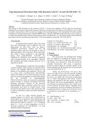
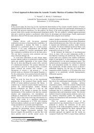
C 2 interferences<br />
(c 1 Π g – b 1 Π u)<br />
(d 3 Π g – a 3 Π u)<br />
-7 -6 -5 -4 -3 -2 -1 0 1 2 3 4 5 6 7<br />
Distance (mm)<br />
400<br />
450<br />
500<br />
550<br />
600<br />
650<br />
Wavelength (nm)<br />
Figure 6. A CO fluorescence spectrum from a<br />
methane/air (φ=1.5) burner is shown above. The C 2<br />
lines around 474 nm and 520 nm are visible.<br />
Engine measurements<br />
The measurements in the cell and the premixed<br />
flame were followed by measurements in a small<br />
single-cylinder four-stroke Briggs & Stratton engine<br />
[23]. The engine featured a side-valve design with the<br />
spark plug located above the exhaust valve. The<br />
original crankcase, cylinder liner and piston remained<br />
unaltered, while the cylinder head was modified to<br />
allow for optical access to the combustion chamber.<br />
Three windows were mounted in the cylinder head<br />
for this purpose. <strong>Two</strong> vertical windows, one on the<br />
side <strong>of</strong> the combustion chamber, made it possible to<br />
have a horizontal laser sheet passing through it. The<br />
induced fluorescence was imaged through a third<br />
window mounted horizontally above the two valves.<br />
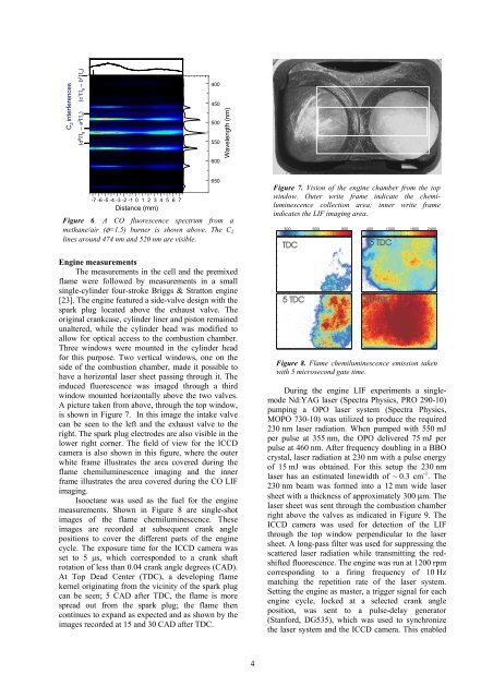
A picture taken from above, through the top window,<br />
is shown in Figure 7. In this image the intake valve<br />
can be seen to the left and the exhaust valve to the<br />
right. The spark plug electrodes are also visible in the<br />
lower right corner. The field <strong>of</strong> view for the ICCD<br />
camera is also shown in this figure, where the outer<br />
white frame illustrates the area covered during the<br />
flame chemiluminescence imaging and the inner<br />
frame illustrates the area covered during the CO LIF<br />
imaging.<br />
Isooctane was used as the fuel for the engine<br />
measurements. Shown in Figure 8 are single-shot<br />
images <strong>of</strong> the flame chemiluminescence. These<br />
images are recorded at subsequent crank angle<br />
positions to cover the different parts <strong>of</strong> the engine<br />
cycle. The exposure time for the ICCD camera was<br />
set to 5 µs, which corresponded to a crank shaft<br />
rotation <strong>of</strong> less than 0.04 crank angle degrees (CAD).<br />
At Top Dead Center (TDC), a developing flame<br />
kernel originating from the vicinity <strong>of</strong> the spark plug<br />
can be seen; 5 CAD after TDC, the flame is more<br />
spread out from the spark plug; the flame then<br />
continues to expand as expected and as shown by the<br />
images recorded at 15 and 30 CAD after TDC.<br />
4<br />
Figure 7. Vision <strong>of</strong> the engine chamber from the top<br />
window. Outer write frame indicate the chemiluminescence<br />
collection area; inner write frame<br />
indicates the LIF imaging area.<br />
300 600 900 400 1000 1800 2400<br />
TDC<br />
15 TDC<br />
5 TDC 30 TDC<br />
Figure 8. Flame chemiluminescence emission taken<br />
with 5 microsecond gate time.<br />
During the engine LIF experiments a singlemode<br />
Nd:YAG laser (Spectra Physics, PRO 290-10)<br />
pumping a OPO laser system (Spectra Physics,<br />
MOPO 730-10) was utilized to produce the required<br />
230 nm laser radiation. When pumped with 550 mJ<br />
per pulse at 355 nm, the OPO delivered 75 mJ per<br />
pulse at 460 nm. After frequency doubling in a BBO<br />
crystal, laser radiation at 230 nm with a pulse energy<br />
<strong>of</strong> 15 mJ was obtained. For this setup the 230 nm<br />
laser has an estimated linewidth <strong>of</strong> ~ 0.3 cm -1 . The<br />
230 nm beam was formed into a 12 mm wide laser<br />
sheet with a thickness <strong>of</strong> approximately 300 µm. The<br />
laser sheet was sent through the combustion chamber<br />
right above the valves as indicated in Figure 9. The<br />
ICCD camera was used for detection <strong>of</strong> the LIF<br />
through the top window perpendicular to the laser<br />
sheet. A long-pass filter was used for suppressing the<br />
scattered laser radiation while transmitting the redshifted<br />
fluorescence. The engine was run at 1200 rpm<br />
corresponding to a firing frequency <strong>of</strong> 10 Hz<br />
matching the repetition rate <strong>of</strong> the laser system.<br />
Setting the engine as master, a trigger signal for each<br />
engine cycle, locked at a selected crank angle<br />
position, was sent to a pulse-delay generator<br />
(Stanford, DG535), which was used to synchronize<br />
the laser system and the ICCD camera. This enabled