A guaranteed obstacle avoidance guidance system: The safe ...
A guaranteed obstacle avoidance guidance system: The safe ...
A guaranteed obstacle avoidance guidance system: The safe ...

Create successful ePaper yourself
Turn your PDF publications into a flip-book with our unique Google optimized e-Paper software.
hal-00733826, version 1 - 19 Sep 2012<br />
Auton Robot (2012) 32:177–187<br />
DOI 10.1007/s10514-011-9269-5<br />
A <strong>guaranteed</strong> <strong>obstacle</strong> <strong>avoidance</strong> <strong>guidance</strong> <strong>system</strong><br />
<strong>The</strong> <strong>safe</strong> maneuvering zone<br />
Lionel Lapierre · Rene Zapata<br />
Received: 13 January 2011 / Accepted: 2 December 2011 / Published online: 4 January 2012<br />
© Springer Science+Business Media, LLC 2012<br />
Abstract This paper presents a practical solution to the<br />
<strong>guidance</strong> of a unicycle type robot, including path following,<br />
<strong>obstacle</strong> <strong>avoidance</strong> and the respect of wheeled actuation<br />
saturation constraint, without planning procedure. <strong>The</strong>se results<br />
are based on an extension of previous results on path<br />
following control including actuation saturation constraints.<br />
New solution for <strong>obstacle</strong> <strong>avoidance</strong>, with <strong>guaranteed</strong> performance,<br />
is proposed.<br />
Keywords Path following · Obstacle <strong>avoidance</strong> ·<br />
Saturation constraints<br />
1 Introduction<br />
1.1 Context and objectives<br />
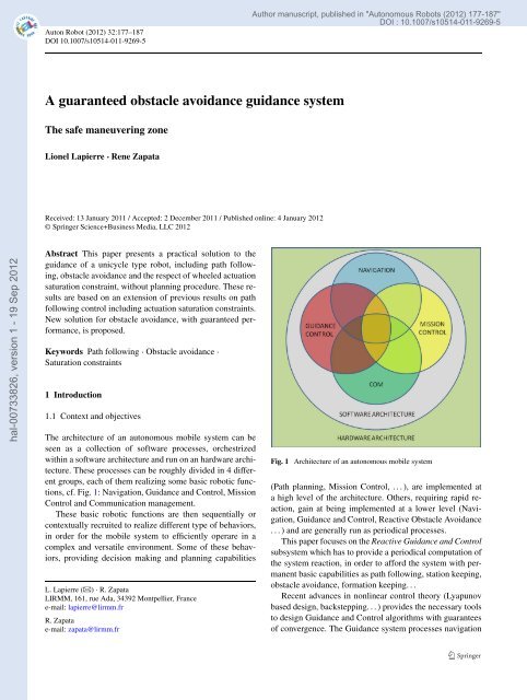
<strong>The</strong> architecture of an autonomous mobile <strong>system</strong> can be<br />
seen as a collection of software processes, orchestrized<br />
within a software architecture and run on an hardware architecture.<br />
<strong>The</strong>se processes can be roughly divided in 4 different<br />
groups, each of them realizing some basic robotic functions,<br />
cf. Fig. 1: Navigation, Guidance and Control, Mission<br />
Control and Communication management.<br />
<strong>The</strong>se basic robotic functions are then sequentially or<br />
contextually recruited to realize different type of behaviors,<br />
in order for the mobile <strong>system</strong> to efficiently operare in a<br />
complex and versatile environment. Some of these behaviors,<br />
providing decision making and planning capabilities<br />
L. Lapierre () · R. Zapata<br />
LIRMM, 161, rue Ada, 34392 Montpellier, France<br />
e-mail: lapierre@lirmm.fr<br />
R. Zapata<br />
e-mail: zapata@lirmm.fr<br />
Author manuscript, published in "Autonomous Robots (2012) 177-187"<br />
DOI : 10.1007/s10514-011-9269-5<br />
Fig. 1 Architecture of an autonomous mobile <strong>system</strong><br />
(Path planning, Mission Control, ...), are implemented at<br />
a high level of the architecture. Others, requiring rapid reaction,<br />
gain at being implemented at a lower level (Navigation,<br />
Guidance and Control, Reactive Obstacle Avoidance<br />
...)andaregenerally run as periodical processes.<br />
This paper focuses on the Reactive Guidance and Control<br />
sub<strong>system</strong> which has to provide a periodical computation of<br />
the <strong>system</strong> reaction, in order to afford the <strong>system</strong> with permanent<br />
basic capabilities as path following, station keeping,<br />
<strong>obstacle</strong> <strong>avoidance</strong>, formation keeping. . .<br />
Recent advances in nonlinear control theory (Lyapunov<br />
based design, backstepping...)providesthenecessary tools<br />
to design Guidance and Control algorithms with guarantees<br />
of convergence. <strong>The</strong> Guidance <strong>system</strong> processes navigation
hal-00733826, version 1 - 19 Sep 2012<br />
178 Auton Robot (2012) 32:177–187<br />
data and path parameters in order to provide an achievable<br />
reference to the control <strong>system</strong> that drives the actuation. In<br />
this context, a <strong>guidance</strong> <strong>system</strong> should drive the <strong>system</strong> towards<br />
its current objective, while respecting the actuation<br />
saturation constraint, and providing a reference compatible<br />
with the <strong>system</strong> dynamics. This last point is not considered<br />
in this paper, and could be tackled using backstepping techniques<br />
(Krstićetal.1995), assuming that the reference is differentiable,<br />
and is Globally, Uniformly and Asymptotically<br />
Convergent (GUAC). Moreover, this property warrants that,<br />
in the absence of sensor noise or modeling error, the control<br />
<strong>system</strong> will constantly and perfectly drive the <strong>system</strong> toward<br />
its objective. <strong>The</strong> effect of sensor noise will be to degrade<br />
the convergence property, down to a practical convergence,<br />
as far as the sensor suite and the navigation <strong>system</strong> afford an<br />
evaluation of the <strong>system</strong> states with a <strong>guaranteed</strong> and computable<br />
upper bound on the estimation error.<br />
<strong>The</strong> objective of this paper is to propose a low-level reactive<br />
Guidance and Control sub<strong>system</strong> that aims at preserving<br />
the convergence properties as the following functions are<br />
considered in the algorithm:<br />
– Path following<br />
– Actuation saturation constraint<br />
– Obstacle <strong>avoidance</strong><br />
In Lapierre et al. (2006), we proposed a solution for<br />
path following control design of a unicycle type robot, that<br />
formally exhibits Global Uniform Asymptotic convergence<br />
(GUAC) property. In Lapierre and Indiverri (2007) thissolution<br />
is extended to consider velocity saturation constraints<br />
of the actuators, while preserving the GUAC property. <strong>The</strong><br />
solution proposed here, includes <strong>obstacle</strong> <strong>avoidance</strong> capability,<br />
combined with path following behavior. <strong>The</strong> objective is<br />
to propose a global solution to this problem, which formally<br />
guarantees:<br />
– a Global Uniform Asymptotic Convergence of the robot<br />
to the path, when there is no <strong>obstacle</strong>, and<br />
– that a minimum distance to the <strong>obstacle</strong> is respected, explicitly<br />
considering actuator velocity constraints, and<br />
– that the <strong>system</strong> will retrieve its path following behavior<br />
when the obstruction has been avoided.<br />
In the sequel, the Navigation <strong>system</strong> is considered as<br />
ideal and provides a perfect estimation of the <strong>system</strong> states,<br />
and the <strong>system</strong> models are considered as perfectly known.<br />
1.2 Some bibliographic elements<br />
1.2.1 Path-following<br />
Motion control of autonomous vehicles has received considerable<br />
attention during the last few years. <strong>The</strong> solutions<br />
proposed in the literature can be roughly classified in three<br />
groups:<br />
– point stabilization: the goal is to stabilize the vehicle at a<br />
given point, with a given orientation;<br />
– trajectory tracking: the vehicle is required to track a time<br />
parameterized reference;<br />
– path following: the vehicle is required to converge to and<br />
follow a path, without explicit temporal specifications.<br />
Point stabilization presents a true challenge to control<br />
<strong>system</strong> designers when the vehicle has nonholonomic (or<br />
nonintegrable) constraints, since there is no smooth (or even<br />
continuous) state-feedback law that will yield stability, as<br />
pointed out by Brockett (1983). To overcome this difficulty<br />
three main approaches have been proposed: smooth<br />
time-varying control laws (Canudas de Wit et al. 1993;<br />
Godhavn and Egeland 1997 and Micaelli and Samson 1992)<br />
and discontinuous as well as hybrid feedback laws (Aguiar<br />
et al. 2000; Astolfi1999; Hespanha 1996; Canudas de Wit<br />
and Sordalen 1992).<br />
<strong>The</strong> trajectory tracking problem for fully actuated <strong>system</strong>s<br />
is now well understood and satisfactory solutions can<br />
be found in advanced nonlinear control textbooks. However,<br />
in the case of underactuated vehicles, that is, when<br />
the vehicle has less actuators than state variables to be<br />
tracked, the problem is still a very interesting topic of research.<br />
Linearization and feedback linearization methods<br />
(Walsh et al. 1994; Freund and Mayr 1997), as well as<br />
Lyapunov-based control laws (Canudas de Wit et al. 1993;<br />
Fierro and Lewis 1994) have been proposed.<br />
Path following control has received relatively less attention<br />
than the other two problems. See the publications<br />
of Samson and Ait-Abderrahim (1991) and Micaelli and<br />
Samson (1993) for pioneering work in the area as well as<br />
Canudas de Wit et al. (1993) and Jiang and Nijmeijer (1999)<br />
and the references therein. Path following <strong>system</strong>s for marine<br />
vehicles have been reported by Encarnacao et al. (1992).<br />
<strong>The</strong> underlying assumption in path following control is that<br />
the vehicle’s forward speed tracks a desired speed profile,<br />
while the controller acts on the vehicle orientation to drive<br />
it to the path. Typically, smoother convergence to a path<br />
is achieved, in comparison with the performance obtained<br />
with trajectory tracking controllers, and the control signals<br />
are less likely pushed to saturation. <strong>The</strong> work presented in<br />
this paper is based on the virtual target principle (Lapierre<br />
et al. 2006), where an added degree on freedom captures<br />
the motion of a virtual target on the path, allowing to relax<br />
the initial condition constraint exposed in Samson and Ait-<br />
Abderrahim (1991). Moreover the introduction of the virtual<br />
target will bring some advantages which will be exposed in<br />
the sequel.<br />
1.2.2 Inclusion of saturation constraint<br />
<strong>The</strong> abovementioned solutions of the literature provide controllers<br />
which may not be realistic, since they do not explicitly<br />
consider the effective actuators capacity, while they
hal-00733826, version 1 - 19 Sep 2012<br />
Auton Robot (2012) 32:177–187 179<br />
could require large actuator inputs to achieve convergence.<br />
An interesting study, applied to Swedish wheeled robot, can<br />
be found in Indiveri et al. (2009). <strong>The</strong> authors show that<br />
a saturated situation in the actuator induces an undesired<br />
coupling between the longitudinal and rotational velocities<br />
controls, loosing the possibility to exploit the advantageous<br />
holonomic property of the <strong>system</strong>. Hence, they propose a<br />
modification of the control expression, allowing to prioritize<br />
the execution of the basic robotic tasks (position and<br />
heading), in order to respect the saturation constraint on the<br />
actuators, while the tracking error converges to 0. Following<br />
a behavioral approach, this work has been extended to<br />
non-holonomic <strong>system</strong> in Arrichiello et al. (2009). <strong>The</strong> work<br />
presented here is based on Lapierre and Indiverri (2007),<br />
where the path following algorithm exposed in Lapierre et<br />
al. (2006) is extended to cope with actuation limitation, using<br />
saturating functions proposed in Jiang et al. (1998), with<br />
the objective of preserving the convergence property of the<br />
path following algorithm, while respecting at any time the<br />
saturation constraint of the actuators. Basic ideas are exposed<br />
in the sequel.<br />
1.2.3 Obstacle <strong>avoidance</strong><br />
Obstacle <strong>avoidance</strong> strategy is another major issue to perform<br />
reliable applications. <strong>The</strong> <strong>system</strong> reaction can be computed<br />
as replanning function (Path replanning) or directly in<br />
the controller as a reflex behavior.<br />
Planning a new path, free of potention collision, is still a<br />
major issue of the field. <strong>The</strong> reaction quantification is generally<br />
made according to an arbitrary positive potential field<br />
functions attached on <strong>obstacle</strong>s that repels the robot, and an<br />
attractive field located on the goal. <strong>The</strong> main difficulty of<br />
this method is to design an artificial potential function without<br />
undesired local minima. Elnagar and Hussein (2002),<br />
propose to model the potential field by Maxwell’s equations<br />
that completely eliminate the local minima problem,<br />
with the condition that an aprioriknowledge of the environment<br />
is available. <strong>The</strong>se methods are generally computationally<br />
intensive. Iniguez and Rossel (2002), proposes a<br />
hierarchical and dynamic method, that works on a non regular<br />
grid decomposition, simple and computationally efficient,<br />
both in time and memory. Ge and Cui (2000) address<br />
the problem of the adaptation of the potential field magnitude,<br />
in order to avoid the problematic situation where the<br />
goal is too close from an <strong>obstacle</strong> inducing an inefficient<br />
attractive field, called the Goals Non-Reachable with Obstacles<br />
Nearby. <strong>The</strong> work of Louste (1999) tackles the problem<br />
of coupling a path planning method, based on viscous<br />
fluid propagation, with nonholonomic robot kinematics restrictions.<br />
All these elegant solutions have clear advantages<br />
and the implementation of one of them is mandatory within<br />
the architecture, since they can provide a globally feasible<br />
path (if exists) that drives the <strong>system</strong> toward the objective.<br />
Nevertheless, planning a new path in a complex and versatile<br />
environment induces on the architecture a computational<br />
load that may not be compatible with a periodical recruitment,<br />
within a control period.<br />
Another approach, based on a reflex behavior,isusingthe<br />
Deformable Virtual Zone (DVZ) concept, in which a robot<br />
kinematic dependent risk zone is located on the robot, surrounding<br />
it. <strong>The</strong> deformation of this zone is due to the intrusion<br />
of proximity information (<strong>obstacle</strong>s within the risk<br />
zone). <strong>The</strong> <strong>system</strong> reaction is made in order to reform the<br />
risk zone to its nominal shape, implicitly going away from<br />
<strong>obstacle</strong>s (Zapata et al. 2004). A combination of this method<br />
with the path following algorithm of Lapierre et al. (2006)<br />
is proposed in Lapierre et al. (2007). <strong>The</strong> limitation of this<br />
method is due of the virtual and arbitrary dynamics of the<br />
risk zone, that brings complexity in the control algorithm,<br />
and makes the whole <strong>system</strong> difficult to tune.<br />
Another approach, classified as path deformation proposes<br />
to locally modify the shape of the path in order to<br />
contour the detected <strong>obstacle</strong>. Sgorbissa et al. (2010) propose<br />
a path deformation based on a Gaussian bell shape that<br />
allows for contouring the <strong>obstacle</strong>. In this present paper, we<br />
use a similar principle based on the definition of a Safe Maneuvering<br />
Zone (SMZ) originally introduced in Lapierre et<br />
al. (2010). As it will be exposed later, this solution uses the<br />
basic path following controller previously exposed, exploiting<br />
the convergence property of the algorithm.<br />
It has to be noticed that the two last methods are local<br />
and cannot provide a global solution. On the other hand the<br />
planning methods are able to provide a global solution, if<br />
exists. This could be advantageously used within a planning<br />
process, that could be computationally intensive, and cannot<br />
be integrated at the reactive level. <strong>The</strong> solution is a combination<br />
of both types of methods. One is providing a path to be<br />
followed, free of <strong>obstacle</strong>s as far as the environment knowledge<br />
allows for it, and the other allows for locally adapting<br />
the <strong>system</strong> trajectories in order to reactively avoid uncharted/misplaced/moving<br />
<strong>obstacle</strong>s.<br />
2 Notation and basic models<br />
This section introduces the notation which is used in this paper.<br />
As a generic model for a nonholonomic mobile <strong>system</strong>,<br />
we consider a unicycle-type vehicle, of width 2L, equipped<br />
with 2 rear wheels of radius R and a passive front wheel<br />
(see Fig. 2). <strong>The</strong> velocity of the center of mass of the robot<br />
is orthogonal to the rear wheels axis. Define {O} an inertial<br />
(universal) frame and {B} the body frame, attached to the<br />
vehicle onto the middle point of the rear wheels axis. Let<br />
PR =[x,y] T design the absolute coordinate of the origin<br />
of {B}, ψ is the yaw angle of the vehicle. Let u and r denote<br />
the forward and rotational velocity of the vehicle, and
hal-00733826, version 1 - 19 Sep 2012<br />
180 Auton Robot (2012) 32:177–187<br />
Fig. 2 Unicycle’s parameters and frame definition<br />
wleft and wright express the wheels angular velocity, and the<br />
control inputs. <strong>The</strong> maximum achievable angular velocity<br />
of the wheels is denoted wmax. Following this notation, the<br />
kinematic model of the unicycle is expressed as:<br />
˙x = u cos ψ,<br />
˙y = u sin ψ,<br />
˙ψ = r.<br />
<strong>The</strong> expression of the actuation model is:<br />
wleft = (u − Lr)/R,<br />
(2)<br />
wright = (u + Lr)/R.<br />
Define a path to be followed, denoted P, and a Serret-<br />
Frenet frame {F(s)}, attached on a point of the path defined<br />
by its curvilinear abscissa s. <strong>The</strong> orientation of {F }<br />
with respect to {O} is denoted as ψF . Assuming that the<br />
absolute coordinates of the origin of {F(s)} is denoted by<br />
PPF =[xF (s), yF (s)] T , TPF(s) =[PPF,ψF ] is defining the<br />
posture of {F(s)}, also called in the sequel path-followingtarget.<br />
Clearly, the robot position PR can be expressed as [x,y] T<br />
in {O} or [s1,y1] T in {F(s)}. Let define the path curvature<br />
of the point located at s, asc(s). <strong>The</strong> introduction of the<br />
variable θ = ψ − ψF , and the combination with (1), yields<br />
to the kinematic model of the unicycle in {F } as:<br />
˙s1 =−˙s(1 − cy1) + u cos θ,<br />
˙y1 =−c˙ss1 + u sin θ,<br />
ω = r − c˙s<br />
where ω = ˙θ.<br />
Equation (3) captures the kinematic behavior of the unicycle<br />
<strong>system</strong>, expressed in the Frenet frame, attached to<br />
the path on a point described by its curvilinear coordinate<br />
s. (s1,y1) are the coordinates of the robot in the Frenet<br />
frame {F }. Note that in this expression, we are using an<br />
added virtual degree of freedom, that is the path following<br />
(1)<br />
(3)<br />
Fig. 3 Proximity sensors and <strong>safe</strong>ty maneuvering zone (SMZ) definition<br />
virtual target evolution ˙s. As we will see in the sequel, and<br />
mathematically stated and solved in Lapierre et al. (2006),<br />
this procedure permits to solve the path following problem<br />
without restriction. Indeed, classically, for path following<br />
control design, the point to be reached on the path by the<br />
<strong>system</strong> is chosen as the closest point. This method has the<br />
major drawback of constraining the initial position of the<br />
robot in function of the maximum curvature of the path. This<br />
constraint is relaxed with the virtual target method reported<br />
in Lapierre et al. (2006).<br />
In the following we use the subscript (.)OA to design variables<br />
related to Obstacle Avoidance. For <strong>obstacle</strong> <strong>avoidance</strong><br />
purpose, the robot is equipped with m proximity sensors,<br />
pointing in m different directions regularly distributed on<br />
the robot, and concurrently crossing onto the middle point of<br />
the rear wheels axis. <strong>The</strong>se sensors periodically provide the<br />
distance to <strong>obstacle</strong> information as d =[d1,d2,...,dm] T in<br />
the absolute direction α =[α1,α2,...,αm] T . Clearly, αi =<br />
ψ + (2π)(i/m), fori = 0,...,m− 1. Consider the sensor<br />
that provides the smallest di, and define COA as the absolute<br />
position of that closest sensor/<strong>obstacle</strong> intersection. Define<br />
a <strong>safe</strong>ty maneuvering zone (SMZ), denoted SOA(rS, COA),<br />
as a circle of radius rS centered in COA, as shown in Fig. 3.<br />
Consider the point POA =[xOA,yOA] T as the intersection between<br />
PRCOA and SOA. Define TOA =[POA,ψOA], called in<br />
the sequel <strong>obstacle</strong>-<strong>avoidance</strong>-target, where ψOA will be defined<br />
later.<br />
3 Control design<br />
This section presents the methodology to design a low-level<br />
reactive Guidance and Control sub<strong>system</strong>, that aims at pre
hal-00733826, version 1 - 19 Sep 2012<br />
Auton Robot (2012) 32:177–187 181<br />
serving convergence properties as the following functions<br />
are considered in the algorithm:<br />
– Path following<br />
– Actuation saturation constraint<br />
– Obstacle <strong>avoidance</strong><br />
3.1 Path-following control design<br />
<strong>The</strong> solution to the problem of path following admits an intuitive<br />
explanation: a path following controller should look<br />
at (i) the distance from the vehicle to the path and (ii) the<br />
angle between the vehicle velocity vector and the tangent to<br />
the path, and reduce both to zero. This motivates the development<br />
of the kinematic model of the vehicle in terms of<br />
a Serret-Frenet frame {F } that moves along the path; {F }<br />
plays the role of the body axis of a path following target<br />
that should be tracked by the vehicle. Using this set-up, the<br />
abovementioned distance and angle become the coordinates<br />
of the error space (s1,y1,θ) where the control problem is<br />
formulated and solved, as expressed in (3).<br />
Motivated by the work in Micaelli and Samson (1992),<br />
the Serret-Frenet frame {F } that moves along the path to be<br />
followed is used with a significant difference: {F } is not attached<br />
to the point on the path that is closest to the vehicle.<br />
Instead, the origin of {F } along the path is made to evolve<br />
according to a conveniently defined function of time, effectively<br />
yielding an extra controller design parameter. As it<br />
will be seen, this seemingly simple procedure allows to lift<br />
the stringent initial condition constraints that arise with the<br />
path following controller described in Micaelli and Samson<br />
(1992), effectively warranting a global solution, i.e. whatever<br />
the initial conditions.<br />
Equipped with the previously defined formalism, the<br />
problem under study is to design a kinematic control law,<br />
in terms of [wleft,wright, ˙s] that asymptotically drives a single<br />
unicycle robot to the path, with a desired arbitrary forward<br />
velocity profile ud. We introduce the approach angle<br />
δ := −θA tanh (kδy1), where kδ is an arbitrary positive gain,<br />
and θA defines the asymptotic desired approach, which defines<br />
the approach angle when |y1| is huge. Traditionally,<br />
θA = π/2, which implies that the <strong>system</strong> is driven to the<br />
path with a relative incidence of π/2, i.e. perpendicular to<br />
the path. <strong>The</strong>n, as shown in Lapierre et al. (2006), the following<br />
control law solves the path following problem<br />
wleft = (ud − LrPF)/R,<br />
wright = (ud + LrPF)/R,<br />
˙s = u cos θ + Kss1<br />
where<br />
rPF := ˙δ − K1(θ − δ) + c˙s (5)<br />
and K1 and Ks are arbitrary positive gains.<br />
(4)<br />
This solution is Globally Exponentially Convergent<br />
(GEC) and provides a useful decoupling between the heading<br />
and the forward velocity controllers. <strong>The</strong> reader is invited<br />
to refer to Lapierre et al. (2006) for complete proof,<br />
extension to dynamics and robustness.<br />
Note that the <strong>guidance</strong> objective for path following is<br />
achieved when θ −δ = 0, or equivalently when ψ = ψF +δ.<br />
We introduce the global path following heading reference:<br />
ψPF := ψF + δ. (6)<br />
3.2 Inclusion of actuation saturation constraint<br />
<strong>The</strong> consideration of actuation constraint, within the previous<br />
path following strategy, has been treated in Lapierre and<br />
Indiverri (2007). It consists in adapting the current forward<br />
velocity reference according to the following constraint:<br />
<br />
(w2 max − w2 left )>0,<br />
(w2 max − w2 right )>0<br />
∀t. (7)<br />
Proposition 1 <strong>The</strong> path following requirement, under actuation<br />
saturation constraint, is achieved using the following<br />
kinematic control:<br />
rPF = fr + gruPF<br />
(8)<br />
where<br />
fr =−k3tanh(θ − δ) + k4(.)s1c[1 − s1δ ′ ],<br />
uPF = ud Rwmax − L(1/4 + f<br />
umax<br />
2<br />
r )<br />
1 + L(1/4 + g2 r )<br />
,<br />
gr = c cos θ(1 − s1δ ′ ) + δ ′ sin θ,<br />
δ ′ = ∂δ<br />
(9)<br />
∂y1<br />
where k4(.) :=<br />
tive, respecting the following conditions:<br />
k3 + kk<br />
2<br />
< R<br />
L wmax,<br />
umax := Rwmax − L/4<br />
,<br />
1 + L/4<br />
wmax >L/4R,<br />
ud ≤ umax.<br />
kk<br />
1+[s1cc(1−s1δ ′ )] 2 , k3 and kk are chosen posi-<br />
(10)<br />
Finally, the wheel velocity control is obtained with:<br />
wleft = (uPF − LrPF)/R,<br />
wright = (uPF + LrPF)/R,<br />
(11)<br />
˙s = uPF cos θ + kss1.<br />
Note that u PF = ud is achieved when the yaw control<br />
rPF = 0. Moreover, since the surge control uPF can be<br />
reduced to zero in case of a strong yaw control (rPF =<br />
R L wmax), any continuous path is followable, for any value
hal-00733826, version 1 - 19 Sep 2012<br />
182 Auton Robot (2012) 32:177–187<br />
of the curvature c. This is of course a consequence of the<br />
unicycle-type <strong>system</strong> kinematics. A car-like vehicle does not<br />
share this property. This solution is GUAC and respects the<br />
constraint (7). <strong>The</strong> interested reader should refer to Lapierre<br />
and Indiverri (2007) for complete proof of convergence.<br />
Proof <strong>The</strong> proof is organized in two parts. <strong>The</strong> first one<br />
shows that controller (8), where the control gains are chosen<br />
according to (10) respects the saturation constraint (7).<br />
<strong>The</strong> second part is showing that this controller also yields<br />
GUAC convergence of the robot to the path.<br />
Consider the saturation constraint as expressed in (7).<br />
Injecting the control expression (8) in the actuation model<br />
(2) provides new expressions for the saturation constraint:<br />
R2w2 max − (−Lfr + uPF(1 − Lgr)) 2 ≥ 0 and R2w2 max −<br />
(Lfr + uPF(1 + Lgr)) 2 ≥ 0. Let’s assume that uPF ≥ 0,<br />
then both previous conditions are met if R2w2 max − (L|fr|+<br />
uPF(1 + L|gr|)) 2 ≥ 0. <strong>The</strong> analysis of the previous second<br />
order inequality easily shows that it is respected if<br />
|fr| < R L wmax. On the other hand, since the expression of<br />
fr in (8), one can easily state that |fr|
hal-00733826, version 1 - 19 Sep 2012<br />
Auton Robot (2012) 32:177–187 183<br />
<strong>The</strong>n, if σOA = 1, TOA exists, and ψOA is chosen as one of<br />
the two directions of the tangent of SOA on TOA. <strong>The</strong> direction<br />
of −−−−→<br />
PRCOA is computed as ψRCOA := atan2((yOA − y),<br />
(xOA − x)), where atan2() is the four quadrants arctangent<br />
computation function. <strong>The</strong> ψOA direction is chosen according<br />
to<br />
ψOA := ψRCOA + π/2, if [ΣOA = 1],<br />
ψOA := ψRCOA − π/2, if [ΣOA<br />
(14)<br />
= 2].<br />
This particular choice induces an interesting behavior.<br />
When the first detection is made on portboard (<strong>obstacle</strong> on<br />
the left side, ΣOA = 1), the choice ψOA = ψ + π/2 the<br />
RCOA<br />
<strong>system</strong> is contouring the <strong>obstacle</strong> by the right, and keep this<br />
strategy as fas as σOA = 1. Similar strategy occurs when the<br />
initial detection is made on starboard. This is allowing for<br />
avoiding the known trap situation, called corner situation in<br />
Lapierre et al. (2007), where <strong>obstacle</strong>s are present on both<br />
sides. This computation of ψOA induces a U-turn in such a<br />
situation. This implies that the ability of the vehicles to enter<br />
and maneuver into a narrow corridor, for example, depends<br />
on the size of the SMZ, i.e. rS.<br />
Moreover, an unbounded definition of the angles involved<br />
in the computation of the second condition of (12),<br />
i.e. {ψ,ψPF,ψOA} ∈[−∞, +∞], induces another interesting<br />
behavior. Since the vehicles are ‘keeping the contact’<br />
with <strong>obstacle</strong>s on the same side (portboard/starboard), they<br />
naturally find an issue from the entrance to the exit of a 2D<br />
maze, if the solution exists and, consecutively, contour the<br />
<strong>obstacle</strong>s to converge again to the path, when σOA = 0. As a<br />
consequence a solution exists if there is a continuous region,<br />
free of <strong>obstacle</strong>, with a minimum width of 2rS.<br />
Finally, the control is achieved in considering TOA and<br />
1/rS instead of TPF and c, within the control expression<br />
(11).<br />
Now an interesting question arises: what performances<br />
are expected from this <strong>obstacle</strong> <strong>avoidance</strong> strategy? In the<br />
following, we propose a method to chose the size of the<br />
SMZ, rs, such that the induced maneuver is <strong>guaranteed</strong> to<br />
be performed within a global amplitude less than rs.<br />
3.3.2 Choice of rs<br />
<strong>The</strong> aim of the following propositions is to find a method to<br />
choose the control gains and rs, in order to guarantee that<br />
the <strong>avoidance</strong> is <strong>safe</strong>ly performed. This is achieved using a<br />
set of conditions, exposed in the following statements. <strong>The</strong><br />
objective is to find a feasible solution. Optimization comes<br />
after.<br />
Some preliminary remarks have to be exposed. Once the<br />
<strong>obstacle</strong> <strong>avoidance</strong> strategy is engaged, the robot converges<br />
to TOA, which lives on the SMZ boundary, i.e. a circle of<br />
radius rs. By construction COA, PR and TOA are aligned.<br />
We conclude that s1 = 0 and y1 =COAPR. Let denote the<br />
initial instant when the <strong>obstacle</strong> <strong>avoidance</strong> is engaged as t 0 OA ,<br />
then y1(t0 OA ) = 0, and let ˜θ 0 = θ(t0 OA ) − δ(t0 OA ) denotes the<br />
initial angle of incidence of the robot with respect to the<br />
SMZ tangent.<br />
Proposition 2 <strong>The</strong> controller exposed in (8) induces trajectories<br />
that remain within the maneuvers induced by the unsaturated<br />
version of the path following controller (5). That<br />
is, given a <strong>system</strong> situation (y1,s1,θ), the resulting saturated<br />
control computation (8) induces a trajectory with a<br />
higher curvature than with (5), i.e.:<br />
<br />
<br />
<br />
r <br />
PF <br />
><br />
<br />
rPF<br />
<br />
<br />
, ∀t >t0 OA . (15)<br />
u PF<br />
ud<br />
In other words, the use of (8) does not drive the <strong>system</strong><br />
closer to the <strong>obstacle</strong>, than using (5). <strong>The</strong> rationale of this argument<br />
is to exploit the GEC property of (5), which induces<br />
maneuvers that bound the trajectories induced with (8).<br />
Hence, proving that y1(t) < rs − BS, ∀t >t0 OA , where BS<br />
plays the role of a security margin, with (5) is enough to<br />
prove that the <strong>system</strong> remains at a minimum distance of BS<br />
from <strong>obstacle</strong>, using (8).<br />
Proof <strong>The</strong> idea is to find the condition on the choice of the<br />
control gains, K2 and k3, such that the curvature of the trajectories<br />
induced by (5) is always smaller than the one obtained<br />
with (8). This is expressed by condition (15).<br />
Using the expression of (5) and (8), and their respective<br />
developments, we can equivalently rewrite Condition (15)<br />
as:<br />
a.b.k3tanh (|θ − δ|)>K2(|θ − δ|) (16)<br />
where a = 1+ 1 4 +Lf 2<br />
r<br />
1+ 1 4<br />
and b = Rwmax− L 4<br />
Rwmax− L 4 −Lg2 , which under<br />
r<br />
the conditions (10) are both bigger than 1. When <strong>obstacle</strong><br />
<strong>avoidance</strong> is engaged, the maximum value achieved by θ −δ<br />
is π/2, hence (16) is true if:<br />
<br />
π 2 <br />
k3 >K2 1 + . (17)<br />
4<br />
<br />
Conditions (10) have also to be considered, which with<br />
<strong>obstacle</strong> <strong>avoidance</strong> particularity (s1 = 0) can be expressed<br />
as k3 < R L wmax. <strong>The</strong>n global condition on the gain k3, expressed<br />
as:<br />
R<br />
L wmax<br />
<br />
π 2 <br />
>k3 >K2 1 + , (18)<br />
4<br />
restricts the range of admissible values for k3.<br />
Since the previous argument, we can now use the exponential<br />
convergence property of the <strong>guidance</strong> error (θ − δ),<br />
induced by the control (5),<br />
( ˙θ − ˙δ) =−K2(θ − δ) ⇒<br />
θ(t)= ˜θ0e −K2t<br />
(19)<br />
+ δ(t), ∀t >t0 OA .
hal-00733826, version 1 - 19 Sep 2012<br />
184 Auton Robot (2012) 32:177–187<br />
Proposition 3 <strong>The</strong> control (5) induces a bounded behavior<br />
of y1, for which an upper bound Y max > |y1| is computable.<br />
Proof Combining (3) and (19) with the following particular<br />
definition for the approach angle:<br />
δ =−arctan (kδy1) (20)<br />
yields to the differential relation:<br />
˙y1 =<br />
ud<br />
1 + (kδy1) 2 (sin ( ˜θ0e −K2t ) − cos ( ˜θ0e −K2t )kδy1).<br />
(21)<br />
Since all the multiplicative terms are bounded, it is clear<br />
that y1 is bounded, as expected. In the absence of other<br />
criterion to consider (e.g. energy consumption) the highest<br />
rate of convergence is obtained with kδ big, and K2 max-<br />
imum, i.e. K2 = Rwmax<br />
L . Recall that kδ defines the slope of<br />
the <strong>system</strong> approach to the path. Hence, a high value for<br />
kδ induces a perpendicular approach to the path for small<br />
values of y1. In the discretized environment of the processor<br />
onto which the algorithm is implemented, this choice<br />
may induce an undesired chattering behavior. This point<br />
has to be deeper investigated. <strong>The</strong> computation of the upper<br />
bound ymax 1 is performed using a numerical resolution<br />
of ˙y1<br />
ud , for different values of kδ ∈[0.1, 10] and K2 = Rwmax<br />
L .<br />
Given <strong>system</strong> parameters, e.g. R = 0.1 m,L = 0.25 m and<br />
wmax = 10π rad/s, (21) is solved, and the maximum value<br />
of ymax 1 (kδ)/ud is computed and stored. Figure 4 shows the<br />
expected maximum penetration of the <strong>system</strong> within the<br />
SMZ, i.e. ymax 1 /ud, versus the <strong>guidance</strong>’s gain of the desired<br />
approach, i.e. kδ. Clearly the best behavior is achieved for<br />
big kδ, and admits a lower bound. This lower bound corresponds<br />
to the limit situation for kδ →∞, where the dynamics<br />
of the intrusion responds to ˙y1|kδ→∞ =−cos ( ˜θ0e −K2t ).<br />
Hence, given <strong>system</strong> parameters R, L and wmax, the slope of<br />
the desired approach kδ and the desired forward velocity ud,<br />
an upper bound to the maximum intrusion is computable,<br />
referring to Fig. 4, and Y max =[ ymax<br />
1<br />
ud ](kδ)ud. <br />
Hence, given a <strong>safe</strong>ty margin BS, the radius of the SMZ<br />
is chosen as:<br />
rs = Y max + BS. (22)<br />
3.3.3 Some illustrative simulations<br />
We illustrate the performances of the solution using the<br />
path depicted at Fig. 5. <strong>The</strong> considered <strong>system</strong> and control<br />
parameters are given at Table 1 considered, where k3 <<br />
Rwmax 1<br />
L<br />
1+ π2 , according to the previous argument.<br />
4<br />
<strong>The</strong> evolution of the <strong>system</strong> velocities are drawn at Fig. 6<br />
and indicates the respect of the saturation constraint (7).<br />
Fig. 4 Maximum penetration within the SMZ, versus the approach<br />
parameter kδ<br />
Fig. 5 System trajectory<br />
Table 1 System and control parameters<br />
R = 0.1 m L = 0.25 m wmax = 10 · π<br />
k3 = 3.5 kδ = 1 k1 = 1<br />
Finally, Fig. 7 shows the evolution of the variables y1 and<br />
the minimum distance to the <strong>obstacle</strong>s, when <strong>obstacle</strong> <strong>avoidance</strong><br />
strategy is engaged. Clearly the <strong>system</strong> does not get<br />
closer to the <strong>obstacle</strong> than BS = 0.5 m, and the maximum<br />
penetration within the DVZ does not exceed the expected<br />
bound, i.e. Ymax = 0.2721 · ud = 0.5442 m.<br />
Figures exposed in Fig. 8 decompose the <strong>system</strong> trajectory<br />
with respect to some particular instants. Figure 8(a) illustrates<br />
the <strong>system</strong> behavior, approaching the desired path<br />
and tracking the path following virtual target TPF, far from<br />
any <strong>obstacle</strong>. Figure 8(b) shows the first instant when the<br />
proximeters detect an <strong>obstacle</strong>, at point denoted COA. <strong>The</strong><br />
SMZ (SOA), centered in COA with radius rS, is built. Next
hal-00733826, version 1 - 19 Sep 2012<br />
Auton Robot (2012) 32:177–187 185<br />
Fig. 6 System velocities<br />
Fig. 7 Evolution of y1, and minimum distance to <strong>obstacle</strong><br />
Fig. 8(c) shows the evolution of the new virtual target TOA,<br />
living on SOA and positioned on the intersection of SOA and<br />
PRCOA. Note that the path following virtual target TPF continues<br />
its progression on the path, converging to the closest<br />
point between the robot and the path, as expected with<br />
the path following virtual target controller (11). Figure 8(d)<br />
shows a change in COA, while another part of the <strong>obstacle</strong> is<br />
getting closer. Note the orientation of the absolute path following<br />
heading ψPF that still crosses the SOA, that keeps the<br />
<strong>obstacle</strong> <strong>avoidance</strong> behavior engaged. <strong>The</strong> vehicle is then<br />
following the <strong>obstacle</strong>, as shown at Fig. 8(e). In fact, in this<br />
situation, the <strong>system</strong> is memorizing the actual COA, which is<br />
updated only if a closer detection occurs. If for any reason,<br />
the <strong>obstacle</strong> vanishes (e.g. dynamic <strong>obstacle</strong>) the <strong>system</strong> will<br />
keep considering the actual COA and turn around it until<br />
the condition of disengagement form Obstacle Avoidance to<br />
Path Following is filled. This behavior is illustrated Fig. 8(f),<br />
where the robot is contouring a salient angle of the <strong>obstacle</strong>.<br />
In this situation, the desired <strong>system</strong> trajectory is a portion of<br />
the circle SOA. Figure 8(g) shows the instant when the orientation<br />
of the path following desired heading ψPF leaves the<br />
circle SOA, consequently disengaging the Obstacle Avoidance<br />
behavior, and tracking now the path following virtual<br />
Fig. 8 Snapshots of the simulation<br />
target TPF. Note that during the Obstacle Avoidance behavior,<br />
the path following virtual target was still continuing its<br />
progression on the path. <strong>The</strong>n, as described at Fig. 8(h) the<br />
robot meets the path following virtual target TPF, after having<br />
contoured the <strong>obstacle</strong>.<br />
4 Conclusion<br />
This paper proposes a solution to the control of movement<br />
of a unicycle-type robot, including path-following and <strong>obstacle</strong><br />
<strong>avoidance</strong>, while respecting the actuation saturation
hal-00733826, version 1 - 19 Sep 2012<br />
186 Auton Robot (2012) 32:177–187<br />
constraint. <strong>The</strong> goal is to provide a solution with <strong>guaranteed</strong><br />
performances. That is, in our context, to drive the <strong>system</strong><br />
to globally, uniformly and asymptotically converge to the<br />
path, when possible, and contour the unpredicted <strong>obstacle</strong>s,<br />
respecting a minimum distance between the robot and the<br />
<strong>obstacle</strong>. This <strong>guaranteed</strong> minimum distance is a function of<br />
the <strong>system</strong> capability, in terms of actuation saturation constraint.<br />
Illustrative simulated examples are given.<br />
An extension of this work will use the virtual target principle<br />
to generalize the method to multiple-vehicles <strong>system</strong>,<br />
including collision <strong>avoidance</strong> capability, in the presence of<br />
communication delay in the necessary information to exchange<br />
within the formation.<br />
References<br />
Aguiar, A. P., Atassi, A., & Pascoal, A. M. (2000). Regulation of a nonholonomic<br />
dynamic wheeled mobile robot with parametric modeling<br />
uncertainty using Lyapunov function. In <strong>The</strong> Proceeding of<br />
CDC 2000, 39th IEEE conference on decision and control, Sydney,<br />
Australia.<br />
Arrichiello, F., Chiaverini, S., Pedone, P., Zizzari, A., & Indiveri,<br />
G. (2009). <strong>The</strong> null-space based behavioral control for nonholonomic<br />
mobile robots with actuators velocity saturation. In<br />
<strong>The</strong> proc. of the IEEE international conference on robotics and<br />
automation (pp. 4019–4024), Kobe, Japan.<br />
Astolfi, A. (1999). Exponential stabilization of a wheeled mobile robot<br />
via discontinuous control. Journal of Dynamics, Systems, Measurement<br />
and Control, 121, 121–126.<br />
Brockett, R. W. (1983). Asymptotic stability and feedback stabilization.<br />
In R. W. Brockett, R. S. Millman, H. J. Sussman (Eds.),<br />
Differential geometric control theory (pp. 181–191). Boston:<br />
Birkhäuser.<br />
Canudas de Wit, C., & Sordalen, O. (1992). Exponential stabilization<br />
of mobile robots with nonholonomic constraints. IEEE Transactions<br />
on Automatic Control, 37, 1791–1797.<br />
Canudas de Wit, C., Khennouf, H., Samson, C., & Sordalen, O. (1993).<br />
Nonlinear control design for mobile robots. In Y. F. Zheng (Ed.),<br />
World scientific series in robotics and automated <strong>system</strong>s: Vol. 11.<br />
Recent trend in mobile robots.<br />
Elnagar, A., & Hussein, A. (2002). Motion planning using Maxwell’s<br />
equations. In <strong>The</strong> proc. of the IEEE/RSJ international conference<br />
on intelligent robots and <strong>system</strong>s, Lausanne, Switzerland.<br />
Encarnacao, P., Pascoal, A., & Arcak, M. (1992). Path following for autonomous<br />
marine craft. In Proceedings of the 5th IFAC conference<br />
on marine craft maneuvering and control, MCMC’00 (pp. 117–<br />
122), Aarlborg, Denmark.<br />
Fierro, R., & Lewis, F. (1994). Control of a nonholonomic mobile<br />
robot: backstepping kinematics into dynamics. In Proceedings of<br />
the 33rd conference on decision and control,Florida,USA.<br />
Freund, E., & Mayr, R. (1997). Nonlinear path control in automated vehicle<br />
<strong>guidance</strong>. IEEE Transactions on Robotics and Automation,<br />
13(1), 49–60.<br />
Ge, S., & Cui, Y. (2000). Path planning for mobile robots using new<br />
potential functions. In Proc. of the 3rd Asian control conference,<br />
July 4–7, Shanghai, China.<br />
Godhavn, J. M., & Egeland, O. (1997). A Lyapunov approach to exponential<br />
stabilization of nonholonomic <strong>system</strong>s in power form.<br />
IEEE Transactions on Automatic Control, 42(7), 1028–1032.<br />
Hespanha, J. P. (1996). Stabilization of nonholonomic integrators via<br />
logic based switching. In <strong>The</strong> proceedings of the 13th world<br />
congress of IFAC (Vol. E, pp. 467–472), San Francisco, CA,<br />
USA.<br />
Indiveri, G., Paulus, J., & Ploger, P. G. (2009). Motion control of<br />
Swedish wheeled mobile robots in the presence of actuator saturation.<br />
In Lecture notes in computer science (Vol. 4434, pp. 35–46).<br />
doi:10.1007/978-3-540-74024-74.<br />
Iniguez, P., & Rossel, J. (2002). A hierarchical and dynamic method to<br />
compute harmonic functions for constrained motion planning. In<br />
<strong>The</strong> proc. of the IEEE/RSJ international conference on intelligent<br />
robots and <strong>system</strong>s, Lausanne, Switzerland.<br />
Jiang, Z., & Nijmeijer, H. (1999). A recursive technique for tracking<br />
control of nonholonomic <strong>system</strong>s in the chained form. IEEE<br />
Transactions on Automatic Control, 44(2), 265–279.<br />
Jiang, Z. P., Lefeber, E., & Nijmeier, H. (1998). Stabilization and tracking<br />
of a nonholonomic mobile robot with saturating actuators. In<br />
<strong>The</strong> proc. the third Portuguese conference on automatic control<br />
(CONTROLO’98), Coimbra, Portugal.<br />
Krstić M., Kanellakopoulos I., & Kokotovic P. (1995). Nonlinear and<br />
adaptive control design. NewYork:Wiley.<br />
Lapierre, L., & Indiverri, G. (2007). Path-following control of a<br />
wheeled robot under actuation saturation constraints. In Proceedings<br />
of the IAV’07 conference, Toulouse, France.<br />
Lapierre, L., Soetanto, D., & Pascoal, A. (2006). Nonsingular path following<br />
control of a unicycle in the presence of parametric modeling<br />
uncertainties. International Journal of Robust and Nonlinear<br />
Control, 16, 485–503. doi:10.1002/rnc.1075.<br />
Lapierre, L., Zapata, R., & Lepinay, P. (2007). Combined path following<br />
and <strong>obstacle</strong> <strong>avoidance</strong> control of a wheeled robot. <strong>The</strong><br />
International Journal of Robotics Research, 26(4), 361–375.<br />
doi:10.1177/0278364907076790.<br />
Lapierre, L., Zapata, R., & Bibuli, M. (2010). Guidance of a flotilla of<br />
wheeled robots: a practical solution. In Proceedings of the IAV’10<br />
conference, Lecce, Italy.<br />
Louste, C. (1999). Conception d’une methode de planification pour<br />
robot mobile selon la methode des milieux continus appliquee<br />
aux fluides visqueux. Ph.D. <strong>The</strong>sis nb 6701, LIRMM, Montpellier<br />
(1999) (in French).<br />
Micaelli, A., & Samson, C. (1992). Path following and time-varying<br />
feedback stabilization of a wheeled robot. In <strong>The</strong> Proceedings of<br />
the international conference ICARCV’92, Singapore.<br />
Micaelli, A., & Samson, C. (1993). Trajectory tracking for unicycle<br />
type and two steering wheels mobile robots (Technical Report<br />
No. 2097). Sophia-Antipolis: INRIA.<br />
Samson, C., & Ait-Abderrahim, K. (1991). Mobile robot control.<br />
Part 1: Feedback control of a non-holonomic mobile robots (Technical<br />
Report No. 1281). Sophia-Antipolis, France: INRIA.<br />
Sgorbissa, A., Capezio, F., Zacaria, R., Rebora, A., & Campani, M.<br />
(2010). A minimalist approach to path-following among unknown<br />
<strong>obstacle</strong>s. In <strong>The</strong> proc. of the IEEE international conference on<br />
intelligent robots and <strong>system</strong>s, Taipei, Taiwan.<br />
Walsh, G., Tilbury, D., Sastry, S., & Laumond, J. P. (1994). Stabilization<br />
of trajectories for <strong>system</strong>s with nonholonomic constraints.<br />
IEEE Transactions on Automatic Control, 39(1), 216–222.<br />
Zapata, R., Cacitti, A., & Lepinay, P. (2004). DVZ-based collision<br />
<strong>avoidance</strong> control of non-holonomic mobile manipulators. JESA,<br />
European Journal of Automated Systems, 38(5), 559–588.
hal-00733826, version 1 - 19 Sep 2012<br />
Auton Robot (2012) 32:177–187 187<br />
Lionel Lapierre received his Ph.D.<br />
degree in Robotics, from the University<br />
of Montpellier 2, Montpellier,<br />
France, in 1999. <strong>The</strong>n, he<br />
joined the team of Professor A. Pascoal<br />
within the European project<br />
FreeSub for three years. Since 2003,<br />
he has been with the Underwater<br />
Robotics Division, Laboratoire<br />
d’Informatique, de Robotique et de<br />
Microélectronique de Montpellier<br />
(LIRMM), Montpellier, France.<br />
Rene Zapata is professor at the<br />
University Montpellier II<br />
(FRANCE) in the Laboratoire<br />
d’Informatique, de Robotique et de<br />
Microélectronique de Montpellier<br />
(LIRMM UMR 5506) since 1983.<br />
He works in the Robotics Department<br />
of LIRMM in the fields of<br />
Robot Control, Motion Planning<br />
and Path Planning, Robot Cooperation<br />
and Robot Localization applied<br />
to mobile robots (ground robots, flying<br />
robots and humanoids). He is<br />
interested in the non-linear control<br />
of mobiles robots and more especially<br />
in the design of algorithms for controlling the reactive behaviors<br />
of multi-robots moving in unknown and dynamic environments. He<br />
teaches <strong>The</strong>ory of control, mathematics and robotics at Master level at<br />
the university Montpellier II.