A guaranteed obstacle avoidance guidance system: The safe ...
A guaranteed obstacle avoidance guidance system: The safe ...
A guaranteed obstacle avoidance guidance system: The safe ...

You also want an ePaper? Increase the reach of your titles
YUMPU automatically turns print PDFs into web optimized ePapers that Google loves.
hal-00733826, version 1 - 19 Sep 2012<br />
180 Auton Robot (2012) 32:177–187<br />
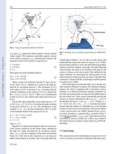
Fig. 2 Unicycle’s parameters and frame definition<br />
wleft and wright express the wheels angular velocity, and the<br />
control inputs. <strong>The</strong> maximum achievable angular velocity<br />
of the wheels is denoted wmax. Following this notation, the<br />
kinematic model of the unicycle is expressed as:<br />
˙x = u cos ψ,<br />
˙y = u sin ψ,<br />
˙ψ = r.<br />
<strong>The</strong> expression of the actuation model is:<br />
wleft = (u − Lr)/R,<br />
(2)<br />
wright = (u + Lr)/R.<br />
Define a path to be followed, denoted P, and a Serret-<br />
Frenet frame {F(s)}, attached on a point of the path defined<br />
by its curvilinear abscissa s. <strong>The</strong> orientation of {F }<br />
with respect to {O} is denoted as ψF . Assuming that the<br />
absolute coordinates of the origin of {F(s)} is denoted by<br />
PPF =[xF (s), yF (s)] T , TPF(s) =[PPF,ψF ] is defining the<br />
posture of {F(s)}, also called in the sequel path-followingtarget.<br />
Clearly, the robot position PR can be expressed as [x,y] T<br />
in {O} or [s1,y1] T in {F(s)}. Let define the path curvature<br />
of the point located at s, asc(s). <strong>The</strong> introduction of the<br />
variable θ = ψ − ψF , and the combination with (1), yields<br />
to the kinematic model of the unicycle in {F } as:<br />
˙s1 =−˙s(1 − cy1) + u cos θ,<br />
˙y1 =−c˙ss1 + u sin θ,<br />
ω = r − c˙s<br />
where ω = ˙θ.<br />
Equation (3) captures the kinematic behavior of the unicycle<br />
<strong>system</strong>, expressed in the Frenet frame, attached to<br />
the path on a point described by its curvilinear coordinate<br />
s. (s1,y1) are the coordinates of the robot in the Frenet<br />
frame {F }. Note that in this expression, we are using an<br />
added virtual degree of freedom, that is the path following<br />
(1)<br />
(3)<br />
Fig. 3 Proximity sensors and <strong>safe</strong>ty maneuvering zone (SMZ) definition<br />
virtual target evolution ˙s. As we will see in the sequel, and<br />
mathematically stated and solved in Lapierre et al. (2006),<br />
this procedure permits to solve the path following problem<br />
without restriction. Indeed, classically, for path following<br />
control design, the point to be reached on the path by the<br />
<strong>system</strong> is chosen as the closest point. This method has the<br />
major drawback of constraining the initial position of the<br />
robot in function of the maximum curvature of the path. This<br />
constraint is relaxed with the virtual target method reported<br />
in Lapierre et al. (2006).<br />
In the following we use the subscript (.)OA to design variables<br />
related to Obstacle Avoidance. For <strong>obstacle</strong> <strong>avoidance</strong><br />
purpose, the robot is equipped with m proximity sensors,<br />
pointing in m different directions regularly distributed on<br />
the robot, and concurrently crossing onto the middle point of<br />
the rear wheels axis. <strong>The</strong>se sensors periodically provide the<br />
distance to <strong>obstacle</strong> information as d =[d1,d2,...,dm] T in<br />
the absolute direction α =[α1,α2,...,αm] T . Clearly, αi =<br />
ψ + (2π)(i/m), fori = 0,...,m− 1. Consider the sensor<br />
that provides the smallest di, and define COA as the absolute<br />
position of that closest sensor/<strong>obstacle</strong> intersection. Define<br />
a <strong>safe</strong>ty maneuvering zone (SMZ), denoted SOA(rS, COA),<br />
as a circle of radius rS centered in COA, as shown in Fig. 3.<br />
Consider the point POA =[xOA,yOA] T as the intersection between<br />
PRCOA and SOA. Define TOA =[POA,ψOA], called in<br />
the sequel <strong>obstacle</strong>-<strong>avoidance</strong>-target, where ψOA will be defined<br />
later.<br />
3 Control design<br />
This section presents the methodology to design a low-level<br />
reactive Guidance and Control sub<strong>system</strong>, that aims at pre