Maraton Remote Controller Data Sheet - CERN - PH-ESE group
Maraton Remote Controller Data Sheet - CERN - PH-ESE group
Maraton Remote Controller Data Sheet - CERN - PH-ESE group

You also want an ePaper? Increase the reach of your titles
YUMPU automatically turns print PDFs into web optimized ePapers that Google loves.
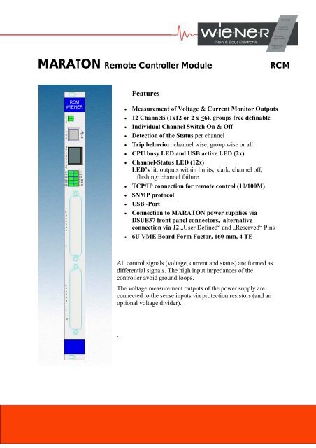
MARATON <strong>Remote</strong> <strong>Controller</strong> Module RCM<br />
RCM<br />
WIENER<br />
Features<br />
• Measurement of Voltage & Current Monitor Outputs<br />
• 12 Channels (1x12 or 2 x
Technical data<br />
Power requirement: 5V +/- 5 %, max. 1,5 A<br />
Operation temperature: 0....50°C without derating, storage: -30°C till 85°C<br />
Controllable Items of the MARATON DC/DC Converter:<br />
Current trip: programmable remotely. Trip of individual channel or channel <strong>group</strong>s<br />
Voltage trip: discharge of output capacitors after tripping and DC off.<br />
Over voltage trip: Fix point adjustment in MARATON (not changeable remotely)<br />
Temperature trip: Fix point setting in MARATON (not changeable remotely)<br />
Control outputs: Reaction delay < 5ms<br />
Monitor inputs: analog Voltage channel wise<br />
Input Common Mode Range +/- 60 V<br />
Differential input voltage range min. 50 V<br />
Input resistance min. 400 kOhm<br />
Measurement rate min. 500/s<br />
analog Current channel wise<br />
Differential input voltage range min. 5 V<br />
Input resistance min. 100 kOhm<br />
Measurement rate min. 500/s<br />
digital: Status information channel wise<br />
Tripping: within 5ms if programmed or fixed limits (overload, overheat, over<br />
voltage) exceed. Channel wise, <strong>group</strong> wise or global programmable.<br />
M T B F: at 40°C ambient /cooling air >120 000 h<br />
Input /output connection 1. Via front panel access through 37 pin Sub D (each per 6<br />
channels)<br />
2. By use of J2 connector<br />
Communication: Ethernet 10/100M, USB 2<br />
2
1. Connection to MARATON <strong>Remote</strong> <strong>Controller</strong><br />
DSUB37 male 1 Pin Signal Comment 96pol<br />
19 NC reserved<br />
37 IMON+5 Current monitoring signal C16<br />
18 IMON-5 Current monitoring signal return A16<br />
36 UMON+5 Connected to the positive sense lines C15<br />
17 UMON-5 Connected to the negative sense lines A15<br />
35 XON5 Combined ON/Status line C12<br />
16 XON-RET5 ON/Status line return A9<br />
34 IMON+4 Current monitoring signal C14<br />
15 IMON-4 Current monitoring signal return A14<br />
33 UMON+4 Connected to the positive sense lines C13<br />
14 UMON-4 Connected to the negative sense lines A13<br />
32 XON4 Combined ON/Status line A12<br />
13 XON-RET4 ON/Status line return A9<br />
31 IMON+3 Current monitoring signal C11<br />
12 IMON-3 Current monitoring signal return A11<br />
30 UMON+3 Connected to the positive sense lines C10<br />
11 UMON-3 Connected to the negative sense lines A10<br />
29 XON3 Combined ON/Status line C9<br />
10 XON-RET3 ON/Status line return A9<br />
28 IMON+2 Current monitoring signal C8<br />
9 IMON-2 Current monitoring signal return A8<br />
27 UMON+2 Connected to the positive sense lines C7<br />
8 UMON-2 Connected to the negative sense lines A7<br />
26 XON2 Combined ON/Status line C4<br />
7 XON-RET2 ON/Status line return A1<br />
25 IMON+1 Current monitoring signal C6<br />
6 IMON-1 Current monitoring signal return A6<br />
24 UMON+1 Connected to the positive sense lines C5<br />
5 UMON-1 Connected to the negative sense lines A5<br />
23 XON1 Combined ON/Status line A4<br />
4 XON-RET1 ON/Status line return A1<br />
22 IMON+0 Current monitoring signal C3<br />
3 IMON-0 Current monitoring signal return A3<br />
21 UMON+0 Connected to the positive sense lines C2<br />
2 UMON-0 Connected to the negative sense lines A2<br />
20 XON0 Combined ON/Status line C1<br />
1 XON-RET0 ON/Status line return A1<br />
DSUB37 male 2 Pin Signal Comment 96pol<br />
19 NC reserved<br />
37 IMON+11 Current monitoring signal C32<br />
18 IMON-11 Current monitoring signal return A32<br />
36 UMON+11 Connected to the positive sense lines C31<br />
17 UMON-11 Connected to the negative sense lines A31<br />
35 XON11 Combined ON/Status line C28<br />
16 XON-RET5 ON/Status line return A25<br />
34 IMON+10 Current monitoring signal C30<br />
15 IMON-10 Current monitoring signal return A30<br />
33 UMON+10 Connected to the positive sense lines C29<br />
14 UMON-10 Connected to the negative sense lines A31<br />
32 XON10 Combined ON/Status line A28<br />
13 XON-RET4 ON/Status line return A25<br />
31 IMON+9 Current monitoring signal C27<br />
12 IMON-9 Current monitoring signal return A27<br />
30 UMON+9 Connected to the positive sense lines C26<br />
11 UMON-9 Connected to the negative sense lines A26<br />
29 XON9 Combined ON/Status line C25<br />
10 XON-RET3 ON/Status line return A25<br />
28 IMON+8 Current monitoring signal C24<br />
9 IMON-8 Current monitoring signal return A24<br />
27 UMON+8 Connected to the positive sense lines C23<br />
8 UMON-8 Connected to the negative sense lines A23<br />
26 XON8 Combined ON/Status line C20<br />
7 XON-RET2 ON/Status line return A17<br />
25 IMON+7 Current monitoring signal C22<br />
6 IMON-7 Current monitoring signal return A22<br />
24 UMON+7 Connected to the positive sense lines C21<br />
5 UMON-7 Connected to the negative sense lines A21<br />
23 XON7 Combined ON/Status line A20<br />
4 XON-RET1 ON/Status line return A17<br />
22 IMON+6 Current monitoring signal C19<br />
3 IMON-6 Current monitoring signal return A19<br />
21 UMON+6 Connected to the positive sense lines C18<br />
2 UMON-6 Connected to the negative sense lines A18<br />
20 XON6 Combined ON/Status line C17<br />
1 XON-RET0 ON/Status line return A17<br />
3
Control Crate: NIX-I Type, 7U with 1U fan space<br />
low turn fans for medium cooling efficiency<br />
Power supply: 5V 33A, 12V 6A<br />
Control Bus 6U backplane with J2 connectors, 17mm pins and rear shrouds<br />
usable for input / output signals<br />
Ordering Information<br />
Description Channels part No<br />
Control and Monitoring Module RCM, 6U VME (1 slot),<br />
12 analog control input, 1 ETHERNET interface 12 0R00.0000<br />
TCP/IP Software for RCM with OPC Server 0S00.0001<br />
Control Crate, NIXI-C, VME 6U +1U fan unit 21 x 12 0300.M921<br />
4