RAO2321029 FIRE FIGHTING SKID
RAO2321029 FIRE FIGHTING SKID
RAO2321029 FIRE FIGHTING SKID

Create successful ePaper yourself
Turn your PDF publications into a flip-book with our unique Google optimized e-Paper software.
<strong>RAO2321029</strong><br />
<strong>FIRE</strong> <strong>FIGHTING</strong> <strong>SKID</strong>
MANUFACTURER IDENTIFICATION:<br />
NAME:<br />
ADDRESS:<br />
ID NUMBER:<br />
CHARACTERISTICS OF THE EQUIPMENT:<br />
NAME:<br />
DESCRIPTION:<br />
and FUNCTION<br />
MFR. NUMBER: MFR.YEAR:<br />
GROUP:<br />
EQUIP. CLASS:<br />
Acc. to 718/2002<br />
LOCATION:<br />
BASIC TECHNICAL PARAMETERS:<br />
MAWP: BarA POWER: MW<br />
COOLER CAPACITY: m3 LENGTH (PIPELINE ONLY): m<br />
GAS TYPE:<br />
COUNTRY:<br />
REGULATION AND STANDARDS:<br />
SANCO S.p.A.<br />
Via Ravizza, 13/A<br />
28066 GALLIATE, (Novara)<br />
ITALY<br />
<strong>FIRE</strong> <strong>FIGHTING</strong> <strong>SKID</strong><br />
CO2 High Pressure Fire Fighting System for two Gas Turbine placed inside enclosure<br />
<strong>RAO2321029</strong> 2009<br />
GAS APPLIANCE<br />
B.b<br />
Gas Station of Velke Kapusany (SLOVENSKY)<br />
90 N/A<br />
NA N/A<br />
FUEL GAS: CO 2<br />
NFPA12 / NFPA850
Testa S. Cecchini R.<br />
Electronically approved draw. GE NuovoPignone Internal DT-'N'
SANCO<br />
Fire Protection and Safety Technology<br />
NUOVO PIGNONE S.p.A.<br />
<strong>FIRE</strong>NZE<br />
ORDER NUMBER: 439526393-396<br />
JOB NUMBER: 1608941-42<br />
<strong>FIRE</strong> <strong>FIGHTING</strong> SYSTEM INSTRUCTION MANUAL<br />
FOR GAS TURBINE MODEL PGT25 PLUS<br />
SPP SLOVAKIA<br />
VELKE KAPUSANY (SLOVAKIA)<br />
COMPRESSION RATIO INCREASE<br />
AT COMPRESSOR STATION CS 01<br />
SANCO S.p.A. - Sede Legale, Uffici e Stabilimento: Via Ravizza, 13/A - 28066 GALLIATE (Novara) Italy<br />
Telefono +39 0321 80 75 75 - Fax +39 0321 80 66 99 - Capitale Sociale: Euro 1.500.000 i.v.<br />
Partita I.V.A. 01842700039 - Codice Fiscale e n° Iscrizione Registro Imprese di Novara: 01842700039<br />
N° R.E.A. 199945<br />
e-mail: sanco@sanco-spa.it - www.sanco-spa.com<br />
File: 08MG3847CE_R0.doc<br />
Page 1 of 29
INDEX<br />
SANCO<br />
Fire Protection and Safety Technology<br />
1. PURPOSE Page 4<br />
2. HEALTH AND SAFETY Page 5<br />
2.1. SAFETY REQUIREM Page 5<br />
2.2. GAS TOXICITY Page 5<br />
2.3. CO2 CYLINDER DANGER Page 5<br />
2.4. ELECTRIC SAFETY Page 5<br />
3. GENERAL NOTES REGARDING CARBON DIOXIDE Page 6<br />
3.1. CO2 SYSTEMS FIELD APPLICATION Page 6<br />
3.2. CARBON DIOXIDE NOMENCLATURE Page 7<br />
4. CO2 SYSTEMS GENERAL DESCRIPTION Page 8<br />
4.1. CO2 CYLINDERS UNIT Page 8<br />
4.2. DISTRIBUTION NETWORK Page 8<br />
4.3. <strong>FIRE</strong> DETECTION AND <strong>FIRE</strong> ALARM SYSTEM Page 8<br />
4.4. SYSTEM OPERATION Page 9<br />
5. SCOPE OF THE SUPPLY Page 10<br />
5.1. SUPPLY CONSISTENCE Page 10<br />
5.2. ALARM SYSTEM Page 10<br />
5.3. DISTRIBUTION NETWORK Page 10<br />
5.4. SYSTEM SIZING Page 11<br />
5.5. CO2 CYLINDERS CABINET Page 12<br />
6. STORAGE REQUIREMENTS Page 13<br />
7. INSTALLATION PROCEDURE Page 14<br />
7.1. DOCUMENTATIONS Page 14<br />
7.2. TOOLS Page 14<br />
7.3. SAFETY RULES Page 14<br />
7.4. ASSEMBLY SEQUENCE Page 15<br />
CYLINDERS Page 15<br />
ELECTRIC ACTUATOR Page 16<br />
WEIGHING DEVICES Page 17<br />
CYLINDERS CABINET LAST OPERATIONS Page 17<br />
DISTRIBUTION NETWORK Page 18<br />
7.5. ASSEMBLY TOLLERANCES AND CONTROLS Page 18<br />
7.6. FINAL OPERATIONS Page 18<br />
7.7 FINAL CECK Page 19<br />
8. TEST PROCEDURE Page 20<br />
8.1. FUNCTIONAL TEST Page 20<br />
8.2. OPERATIONAL TEST Page 20<br />
9. SYSTEM OPERATIONS Page 22<br />
9.1. START-UP PROCEDURES Page 22<br />
9.2. NORMAL OPERATIONS Page 23<br />
9.3. SHUT DOWN PROCEDURE Page 23<br />
9.4. TROUBLESHOOTING Page 24<br />
File: 08MG3847CE_R0.doc<br />
Page 2 of 29
SANCO<br />
Fire Protection and Safety Technology<br />
10. INSPECTION AND MAINTENANCE Page 25<br />
10.1. INSPECTION ANT TEST Page 25<br />
10.2. MAINTENANCE Page 26<br />
11. INSTRUCTION FOR THE CYLINDERS RECHARGING Page 27<br />
11.1. REMOVAL Page 27<br />
11.2. RECHARGING Page 27<br />
11.3. REINSTALLATION Page 27<br />
12. SYSTEM DISMISSAL PROCEDURE Page 28<br />
13. ATTACHED DOCUMENTS LIST Page 28<br />
13.1. RECOMMENDED SPARE PARTS Page 28<br />
All the information in this manual must be read and understood before system installation or<br />
maintenance.<br />
Pay particular attention to the manual sections with note WARNING:<br />
the non observance of that notes can cause damage to the persons and/or equipments.<br />
File: 08MG3847CE_R0.doc<br />
Page 3 of 29
1. PURPOSE<br />
SANCO<br />
Fire Protection and Safety Technology<br />
The purpose of this manual is to provide the installer with the necessary information required for<br />
correct assembly of the systems and special apparatus, and furthermore, information regarding the<br />
inspections to be carried out and tests to be executed on the systems before being made available for<br />
use.<br />
This manual has also the scope to give the contractor or user the information necessary for the<br />
installation, preliminary and final verification, before the start-up of the system or of the special<br />
equipment supplied, and furthermore, information regarding the system maintenance.<br />
As this manual is not specific for type of system or equipment supplied, we have<br />
considered the common parts, recognizable in similar situations, with reference to other documents in<br />
which the characteristics of the components used are clearly described, as well as all the other<br />
information necessary for the installation and verification.<br />
File: 08MG3847CE_R0.doc<br />
Page 4 of 29
2. HEALTH AND SAFETY<br />
2.1. SAFETY REQUIREMENTS<br />
SANCO<br />
Fire Protection and Safety Technology<br />
Safety rules to be observed during the assembling and maintenance are those indicated by<br />
regulations in force, all further regulations prescribed by the purchaser or by the Authorities having<br />
jurisdiction and also, where applicable, European safety directive (Machinery directive 37/98,<br />
PED97/23, ATEX 94/9, EMC 89/336, low voltage 73/23).<br />
2.2. GAS TOXICITY<br />
The supplied fire - fighting system uses the carbon dioxide as an extinguishing agent. This normally<br />
appears in the form of odourless and colourless gas which, through rapid and severe expansion, will<br />
produce both a fall in temperature (because it is capable of evaporating quickly without leaving<br />
residue) and a reduction in the percentage of oxygen below the values which allow combustion.<br />
Carbon dioxide insulates more than air and does not corrode or damage any material.<br />
Carbon dioxide, which remains within a location, can be easily removed by airing or by mechanical<br />
ventilation because it is heavier than simple air.<br />
Due to the fact that a man can not breathe without difficulty in a room where carbon dioxide is present<br />
in any concentration higher than 3.5%, it is important to be extremely careful on entering a room in<br />
which even a small amount of gas has been released. Therefore, the use of breathing apparatus is<br />
very important.<br />
If a person should show symptoms of carbon dioxide suffocation, it is necessary to take that person<br />
out of the location immediately, then artificial respiration should be administered, like it would be in the<br />
case of drowning, oxygen has to be given in order to achieve revival. Carbon dioxide which remains<br />
within a location can be easily removed by airing or by mechanical ventilation because it is heavier<br />
than air.<br />
These operations should be carried out in the presence of a doctor.<br />
2.3. CO2 CYLINDERS DANGER<br />
Pressurized (charged) cylinders are extremely hazardous and, if not handled properly, are capable of<br />
violent discharge. This may result in serious bodily injury or property damage ; always handle carbon<br />
dioxide cylinders with care. Cylinders are factory equipped with a protection cap. This device is a<br />
safety feature and provide protection during handling.<br />
Do not move or handle a carbon dioxide cylinder unless the protection cap and the valve safety pin<br />
are installed. For cylinder installation and removing see the relative paragraphs.<br />
2.4. ELECTRIC SAFETY<br />
The supplied fire - fighting system has a power supply for electrical equipments.<br />
During any operation of assembly and maintenance for any electrical equipments, the system isolation<br />
from power supply is mandatory.<br />
File: 08MG3847CE_R0.doc<br />
Page 5 of 29
SANCO<br />
Fire Protection and Safety Technology<br />
3. GENERAL NOTES REGARDING CARBON DIOXIDE<br />
3.1. CO2 SYSTEMS FIELD APPLICATION<br />
Carbon dioxide can be used to extinguish fires caused by:<br />
- inflammable liquids (class B fires) and materials reacting in a similar way to fire exposures, i.e. give<br />
surface fires<br />
- inflammable gases (C class fires); in that case you need to check that after the extinction there is no<br />
formation of explosive atmosphere because of unburnt gas leaks<br />
- devices and electrical systems under tension<br />
- wood, paper, cloth, etc. (A class fires); normally in these cases a great quantity of CO2 and a long<br />
permanence of the same in atmosphere are necessary to allow for the slow decreasing of ambient<br />
temperature and of embers<br />
With CO2 there is no extinction of fires caused by:<br />
- products containing the oxygen necessary for combustion<br />
- metals and chemical products reacting to CO2, such as alkaline metals and titanium<br />
Extinguishing action of carbon dioxide is based upon the reduction of the concentration of oxygen in<br />
the air down to a level preventing combustion, at the same time the cooling caused by carbon dioxide<br />
discharge contributes, as a secondary effect, to extinction.<br />
After discharging it may be necessary to keep carbon dioxide in the environment even once the fire<br />
has been extinguished, in order to allow for the various objects to cool down and avoid new fires<br />
starting.<br />
The carbon dioxide at environmental conditions is at gaseous state, consequently it is used into closed<br />
rooms where the gas loss is moderate. It can be, however, used for the protection of open areas, by<br />
adopting proper techniques.<br />
File: 08MG3847CE_R0.doc<br />
Page 6 of 29
3.2. CARBON DIOXIDE NOMENCLATURE<br />
SANCO<br />
Fire Protection and Safety Technology<br />
The carbon dioxide is colourless, odourless, and electrically no-conductive, the density of which is<br />
higher than 50% the one of the air.<br />
TEMPERATURE ( °C )<br />
- Chemical formula: CO2<br />
- Molecular weight: 44<br />
- Volume mass<br />
at 0°C and at 0,101 MPa (abs.): 1,98 kg/m 3<br />
- Density relevant to the air: about 1,5<br />
- Steam tension at 21°C : 58,6 bar abs.<br />
- Triple point:<br />
- Critical point:<br />
CO2 Cylinders Pressure vs. Temperature Relation Diagram<br />
PRESSURE ( bar )<br />
Temperature: -55,6 °C<br />
Pressure: 5,17 bar abs.<br />
Temperature: 31°C<br />
Pressure: 73,75 bar abs.<br />
CYLINDERS<br />
FILLING RATIO<br />
NOTE 1 Temperature limits<br />
relevant to the system cylinders<br />
rack storage ambient<br />
(see NFPA12)<br />
NOTE 2 Valve safety device<br />
intervention point (250bar)<br />
NOTE 3 Critical point<br />
File: 08MG3847CE_R0.doc<br />
Page 7 of 29
SANCO<br />
Fire Protection and Safety Technology<br />
4. CO2 SYSTEMS GENERAL DESCRIPTION<br />
The following systems described were installed for fire - fighting protection of areas which have<br />
electrical apparatus and/or live wires, by means of high pressure type carbon dioxide systems.<br />
The system, of the fixed type, is made up of piping normally empty, connected to a set of CO2 storage<br />
cylinders.<br />
Nozzles of the open type, distributed and orientated in accordance with the applicable standards<br />
installed onto the piping, release the gas within the protected area to contain and extinguish the fire.<br />
The intervention of the system is activated automatically by means of the fire detection system which<br />
will power up the electric controls located on the pilot cylinder, and/or manually, on site, by means of<br />
suitable handle controls acting exclusively on the pilot cylinder of the CO2 storage set.<br />
The intervention of the pilot cylinder will control the opening of all other slave cylinders.<br />
The release of gas will activate, by means of a pressure device, the alarm signals, which will then be<br />
displayed as the intervention on the control panel.<br />
4.1. CO2 CYLINDERS UNIT<br />
The fire is extinguished thanks to the release within the protected areas of a calculated quantity of<br />
carbon dioxide stored on cylinders placed in a safe position, on a suitable rack.<br />
The quantity of carbon dioxide is calculated in accordance with Regulation number 12 of The<br />
American National Fire Protection Association (NFPA) and based upon the specific requirement of the<br />
project<br />
The cylinders are made of special carbon steel and tested up to 250 Kg. / cm 2 .<br />
Every cylinder is equipped with a special quick release valve and siphon, and complete with a safety<br />
disk against over-pressure.<br />
The bursting pressure of the safety disk is equal to 250 bar.<br />
Each cylinder is further provided with a mechanical weighing device, which indicates that the contents<br />
of the cylinders are max. 10% below their nominal charge.<br />
All the cylinders are connected to a manifold by means of flexible hoses. On the connections of the<br />
manifold, suitable check valves are installed.<br />
These allow the performance of the system even in the case of one or more disconnected cylinders<br />
for maintenance purposes.<br />
For cylinder unit controlled with pneumatic devices, the pilot cylinder check valves are supplied with a<br />
lateral coupling, for the connection of the pressurisation circuit of the pneumatic operator which<br />
controls the intervention of the system of levers of all the slave cylinders.<br />
4.2. DISTRIBUTION NETWORK<br />
The distribution network is made of piping of calculated thickness to cope with the pressure of the<br />
gas, connected by means of fittings junctions.<br />
Discharge nozzles, supplied with purposely calculated drills, are installed onto the piping in the ideal<br />
position.<br />
The quantity and the location of these nozzles are established according to the type of protection, the<br />
discharge time and the characteristics of the area and/or the protected equipment.<br />
4.3. <strong>FIRE</strong> DETECTION AND <strong>FIRE</strong> ALARM SYSTEM<br />
In the protected areas, for quick signalling and a subsequent immediate intervention, fire detection<br />
systems with smoke, gas or heat detectors are installed.<br />
The systems are controlled by main control panel located in the <strong>FIRE</strong> <strong>FIGHTING</strong> ROOM.<br />
In the field, near particular zone specified in the project, are placed several fire alarm devices as<br />
horns and flashing lamps to warning the personnel to evacuate immediately the area; moreover others<br />
devices as push buttons, are placed for a manual alarm call, manual discharge or shutdown function.<br />
Often, in proximity of the protected areas accesses, CO2 system status panels are installed to warning<br />
the personnel related to the CO2 system operations (ex. System “Auto” , “Inhibited” , “CO2 Discharge”).<br />
For the description of these systems see the relevant manual.<br />
File: 08MG3847CE_R0.doc<br />
Page 8 of 29
4.4. SYSTEM OPERATION<br />
SANCO<br />
Fire Protection and Safety Technology<br />
The automatic intervention of the system is activated by a detection system which will actuate by<br />
means of the electrical control the pilot cylinders and consequently the beginning of the gas discharge<br />
(the start discharge is normally delayed of 30 seconds).<br />
Part of the gas, by means of the pneumatic circuit of the check valve, will pressurise the pneumatic<br />
pistons; these ones, by means of their levers pull the opening control bars of all the interested<br />
cylinders.<br />
The actuation manual control by means of a push button will follow the above described logic of<br />
intervention.<br />
To signal the intervention of the system, on the discharge pipe is installed a pressure device (normally<br />
a pressure switch with manual reset), connected to the system alarm panel.<br />
For the emergency manual mechanical control, it is necessary to proceed as follows:<br />
- act on the pull handle on the cylinder rack, causing the immediately intervention and the gas<br />
discharge.<br />
WARNING: Before actuate the intervention devices, be sure that nobody is in the protected<br />
zone or it the nearby or communicant zones .<br />
The gas discharge is extremely dangerous for the people which should inhale it or for the<br />
rescuers if not provided with breathing apparatus.<br />
CARBON DIOXIDE GAS CAN CAUSE INJURY OR DEATH.<br />
File: 08MG3847CE_R0.doc<br />
Page 9 of 29
5. SCOPE OF THE SUPPLY<br />
SANCO<br />
Fire Protection and Safety Technology<br />
Scope of the supply is to protect from fire two gas turbines model PGT25 PLUS (GTG-A + GTG-B) for<br />
SPP Slovakia installed in Velke Kapusany Slovakia, plan Compression Ratio Increase At Compressor<br />
Station CS 01.<br />
5.1. SUPPLY CONSISTENCE<br />
The protection is composed by the following systems:<br />
- Alarm system<br />
- Extinguishing system<br />
The alarm system is composed by a series of signalling equipment to be installed on field.<br />
The extinguishing system is composed by a CO2 system mainly composed by a self-standing type<br />
cabinet in which there have been placed and pre-assembled all the cylinders and the relevant<br />
accessories for the good operation, and by a distributing network for the CO2 discharge.<br />
Fire detection system is not in the scope of the supply.<br />
5.2. ALARM SYSTEM<br />
The supply is completed by the following control and signalling equipment:<br />
• N.4 Low frequency sirens 24Vdc 112 db/m - EEx-d (in the field);<br />
• N.4 Red flashing lamps 24Vdc - EEx-d (in the field);<br />
• N.4 Push-Buttons EEx-d with glass to be broken (in the field);<br />
• N.2 Pressure Switches EEx-d for CO2 discharge signal.<br />
(installed inside cylinders cabinet: one for GTG-A – one for GTG-B).<br />
5.3. DISTRIBUTION NETWORK<br />
The distribution network of the CO2 system is realised by means of the following materials:<br />
• Galvanized steel piping welding free and galvanized steel fittings ASA3000 NPT outside turbine.<br />
• Distributing nozzles are composed by AISI nozzles having a threaded connection 1/2” NPT-F and<br />
an aluminium cone. The nozzle will be complete of holes, the number and the diameter of which is<br />
based on the CO2 quantity that must be discharged at the pressure that there is at the nozzle.<br />
File: 08MG3847CE_R0.doc<br />
Page 10 of 29
5.4. SYSTEM SIZING<br />
QUICK DISCHARGE<br />
- Protected volume: 60 m 3<br />
- Extinguishing type: CO2<br />
SANCO<br />
Fire Protection and Safety Technology<br />
- Project concentration: 37% within the first min.<br />
- Quick discharge: 90 kg.<br />
- Total cylinders for quick discharge: N. 2 of 67 lt. / 45 kg.<br />
SLOW DISCHARGE<br />
- Protected volume: 60 m 3<br />
- Extinguishing type: CO2<br />
- Project concentration: 30% for 30 min.<br />
- Slow discharge: 135 kg.<br />
- Total cylinders for slow discharge: N. 3 of 67 lt. / 45 kg.<br />
NOTE:<br />
Reserve battery – one set of CO2 Cylinders (N°5) as spare in loose are supplied<br />
File: 08MG3847CE_R0.doc<br />
Page 11 of 29
5.5. CO2 CYLINDERS CABINET<br />
SANCO<br />
Fire Protection and Safety Technology<br />
The cylinders, necessary for the extinction of an eventual fire which can develop in the turbine cabinet,<br />
are placed on a self-standing cabinet.<br />
This cabinet has the following dimensions in mm: 2010x930xh.2380.<br />
Inside the cabinet there are assembled N.10 cylinders 67lt. cap. charged with 45 kg. of CO2 necessary<br />
for the turbine protection: N.5 cylinders for gas turbine GTG-A, and N.5 cylinders for gas turbine GTG-<br />
B; for each bank n.2 cylinders are for the Quick discharge and n.3 cylinders are for the Slow<br />
discharge. Two cylinders of each group, GTG-A and GTG-B, will be equipped with opening electric<br />
control 24Vdc. Two pressure switches are installed on the CO2 manifold (quick discharge) to signalling<br />
the system intervention (one for GTG-A and one for GTG-B).<br />
On each discharge piping (Quick and Slow) is mounted a lockable cut-off valve c/w limit switches and<br />
a safety valve set 140bar.<br />
The rack is moreover equipped with two (2) junction boxes:<br />
- One for the digital signals (JB29)<br />
- One for solenoid valves (JB28)<br />
All the cylinders are equipped with counterbalance weighing device for the discharged cylinder<br />
signalling.<br />
Such a system allows to identify locally the discharged cylinder and to remote transmit, by means of<br />
limit switch, the alarm signalling.<br />
On each lateral wall there is installed a handle for the cylinders unit mechanical actuation discharge<br />
control (one for GTG-A and one for GTG-B).<br />
File: 08MG3847CE_R0.doc<br />
Page 12 of 29
6. STORAGE REQUIREMENTS<br />
SANCO<br />
Fire Protection and Safety Technology<br />
All materials necessary to carry out the installation are dispatched in suitable packages in accordance<br />
with the Purchaser specifications.<br />
Ordinary mechanical materials, loose components concerning pipes, supports and prefabricated pipes<br />
are usually contained in crates or wooden cases.<br />
Special mechanical materials and ordinary electric ones, or particular equipment are usually contained<br />
in wooden cases, and inside its original package: cardboard boxes or little light wooden cases.<br />
Special electric material is normally contained in wooden cases, inside are barrier sacks together with<br />
salts against dampness, in its original packages: cardboard boxes or little light wooden cases.<br />
During the whole transport and storage phase, the integrity of the material will have to be preserved by<br />
examining the packages. The packages should not be damaged so as to avoid damages of the goods<br />
themselves.<br />
A regular maintenance must be carried out, particularly as for packages containing electric materials<br />
which need for example a replacement of salts, and so on, according to specific instructions.<br />
All materials, except for pipes and steel drawn products, will have to be stocked in airy storehouses<br />
contained in their own original packages, till installation is carried out.<br />
Electric panels and electric / electronic components will have to be stocked in storehouses at an<br />
internal temperature not above a maximum of +45°C and not below a minimum of 0°C.<br />
Cylinders for gas storage, complete with protection caps, must be stored in covered and airy rooms,<br />
with an ambient temperature not higher than +54°C nor be less than –18°C.<br />
Heating or cooling shall be permitted to be used to keep the temperature range described above.<br />
File: 08MG3847CE_R0.doc<br />
Page 13 of 29
7. INSTALLATION PROCEDURE<br />
7.1. DOCUMENTATIONS<br />
SANCO<br />
Fire Protection and Safety Technology<br />
Be sure to have all the technical documents last revision furnished with the supply necessary for the<br />
erection of the system and as minimum:<br />
• CO2 cylinders cabinet assembly drawing<br />
• CO2 piping layouts<br />
• CO2 cylinders cabinet electrical wiring diagram<br />
7.2. TOOLS<br />
Suitable for the installation of the system are all usual tools for electric or mechanical installations,<br />
such as:<br />
• All usual tools normally used by electricians<br />
• All usual tools normally used by plumbers<br />
• Tools for the welding of carbon steel materials<br />
• Tools for cut and preparation of the pipes up to 4” diameter<br />
• Tools for cut and threat of pipes up to 4”<br />
• Suitable lifting systems<br />
• Stairs and scaffolds.<br />
All these equipment must be in accordance with all regulations in force and be in good condition.<br />
7.3. SAFETY RULES<br />
Safety rules to be observed during the assembling are those indicated by regulations in force, all<br />
further regulations prescribed by the purchaser or by the Authorities having jurisdiction and also,<br />
where applicable, European safety directive.<br />
Staff: Safety belts<br />
Safety helmets<br />
Glasses for welding and grinding<br />
Safe gloves<br />
Suitable clothes<br />
Suitable and safe shoes<br />
Work tools: According to rules for mechanical and electromechanical tools.<br />
Generally: Circumscribe the working area with indications of “NO ENTRY” for unauthorized<br />
persons.<br />
File: 08MG3847CE_R0.doc<br />
Page 14 of 29
7.4. ASSEMBLY SEQUENCE<br />
CYLINDERS<br />
SANCO<br />
Fire Protection and Safety Technology<br />
a) Pick out the position of the structure or container in the project drawings, and then locate and fix it<br />
to the ground by means of fixing bolts<br />
b) Connect hoses to the manifold, fitting in gaskets, locking well by a fixed key and not by clamps.<br />
c) Go on with the installation of cylinders hooking them to the weighing devices by means of suitable<br />
threaded collars and follow the indication:<br />
A) Before the installation make sure that the safety pin (1) is in the correct position<br />
(see CO2 valve details at the end of this manual)<br />
B) Screw down on the cylinder, the collar (2) c/w bars to be positioned on the balance<br />
C) Lift the cylinder (5).<br />
D) Engage the rods (6) in the suspense balance (7).<br />
E) Connect the cylinder valve (3) on the discharge hose (4) inserting the relevant gasket<br />
F) Place the electrical actuators on the valves of the pilot cylinders.<br />
PAY ATTENTION:<br />
The lever (8) of the valve (3) must be fixed on the same valve just when all the equipment has been<br />
assembled.<br />
For cylinder removing following backward this indication; but the first operation will be to insert safety<br />
pin.<br />
C<br />
D D<br />
WARNING: CO2 gas has a pressure equal to 58.6 bars at 21°C in the cylinders and consequently<br />
such cylinders must be handled with care; before moving them make sure that all the valve<br />
connections are duly closed, avoid knocks or accidental falls.<br />
Accidental gas discharge, from cylinders not fixed to the rack, is extremely dangerous. Do not move or<br />
handle a carbon dioxide cylinder unless the protection cap and the valve safety pin are installed.<br />
CARBON DIOXIDE GAS CAN CAUSE INJURY OR DEATH.<br />
C<br />
File: 08MG3847CE_R0.doc<br />
Page 15 of 29
ELECTRIC ACTUATOR<br />
SANCO<br />
Fire Protection and Safety Technology<br />
d) Install the electric controls on pilot cylinders<br />
LEGEND: 1 – Solenoid 5 – Stem with locking nuts<br />
2 – Bracket 6 – Valve lever<br />
3 – Cylinder valve 7 – Screws<br />
4 – Striker<br />
1) Mode of operation description<br />
Automatic operation: the release device open the valve (3) releasing the spring loaded striker<br />
(4) after the excitation of the solenoid which acts on the valve lever.<br />
Manual operation: the opening of the CO2 valve is controlled by acting directly on the lever (6).<br />
2) Device installation<br />
WARNING To avoid accidental openings operate after removing the lever (6), inserting the<br />
safety pin and connect the flexible hose.<br />
3) Test<br />
Fix the device on the support (2) by means of screws (7).<br />
Arm the device pushing the striker (4) in its housing than push completely the stem with locking<br />
nuts and the nuts (5) into the solenoid (1).<br />
Leave the striker that will remain locked to the device and the nut of the stem (5) in contact with<br />
the solenoid (5).<br />
Install the lever on the valve and ensure a distance of 2÷3mm between the lever and the striker,<br />
tightening the screw (7).<br />
Test the device after the installation.<br />
WARNING: The test must be carried on in security conditions, the cylinder fastened, the flexible<br />
hose connected to the manifold and safety pin inserted in the relevant hole. To test<br />
the device it is necessary to remove the lever (6) from the valve (3) to prevent the<br />
opening valve and accidental CO2 discharge.<br />
Energise the solenoid and verify that the spring loaded striker is been released.<br />
4) Resetting<br />
See above chapter 2.<br />
STAND-BY ACTUATED<br />
REMARKS: - don’t modify the nuts position on the stem (5)<br />
- remove the safety pin to permit the functioning of the system only when the<br />
system is placed into service.<br />
File: 08MG3847CE_R0.doc<br />
Page 16 of 29
WEIGHTING DEVICES<br />
SANCO<br />
Fire Protection and Safety Technology<br />
e) Set the weighing device positioning the counterweight as described<br />
The weighing device is used for indicating the weight of the extinguishing agent in the steel cylinders.<br />
The weight must be adjusted until a leakage indication is given when a max. of 10% weight-loss of the<br />
cylinder contents has occurred;<br />
Calibration according to the cylinder weight inclusive of its contents, different counter-weight are used<br />
Necessary counter weight for charged<br />
cylinders<br />
Weight Charged cylinder (kg.)<br />
kg. From To<br />
Adjusting constant (*)<br />
1,2 65 90 1,00 kg. / TURN<br />
1,6 95 125 1.50 kg. / TURN<br />
1,9 125 150 1,75 kg. / TURN<br />
2,3 150 185 2,00 kg. / TURN<br />
(*) The adjusting constant indicates the carbon dioxide weight variation signaled at every turn of the<br />
adjustable nut.<br />
Weighting device setting<br />
1. Screw the adjusting nut into the threaded stud until the weight stays in balance horizontal position.<br />
2. Turn the nut clockwise till a weight loss 10%.<br />
3. Lock the nut and lead the weight with copper wire.<br />
Example:<br />
CYLINDERS CABINET LAST OPERATIONS<br />
Cylinder weight Tot……..115 kg. 4 kg. = 2,5 Turns<br />
Cylinder content…………..40 kg. 1,5 kg. / TURN<br />
Adjusting constant………1,5 kg.<br />
Loss indication 10….…..…4 kg.<br />
f) Fit in valve cylinder levers extensions, with the exception of those relating to pilot cylinders.<br />
g) Connect the unit to “ground”.<br />
h) Connect the unit to the detection and control system electrically, and it will have to be and remain<br />
in a defused position.<br />
File: 08MG3847CE_R0.doc<br />
Page 17 of 29
DISTRIBUTION NETWORK<br />
Proceed in the following way:<br />
SANCO<br />
Fire Protection and Safety Technology<br />
i) Preparation of the non prefabricated pipes and supports including cleaning and execution of the<br />
protective coating according to specifications.<br />
j) Installation of necessary supports.<br />
k) Installation of pipes and tightening of the connections and supporting components.<br />
l) Installation of special equipment while taking into account the indications described in the<br />
Chapters 6.5 and 6.6 here below described for the execution of preliminary tests hampering the<br />
installation itself.<br />
m) Connection to the feeding unit.<br />
REMARK: all the threaded connections must be complete with dedicated sealing product as<br />
Loxeal 18-10 or equivalent, other materials as hemp or Teflon are not acceptable.<br />
7.5. ASSEMBLING TOLERANCES AND CONTROLS<br />
It is not necessary to carry out particular checks during the assembling works of the system or of the<br />
considered equipment.<br />
The dimensions indicated in the drawings will be considered with an average tolerance degree, as<br />
normally done in mechanical constructions executed for plumbers and carpenters works.<br />
Dimensions to be observed are mainly those ones concerning the positioning of supports and special<br />
components.<br />
Particular care will be taken for the erection of the nozzles and of the system instruments.<br />
REMARK: the piping system shall be installed in accordance with the approved system plans and the<br />
latest version of SANCO CO2 flow calculation program; any deviation from the system plans or flow<br />
calculation program must be approved by SANCO and a system flow calculation performed to confirm<br />
the acceptability of the changes.<br />
7.6. FINAL OPERATIONS<br />
At the end of each erection work, the following operations will be carried out according to the different<br />
system sections.<br />
a) Cylinders units:<br />
• The electric system of whole group will be submit to test operations together with ones relating to<br />
signaling and control system, described in the relevant manual.<br />
b) Distribution net:<br />
• Carry out a pneumatic test on the whole circuit, by pressurizing with compressed air or nitrogen, in<br />
order to verify the tightness of the couplings and the integrity of the components. The test pressure will<br />
be about 3 bar. The period of the test will be at least 10’. Longer periods will be expressly indicated on<br />
the project documents.<br />
• A test pressure decrease within 20% after 10’ will be acceptable.<br />
During the test possible leakage will be verified. They will have to be eliminated and the test will have<br />
to be repeated till the relevant result will be positive.<br />
The cut-off valves must be closed and instead of the nozzles, caps will be assembled.<br />
The verification can be carried out in different system section, in case the system is particularly<br />
extended or in case some particular considerations are necessary.<br />
File: 08MG3847CE_R0.doc<br />
Page 18 of 29
SANCO<br />
Fire Protection and Safety Technology<br />
• At the end of the pneumatic test, removing all the caps and carry out the blowing of the piping by<br />
means of inlet of compressed air or nitrogen.<br />
The flow must have the direction from control unit to nozzles.<br />
Clean any obstructed connection and all the dirty traps at the end of the pipe line, even if partially,<br />
before reinstalling the nozzles.<br />
At the end of the operation install the nozzles, taking care that all the couplings are tightened.<br />
REMARK: the CO2 system include a variety of discharge nozzles, each designed for a specific<br />
application or flow rate: all nozzles have discharge orifices drilled to suit the specific nozzle location<br />
and discharge flow requirements (see the stamped values on each nozzle).<br />
When installing nozzles, it is imperative that the correct nozzle be installed in its appropriate location<br />
within the system discharge piping network (refer to the CO2 piping layout drawing to find the exactly<br />
location of each nozzle): the not respect of such indications involve a not corrected discharge<br />
inside the specified protected area.<br />
c) Whole system:<br />
• Check that the installation is complete and that the nozzles and the special components have been<br />
correctly placed.<br />
Issue test reports indicating that the final operations have been carried out. The documents should be<br />
complete with the registered data, the date and the name of the persons who took part in the<br />
operations.<br />
7.7. FINAL CHECK<br />
a) Cylinders units :<br />
• Verify that the structures are well fixed both among them and to the floor, the counterweight of<br />
weighing devices are locked between the relevant nuts and lock nuts, the pneumatic circuits are<br />
connected and couplings well closed.<br />
• Verify that all electric equipment are correctly connected, but that the relevant control panels are<br />
not energized.<br />
For all operations of test of the control and signaling circuits, refer to the relevant manuals.<br />
b) Distribution system<br />
• Verify that the pipes are completely assembled and connected and supports are well fixed on the<br />
structures, walls and ceilings; the discharge nozzles are installed in its appropriate locations and<br />
supplied with protecting screen.<br />
c) Protected area :<br />
• Verify that all pipes passing through walls and ceilings are sealed; all openings, that are not<br />
considered in the system calculations, are sealed or supplied with automatic closing devices; the<br />
existence of all warning intervention devices to evacuate the protected area.<br />
d) Whole system<br />
• Carry out the test operations as below described, in order to verify, where possible, the correct<br />
working of the equipment before the possible “START UP”.<br />
File: 08MG3847CE_R0.doc<br />
Page 19 of 29
8. TEST PROCEDURE<br />
SANCO<br />
Fire Protection and Safety Technology<br />
At the end of the control operations previously described, proceed with the hereunder listed test<br />
operations.<br />
8.1. FUNCTIONAL TEST<br />
Carry out the functional test of the different components in order to make sure of their working, without<br />
causing the intervention of the extinguishing systems but only the activation of signaling and control<br />
devices, connected to the different components or controlled by them.<br />
• Test the pressure switch pushing in the internal piston<br />
(see relevant manual for others pressure devices as pressure transmitters).<br />
• Test the electromechanical controls with lever extension of pilot cylinder valves disconnected<br />
from the same valves, in order to verify their activation by means of an electric impulse controlled<br />
by the relevant control panel.<br />
• Check the intervention of the weighing switches, by putting up cylinders lightly, till they will operate.<br />
• Check the correct function of other devices if any (cut-off valve limit switches, selector switches,<br />
etc.)<br />
8.2. OPERATIONAL TEST<br />
As per NFPA12 requirements, each carbon dioxide system must be tested with full gas discharge in<br />
order to make sure that the project characteristics are observed, causing the intervention of the<br />
systems with the distribution of the extinguishing agent in the considered area.<br />
For this test we suggest to contact a Fire Fighting Company or equivalent agency, agreed with<br />
authority having jurisdiction.<br />
The execution of the test must be entrusted to trained personnel, who are also provided with all<br />
necessary safety equipment.<br />
All CO2 systems testing should successfully accomplish the following:<br />
• Check the integrity of the piping distribution including cylinders rack, supports and anchors.<br />
• Verify detector operation.<br />
• Verify audible and/or visual alarm operation.<br />
• Verify manual release operation.<br />
• Verify that all interlock and shutdown functions operate and occur at the appropriate time in the<br />
system discharge sequence.<br />
• Actuation sequence conforms to the intended design and pre-discharge time delays (if provided),<br />
operates correctly and with the correct time delay period.<br />
• All pressure operated devices function as intended at the correct point in the firing sequence.<br />
• All safety and warning features are in place and operate satisfactorily.<br />
• Design concentration is attained within the appropriate time in accordance with NFPA 12.<br />
• Designed concentration levels are attained and remain in the hazard area for the period of time<br />
specified. The ability to reach and maintain concentration levels is STRICTLY dependent upon the<br />
construction of the enclosure and measures taken to prevent agent loss. Total flood systems<br />
perform best when agent loss due leakage from the enclosure is held a minimum.<br />
File: 08MG3847CE_R0.doc<br />
Page 20 of 29
SANCO<br />
Fire Protection and Safety Technology<br />
REMARK: performing a “Room Integrity Fan Test” is strongly recommended prior to conducting a<br />
discharge test; this test is “non-destructive” and will help to find the points of possible hazard leakage<br />
that can be sealed and secured before the discharge test is performed.<br />
In order to carry out the “OPERATING TESTS”, it will be necessary to complete the assembly of<br />
extension pilot cylinder levers and the removal of all safety pins of cylinder valves.<br />
At the end of the test, a final test report has to be issued, signed by all persons representing the firm<br />
charged with the installation, the purchaser / final customer.<br />
On the report all data relevant to the test and possible remarks will have to be indicated.<br />
File: 08MG3847CE_R0.doc<br />
Page 21 of 29
9. SYSTEM OPERATIONS<br />
9.1. START-UP PROCEDURES<br />
SANCO<br />
Fire Protection and Safety Technology<br />
When the systems are completely tested, as indicate in the above chapters, the following control<br />
operations must be executed:<br />
a) Cylinder battery, please check:<br />
• that the structures are properly fixed, one to the other and to the floor;<br />
• that the counter weights of the weighing devices are blocked within the relevant nuts and bolts;<br />
• the pneumatic circuits are properly connected and the fittings properly sealed<br />
• the electric circuit are connected to the equipment and to the signalling and control system<br />
• the safety pins are positioned in the valves<br />
• set and rearm the controls without positioning the lever extensions<br />
• with the cylinder lever extensions disconnected from the same valve, test the electro- mechanical<br />
control with the actuation by means of electrical impulse controlled by the relevant panel<br />
• lift slowly the cylinder to verify the action of the weighing device and the click of the related limit<br />
switch<br />
• actuate by means of the relevant internal piston the “system intervened” pressure switch (for this<br />
operation the pressure switch will be disconnected from their coupling). For others pressure<br />
devices as pressure transmitters see the relevant manual.<br />
b) Distribution net, please check:<br />
• The piping are completely assembled, connected and the supports are properly fixed on the<br />
structures, walls and ceilings;<br />
• The CO2 nozzles are installed<br />
c) Protected area, please check:<br />
• All passages of the piping through walls and ceilings are well sealed;<br />
• All the openings, non considered in system calculation are sealed or provided with automatic<br />
closing devices at the system intervention;<br />
• All the pre-alert devices for the evacuation of the protected area are correctly installed and visible<br />
REMARKS: - start up of the CO2 system can be effected only if the detection system has<br />
been inspected and tested as described in the relevant manual.<br />
- to make the system working it is necessary to authorize the “AUTOMATIC” function<br />
in the control panel. At the end of all the above described operations, verify that the<br />
control panel is fully functioning and that it does not signal any fault or alarm condition.<br />
WARNING: After system installation and start-up procedure remove the safety pins<br />
from the cylinders and open cut-off valves.<br />
NOW THE SYSTEM IS READY TO BE “STARTED”<br />
File: 08MG3847CE_R0.doc<br />
Page 22 of 29
9.2. NORMAL OPERATIONS<br />
SANCO<br />
Fire Protection and Safety Technology<br />
Once the system here described is working in accordance with all procedures described in the<br />
previous chapters and is kept in perfect condition always in accordance with the maintenance<br />
instructions described in the proper chapters of this manual, is in a position of operate in an<br />
independent way on condition that all required values concerning pressure and flow are respected.<br />
At the same time, also detection and control system must be on operating condition, as indicated in<br />
the relevant manual.<br />
Particular care must be taken as for new structures or storage conditions of the goods in the protected<br />
hazard do not imply the good working of the same, or modify the characteristics of the protected<br />
hazard, making the system not suitable.<br />
9.3. SHUT DOWN PROCEDURE<br />
WARNING The system should be placed out of service only for repairs. The work to be done must be<br />
completed in a manner to minimise the time that the system must be out of service. All hazardous<br />
activities in the effected area shall be terminated until the system is placed back in service. Any<br />
system impairment shall be co-ordinated with the owner, local authority having jurisdiction and other<br />
related parties. Place a roving fire patrol in the area covered by the system until the system is back in<br />
service.<br />
Prior to turning off any valves or activating any alarms, notify local security guards and/or central alarm<br />
station (if used) so that a false alarm will not be signalled and result in a local fire department<br />
response.<br />
After the precautions indicated above and before any disassembly of the parts of the system, follow<br />
the instructions listed below:<br />
• Close cut-off valve;<br />
• Disconnect the pneumatic line which controls the pneumatic operators that open the cylinders from<br />
the discharge collector;<br />
• Disconnect the opening control levers of the valves mounted on the pilot cylinder;<br />
• Put, in the appropriate drills, the shear pins which are fixed to the valves body by a small wire rope<br />
inhibiting the function of the valve itself;<br />
• Put “SYSTEM OUT OF ORDER” warning notices into positions where they can be well noticed;<br />
REPAIRS: When necessary, owing to intervention or damages occurred, please execute repairs and<br />
mind to use same material as the original ones and following in this way the initial project.<br />
Any difference need to be approved in writing, by SANCO or by the local Authority having jurisdiction.<br />
Repairs must be carried out in accordance with the guidelines of the operations described in the<br />
previous chapters.<br />
RESTART: See Section 8.1 of this Manual “START-UP PROCEDURES” for all operations<br />
concerning the operative restoration of the system. At the end of those operations which have required<br />
the replacement of some parts, the components which are normally stored as spare parts and which<br />
have been used for repairs, should be replaced; the new components should be identical to those<br />
which have been used for repairs or of an equivalent type, authorised by the Manufacturer.<br />
File: 08MG3847CE_R0.doc<br />
Page 23 of 29
9.4 TROUBLESHOOTING<br />
SANCO<br />
Fire Protection and Safety Technology<br />
Due to the fact that the CO2 components do not function continuously, they manifest a low degree of<br />
wear. Therefore, with normal use and preventive maintenance carried out, protecting against corrosion<br />
and eventual mechanical damage caused by accidental impacts, the system should be reliable for a<br />
long time.<br />
PROBLEM TABLE<br />
Problem Possible Cause Corrective Action<br />
At the intervention the control electrical<br />
heads does not operates<br />
• Interrupted electrical<br />
connection<br />
• Device failure<br />
Intervention of the weighing device • Discharged CO2 cylinders<br />
(-10%)<br />
• Unbalanced device setting<br />
The cylinder valve does not open on pull<br />
handle intervention<br />
• The control cable is not<br />
properly installed<br />
• The extension of the control<br />
lever is not properly installed<br />
The discharge time is too long • The nozzle drills are partially<br />
blocked<br />
The weighing device does not indicate<br />
position of an empty cylinder<br />
• The weighting device is not<br />
set properly<br />
• Check the<br />
electrical<br />
connections<br />
between the<br />
panel and the<br />
device<br />
• Replace the<br />
device<br />
• Refill the<br />
cylinders and<br />
reset the<br />
weighing devices<br />
• Set the weighing<br />
device<br />
• Check the<br />
connection of the<br />
control table<br />
• Install the control<br />
lever extension<br />
• Remove the<br />
obstruction from<br />
the nozzles after<br />
disassembling<br />
them<br />
• Set the weighing<br />
device<br />
File: 08MG3847CE_R0.doc<br />
Page 24 of 29
10. INSPECTION AND MAINTENANCE<br />
10.1. INSPECTION AND TEST<br />
SANCO<br />
Fire Protection and Safety Technology<br />
It is imperative that the system must be inspected and tested on a regular basis. The following<br />
recommendations are minimum requirements, the frequency of the inspection may vary due, in<br />
function of the system operating condition, for example in case of particularly aggressive atmospheres.<br />
Prior to testing the equipment, notify appropriate personnel.<br />
All inspections and tests here below described, must be carries on by qualified personnel and results<br />
must be reported on a proper document with all eventual notes for repairs or removal of differences<br />
from original projects.<br />
INSPECTION TABLE<br />
The minimum inspection operations to carry out on the system, complete with a note which indicates<br />
the time scale with which these operations must be executed, are listed below.<br />
PROCEDURE DESCRIPTION<br />
Check the electrical connections to the control head, to<br />
the pressure devices and to the micro switches at the<br />
weighing devices.<br />
Check that the extensions of the CO2 valve control<br />
FREQUENCY<br />
W M S A<br />
X<br />
NOTES<br />
After every maintenance<br />
or intervention<br />
levers are installed.<br />
X<br />
After every maintenance<br />
or intervention<br />
Check that the system has not suffered any damage<br />
and, if this is the case, repair them.<br />
X<br />
After every maintenance<br />
or intervention<br />
According to local<br />
Check the expiry date of the CO2 cylinder test. X regulation (ie: in Italy<br />
every 5 years)<br />
Check the “armed” or “rest” position of the electric<br />
controls and pressure switches.<br />
X<br />
After every maintenance<br />
or intervention<br />
Verify that the safety pins are removed from the cylinder<br />
valves.<br />
X<br />
After every maintenance<br />
or intervention<br />
Check the pneumatic connection between the manifold<br />
and the pneumatic actuators.<br />
X<br />
After every maintenance<br />
or intervention<br />
Check the correct assembling of the control bars, of the<br />
CO2 valve opening and the good connection of the pull<br />
handles.<br />
X<br />
After every maintenance<br />
or intervention<br />
Check that the nozzles are free for CO2 diffusion. X After every intervention<br />
W = Weekly M = Monthly S = Six-Monthly A = Annual<br />
File: 08MG3847CE_R0.doc<br />
Page 25 of 29
SANCO<br />
Fire Protection and Safety Technology<br />
TEST TABLE<br />
The periodical tests which must be executed on the system and the expiry dates for the execution of<br />
these tests, are listed below.<br />
10.2. MAINTENANCE<br />
PROCEDURE DESCRIPTION<br />
1. Operate the control heads, after removing the levers<br />
extension, by means of the control panel<br />
2. Simulate the intervention of the pressure switches,<br />
by means of a bridge between its contacts or by<br />
pushing the internal piston.<br />
For others pressure devices as pressure transmitters<br />
see the relevant manual<br />
FREQUENCY<br />
W M S A<br />
NOTES<br />
CO2 systems and Detection Alarm system components, since they are not continuously in operation,<br />
have a low wear degree.<br />
Therefore a normal use and a preventive maintenance carried out as protection from corrosion and<br />
from possible mechanical damages which should be caused by accidental impacts allow the system to<br />
have lifelong reliability.<br />
Here below you will find the recommended maintenance operations and the relevant expiry dates on<br />
which the same must be effected.<br />
MAINTENANCE TABLE<br />
PROCEDURE DESCRIPTION<br />
FREQUENCY<br />
W M S A<br />
NOTES<br />
1. Execute maintenance of the CO2 cylinder valves<br />
which is indicated on CO2 valve details.<br />
X<br />
After every maintenance<br />
or intervention<br />
2. Flexible hoses: as soon as they show damage on<br />
When it is necessary<br />
their surfaces with aged or worn-out rubber coatings, - - - - during inspection or<br />
they have to be replaced immediately.<br />
after the intervention<br />
3. Painting touch-up: it is advised to touch-up all the<br />
points where the paint is damaged in order to avoid<br />
corrosion in every part of the system.<br />
- - - -<br />
When it is necessary<br />
during inspection<br />
After every intervention<br />
4. Remove the nozzles and clean the drills. - - - - or when it is necessary<br />
during inspection<br />
W = Weekly M = Monthly S = Six-Monthly A = Annual<br />
X<br />
After every maintenance<br />
or intervention<br />
WARNING The activation of these pressure devices<br />
will cause the intervention of the alarms<br />
3. Check the functionality of all the weighing device. X<br />
After every maintenance<br />
or intervention<br />
W = Weekly M = Monthly S = Six-Monthly A = Annual<br />
X<br />
After every maintenance<br />
or intervention<br />
File: 08MG3847CE_R0.doc<br />
Page 26 of 29
SANCO<br />
Fire Protection and Safety Technology<br />
11. INSTRUCTION FOR THE CYLINDERS RECHARGING<br />
When, after an intervention discharge or for the restoration of the nominal charge of the extinguishing<br />
agent, it is necessary to refill the cylinders, proceed as follows.<br />
WARNING CO2 cylinders should never be handled or moved without the protective safety cap<br />
securely in place. DO NOT remove this cap until the cylinders have been installed in to their rack.<br />
11.1. REMOVAL<br />
• Temporarily put the system out of order, acting on the control and signalling panel, according to the<br />
procedures described in the relevant manual<br />
• Verify that all precautions have been taken, in order to act in complete safety condition on the<br />
cylinders batteries, included the warning by means of a proper notice indicating ‘SYSTEM OUT OF<br />
ORDER’.<br />
• Disarm the emergency control systems, where existing and the electromechanical controls of the<br />
cylinders and on the release cabinet.<br />
• Draw off the valve lever from the cylinder valve.<br />
• Disconnect the discharge hose from the cylinder.<br />
• Disconnect the cylinder from the rack following backwards the indications contained in the chapter<br />
concerning the installation of the same.<br />
• Send the cylinder to the supplier for relevant recharging and checking, it will have to be sent<br />
complete with the relevant protections (cap, seal, etc.)<br />
11.2. RECHARGING<br />
• Carry out the weighing of the cylinder for the definition of the quantity necessary for the restoring of<br />
the discharge conditions.<br />
• Verify if it is a restoration, the seal of the valve by means of proper liquids or sprays for searching<br />
of little leakage. In case some leakage could be found out, completely discharge the cylinder, after<br />
having blocked it firmly and provide for maintenance or replacement of the valve with another of the<br />
same type.<br />
• Place the cylinder on a balance, fixing it and verifying its stability.<br />
• Connect the valve, outlet site, to the hose of the recharging system, provided with the shut-off and<br />
vent valves.<br />
• Steadily tighten the connections.<br />
• Open the cylinder valve, and verify that the shut-off and vent valves are closed. Verify the seals, if<br />
they works with cylinders partially charged.<br />
• Open the charging valve and transfer the extinguishing agent in the cylinder. When the desired<br />
weight is reached, close the charging valves and the cylinder valve. Open the vent valve and verify<br />
that there are no leakage from the circuit. If it is necessary close again and verify the closing of the<br />
other valves<br />
Disconnect the hose from the cylinder and the same one from the balance. Take note of the date of<br />
the recharging on a proper register, included the possible maintenance carried out. Verify the seal of<br />
the valve and apply the transport seals and the proper protections<br />
File: 08MG3847CE_R0.doc<br />
Page 27 of 29
11.3. REINSTALLATION<br />
SANCO<br />
Fire Protection and Safety Technology<br />
• Place again the cylinder in its rack following the instructions indicated in the chapter for the<br />
installation.<br />
• Reset all the operative conditions in accordance with the indicated procedures and put the system<br />
in condition to work.<br />
CO2 Valve detail<br />
1) Open the closed valve with the screw lever or<br />
with the socket lever (Fig. A) and commence<br />
filling.<br />
2) On completion of filling, close the valve (Fig. B)<br />
and check the seal is tight.<br />
The outlet socket is to be sealed with a cap nut<br />
(finger tight).<br />
The safety bolt is to be inserted in boring "X"<br />
and fitted with a lead seal.<br />
The tension bolt is to be tightened to 12-14 Nm at 15 ±<br />
5 °C cylinder temperature with a calibrated torque<br />
wrench.<br />
Note :<br />
After every test release the tension bolt is to be reset<br />
with a torque of 12 to 14 Nm.<br />
Fig. “A” Valve open<br />
Fig. “B” Valve closed<br />
File: 08MG3847CE_R0.doc<br />
Page 28 of 29
12. SYSTEM DISMISSAL PROCEDURE<br />
SANCO<br />
Fire Protection and Safety Technology<br />
The supplied fire-fighting system is not subject to particular rules for dismantling, it is constructed with<br />
normal metallic and electrical material.<br />
However for system dismantling, follow the regulations in force in the country where it is installed.<br />
WARNING: Before CO2 cylinders dismantling, for its discharge, send those to an authorized<br />
factory or to the Authorities having jurisdiction.<br />
CO2 cylinders must be send with the protection cap and the valve safety pin installed.<br />
CARBON DIOXIDE GAS CAN CAUSE INJURY OR DEATH.<br />
13. ATTACHED DOCUMENTS LIST<br />
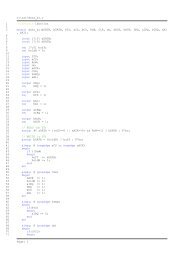
- Components List SA-012618-LI-A3<br />
- Instruments Data Sheets SA-012381-DS-A4<br />
- General Layout SA-012617-AS-A3<br />
13.1. RECOMMENDED SPARE PARTS<br />
Due to the fact that the CO2 components do not function continuosly, they manifest a low degree of<br />
wear. Therefore, with normal use and preventive maintenance carried out, protecting against corrosion<br />
and eventual mechanical damage caused by accidental impacts, the system should be reliable for a<br />
long time.<br />
However if no good operation will be found refer to:<br />
- Components List SA-012618-LI-A3<br />
- Instruments Data Sheets SA-012381-DS-A4<br />
- General Layout SA-012617-AS-A3<br />
for replace the interested instruments.<br />
Refer to relative instruction manual attached for recommended spare parts of special components.<br />
File: 08MG3847CE_R0.doc<br />
Page 29 of 29
4<br />
3<br />
2<br />
1<br />
0 03/11/2008<br />
REV DATA/DATE<br />
SANCO S.p.A.<br />
ISSUED<br />
DESCRIZIONE - DESCRIPTION<br />
Fire Protection and Safety Technology<br />
Via Ravizza, 13/A - 28066 Galliate (Novara) - Italy<br />
NUOVO PIGNONE - <strong>FIRE</strong>NZE<br />
RM<br />
AA<br />
DP<br />
DIS./DRAW CONT/CHEC'D APPROV.<br />
COMMESSA JOB<br />
CLIENTE CUSTOMER<br />
NUOVO PIGNONE<br />
TITOLO / TITLE SCALA SCALE<br />
//<br />
CODICE CODE<br />
CO2 <strong>FIRE</strong> <strong>FIGHTING</strong> SYSTEM COMPONENTS LIST<br />
SECONDO I TERMINI DI LEGGE, SANCO S.p.A.<br />
<strong>FIRE</strong> PROTECTION AND SAFETY TECHNOLOGY<br />
SI RISERVA LA PROPRIETA' DEL PRESENTE DISEGNO E<br />
NE VIETA LA PRODUZIONE O LA COMUNICAZIONE A<br />
TERZI SENZA IL PROPIO BENESTARE.<br />
THIS DRAWING IS LEGALLY EXCLUSIVE PROPERTY<br />
OF SANCO S.p.A. <strong>FIRE</strong> PROTECTION AND SAFETY<br />
TECHNOLOGY AND<br />
IT CAN NEITHER BE REPRODUCED NOR SHOWN TO<br />
THIRD PARTIES WITHOUT OUR WRITTEN ASSENT.<br />
G3847/08<br />
FOGLIO<br />
SHEET<br />
1<br />
DI<br />
OF<br />
3<br />
DISEGNO DRAWING<br />
SA-012618-LI-A3
GTG-A<br />
(MACHINE 1)<br />
GTG-B<br />
(MACHINE 2)<br />
N.P. TAG CUSTOMER TAG DESCRIPTION SERVICE EXECUTION MATERIAL CODE Q.TY RANGE SET<br />
33CP-1A ZSL-1744/A<br />
33CP-2A<br />
ZSH-1745/A<br />
33CP-1B ZSL-1744/B<br />
33CB-2B ZSH-1745/B<br />
33CR-1A ÷ 33CR-5A WSL-1740A ÷ WSL-1740E<br />
45CR-1A _ 45CR-2A FV-1741 _ FV-1742<br />
63CP-1 PSHH-1743<br />
XA-1 _ XA-2 XA-1711/A _ XA-1711/B<br />
XL-1 _ XL-2 XL-1710/A _ XL-1710/B<br />
43CPD-1 _ 43CPD-2 HS-1712/A _ HS-1712/B<br />
33CP-1C ZSL-2744/A<br />
33CP-2C ZSH-2745/A<br />
33CP-1D ZSL-2744/B<br />
33CB-2D ZSH-2745/B<br />
33CR-1B ÷ 33CR-5B WSL-2740A ÷ WSL-2740E<br />
45CR-1B _ 45CR-2B FV-2741 _ FV-2742<br />
63CP-2 PSHH-2743<br />
XA-1 _ XA-2 XA-2711/A _ XA-2711/B<br />
XL-1 _ XL-2 XL-2710/A _ XL-2710/B<br />
43CPD-1 _ 43CPD-2 HS-2712/A _ HS-2712/B<br />
MANUFACTURER<br />
MODEL<br />
LIMIT SWITCH SLOW DISCHARGE CUT-OFF VALVE - CLOSE POSITION EEx-d ZINC DIE-CAST BXC3K<br />
1<br />
ON-OFF -<br />
HONEYWELL<br />
BX Series<br />
CO2 CYLINDERS CABINET<br />
LIMIT SWITCH SLOW DISCHARGE CUT-OFF VALVE - OPEN POSITION EEx-d ZINC DIE-CAST BXC3K<br />
1<br />
ON-OFF -<br />
HONEYWELL<br />
BX Series<br />
CO2 CYLINDERS CABINET<br />
LIMIT SWITCH QUICK DISCHARGE CUT-OFF VALVE - CLOSE POSITION EEx-d ZINC DIE-CAST BXC3K<br />
1<br />
ON-OFF<br />
-<br />
HONEYWELL<br />
BX Series<br />
CO2 CYLINDERS CABINET<br />
LIMIT SWITCH QUICK DISCHARGE CUT-OFF VALVE - OPEN POSITION EEx-d ZINC DIE-CAST BXC3K<br />
1<br />
ON-OFF<br />
-<br />
HONEYWELL<br />
BX Series<br />
CO2 CYLINDERS CABINET<br />
LIMIT SWITCH CO2 CYLINDER WEIGHT DEVICE<br />
EEx-d ZINC DIE-CAST BXC3K<br />
5<br />
ON-OFF<br />
-<br />
HONEYWELL<br />
BX Series<br />
CO2 CYLINDERS CABINET<br />
SOLENOID VALVE CO2 DISCHARGE ACTUATOR<br />
EEx-d STAINLESS STEEL -<br />
2<br />
-<br />
24Vdc<br />
ATAM WINDINGS<br />
2710A100A<br />
CO2 CYLINDERS CABINET<br />
PRESSURE SWITCH CO2 DISCHARGE ACTIVATED EEx-d STAINLESS STEEL ITN66141 RPO484743030 1<br />
10÷100bar 18bar (RISING)<br />
DELTA CONTROLS CO2 CYLINDERS CABINET<br />
S21<br />
HORN AUDIBLE <strong>FIRE</strong> ALARM<br />
EEx-d LIGHT ALLOY 48.90.102.215 2<br />
-<br />
24Vdc<br />
A.E.S.<br />
ETH20MD<br />
FLASH LAMP RED LIGHT OPTICAL <strong>FIRE</strong> ALARM<br />
EEx-d LIGHT ALLOY 48.90.120.015 2<br />
- 24Vdc<br />
A.E.S.<br />
EVA200<br />
PUSH BUTTON CO2 MANUAL RELEASE<br />
(GLASS TO BE BROKEN PUSH BUTTON)<br />
EEx-d LIGHT ALLOY 48.90.500.795 2<br />
ON-OFF -<br />
COELBO<br />
EFD-1 E1<br />
LIMIT SWITCH SLOW DISCHARGE CUT-OFF VALVE - CLOSE POSITION EEx-d ZINC DIE-CAST BXC3K<br />
1<br />
ON-OFF -<br />
HONEYWELL<br />
BX Series<br />
CO2 CYLINDERS CABINET<br />
LIMIT SWITCH SLOW DISCHARGE CUT-OFF VALVE - OPEN POSITION EEx-d ZINC DIE-CAST BXC3K<br />
1<br />
ON-OFF<br />
-<br />
HONEYWELL<br />
BX Series<br />
CO2 CYLINDERS CABINET<br />
LIMIT SWITCH QUICK DISCHARGE CUT-OFF VALVE - CLOSE POSITION EEx-d ZINC DIE-CAST BXC3K<br />
1<br />
ON-OFF -<br />
HONEYWELL<br />
BX Series<br />
CO2 CYLINDERS CABINET<br />
LIMIT SWITCH QUICK DISCHARGE CUT-OFF VALVE - OPEN POSITION EEx-d ZINC DIE-CAST BXC3K<br />
1<br />
ON-OFF<br />
-<br />
HONEYWELL<br />
BX Series<br />
CO2 CYLINDERS CABINET<br />
LIMIT SWITCH CO2 CYLINDER WEIGHT DEVICE EEx-d ZINC DIE-CAST BXC3K<br />
5<br />
ON-OFF -<br />
HONEYWELL<br />
BX Series<br />
CO2 CYLINDERS CABINET<br />
SOLENOID VALVE CO2 DISCHARGE ACTUATOR EEx-d STAINLESS STEEL -<br />
2<br />
-<br />
24Vdc<br />
ATAM WINDINGS<br />
2710A100A<br />
CO2 CYLINDERS CABINET<br />
PRESSURE SWITCH CO2 DISCHARGE ACTIVATED EEx-d STAINLESS STEEL ITN66141 RPO484743030 1<br />
10÷100bar 18bar (RISING)<br />
DELTA CONTROLS CO2 CYLINDERS CABINET<br />
S21<br />
HORN AUDIBLE <strong>FIRE</strong> ALARM EEx-d LIGHT ALLOY 48.90.102.215 2<br />
-<br />
24Vdc<br />
A.E.S.<br />
ETH20MD<br />
FLASH LAMP RED LIGHT OPTICAL <strong>FIRE</strong> ALARM EEx-d LIGHT ALLOY 48.90.120.015 2<br />
- 24Vdc<br />
A.E.S.<br />
EVA200<br />
PUSH BUTTON CO2 MANUAL RELEASE<br />
(GLASS TO BE BROKEN PUSH BUTTON)<br />
EEx-d LIGHT ALLOY 48.90.500.795 2<br />
ON-OFF<br />
-<br />
COELBO<br />
EFD-1 E1<br />
LOCATION<br />
FIELD<br />
FIELD<br />
FIELD<br />
FIELD<br />
FIELD<br />
FIELD<br />
SANCO S.p.A.<br />
<strong>FIRE</strong> PROTECTION AND SAFETY TECHNOLOGY<br />
CLIENTE CUSTOMER COMMESSA JOB<br />
NUOVO PIGNONE G3847/08<br />
DISEGNO DRAWING FOGLIO<br />
SHEET 2<br />
DI<br />
OF<br />
SA-012618-LI-A3<br />
3
N.P. TAG CUSTOMER TAG DESCRIPTION SERVICE EXECUTION MATERIAL CODE Q.TY RANGE SET<br />
GTG-A + GTG-B<br />
JB-28<br />
JUNCTION BOX SOLENOID VALVES Eex-e ALLUMINIUM<br />
ALLOY<br />
ESA 2222<br />
1 - - NUOVA ASP<br />
ESA<br />
CO2 CYLINDERS CABINET<br />
JB-29<br />
JUNCTION BOX DIGITALS SIGNALS Eex-e ALLUMINIUM<br />
ALLOY<br />
ESA 3322<br />
1 - - NUOVA ASP<br />
ESA<br />
CO2 CYLINDERS CABINET<br />
- - CO2 CYLINDER VALVE - -<br />
BRASS 99.15.120.550 10 - - V.T.I.<br />
K85-11,0-S54<br />
CO2 CYLINDERS CABINET<br />
CBVF-1A÷1E<br />
CBVF-2A÷2E<br />
CO2 CYLINDER 67lt - - 34 Cr Mo 4 99.15.110.023 10 - - ZHEJIANG JINDUN CO2 CYLINDERS CABINET<br />
- - PNEUMATIC PISTON - -<br />
AISI 01.15.300.215 2 - - SANCO<br />
- - CO2 CHECK VALVE Ø3/4" - -<br />
BRASS 01.15.220.105 6 - - SANCO<br />
- - CO2 CHECK VALVE Ø3/4"<br />
WITH LATERAL CONNECTION<br />
- -<br />
BRASS 01.15.220.110 4 - - SANCO<br />
- - WEIGHTING DEVICE - - ALLUMINIUM<br />
ALLOY<br />
01.15.300.115 10 - - SANCO<br />
- - LOCKABLE CUT-OFF VALVE CO2 QUICK DISCHARGE - GALVANIZED -<br />
2 - - ADLER<br />
Ø3/4" STEEL FS2<br />
- - LOCKABLE CUT-OFF VALVE CO2 SLOW DISCHARGE - GALVANIZED -<br />
2 - - ADLER<br />
Ø1/2" STEEL FS2<br />
- - CO2 HOSE - - GALVANIZED STEEL<br />
RUBBER<br />
01.15.220.125 10 - - SANCO<br />
- - CO2 NOZZLES 1/2"<br />
(see discharge calculation)<br />
- -<br />
AISI -<br />
4 - - SANCO<br />
- - SAFETY VALVE - - CHROMIUM STEEL<br />
NODULAR CAST IRON<br />
50.15.120.215 4 - 140 bar SANCO<br />
CLIENTE CUSTOMER COMMESSA JOB<br />
NUOVO PIGNONE G3847/08<br />
DISEGNO DRAWING FOGLIO<br />
SHEET 3<br />
DI<br />
OF<br />
SA-012618-LI-A3<br />
MANUFACTURER<br />
MODEL<br />
LOCATION<br />
CO2 CYLINDERS CABINET<br />
CO2 CYLINDERS CABINET<br />
CO2 CYLINDERS CABINET<br />
CO2 CYLINDERS CABINET<br />
CO2 CYLINDERS CABINET<br />
CO2 CYLINDERS CABINET<br />
CO2 CYLINDERS CABINET<br />
ON FIELD<br />
CO2 CYLINDERS CABINET<br />
SANCO S.p.A.<br />
<strong>FIRE</strong> PROTECTION AND SAFETY TECHNOLOGY<br />
3
▲<br />
▲<br />
▲<br />
▲<br />
▲<br />
▲<br />
▲<br />
▲<br />
▲<br />
▲<br />
INSTRUMENTATION SOLUTIONS FOR INDUSTRY<br />
Ranges available up to 700 bar<br />
(10,000 psi)<br />
Maximum working pressure up to<br />
1000 bar (15,000 psi).<br />
Epoxy coated die cast and natural<br />
stainless steel weatherproof<br />
enclosures NEMA 4, 4X, IP66 and<br />
Explosionproof NEMA 4, 4X, 7,9.<br />
Safety vented design as standard.<br />
Field set point adjustment against<br />
a reference scale.<br />
SPDT or DPDT switching and<br />
optional gold alloy contacts.<br />
Terminal block for easy field wiring.<br />
Hermetically sealed microswitch<br />
options.<br />
316 stainless steel wetted parts.<br />
NACE MR-01-75 compatibility.<br />
The Sovereign Series S20 Pressure<br />
Switches are designed as compact, cost<br />
effective solutions to meet a variety of<br />
applications in the oil, gas and chemical<br />
industries.<br />
The sensing element consists of a<br />
diaphragm sealed piston providing high<br />
integrity, sensitivity and overload<br />
protection.<br />
The Sovereign Series continues to offer<br />
the high standard of performance and<br />
service so long the hallmark of Delta<br />
Controls.<br />
SOVEREIGN SERIES<br />
DIAPHRAGM OPERATED<br />
PRESSURE SWITCHES<br />
✽<br />
LISTED<br />
LISTED<br />
BASEEFA<br />
CENELEC<br />
JAPANESE APPROVAL<br />
HOW TO ORDER<br />
When ordering, please state the<br />
relevant product code for each<br />
instrument, made up as follows:<br />
Enclosure. See Table l.<br />
Model. See Table 2.<br />
Electrical Entry. See Table 3.<br />
Material of Wetted Parts. See Table 4.<br />
Range. See Table 5.<br />
Switching Options. See Table 6.<br />
Process Connection. See Table 7.<br />
Options. See Table 8.<br />
Special Engineering.<br />
By consultation with our engineers. See Table 9.<br />
ISO 9001<br />
FM 720<br />
S21/2/4<br />
ISSUE G.1
ENCLOSURES<br />
INTRINSIC SAFETY<br />
Pressure switches neither store nor<br />
generate electricity and are therefore<br />
normally usable in intrinsically safe<br />
circuits without further certification<br />
provided that the power source of the<br />
circuit is certified Exi and the installation<br />
is in accordance with the relevant<br />
codes of practice (e.g. ANSI/ISA 12.6 or<br />
BS 5345 Part 4, 1977). Because of the<br />
low voltages and currents of I.S. circuits,<br />
we recommend using gold and/or<br />
sealed contacts.<br />
Temperatures in Table 1 refer to<br />
limitations for certified enclosures. See<br />
TECHNICAL DATA.<br />
NOTE: Codes T and U - to increase gas<br />
class see Table 6.<br />
NOTE: Codes H, T for 4X<br />
Aluminium Enclosure protected by<br />
quality epoxy paint system.<br />
Performance of enclosure requires<br />
careful installation and sealing of cable<br />
gland connection in situ.<br />
Assembly requires to be built for Marine<br />
use, See Table 8, Code 02.<br />
JAPANESE APPROVAL ✽<br />
An enclosure Code `B' is available that<br />
meets the requirements of Japanese<br />
industrial standards for use in hazardous<br />
areas. Details on application.<br />
MODELS<br />
S21/2<br />
For applications up to 100 bar (1500 psi).<br />
Maximum working pressure 155 bar<br />
(2250 psi).<br />
S24<br />
For applications up to 700 bar<br />
(10,000 psi). Maximum working pressure<br />
1000 bar (15,000 psi).<br />
ELECTRICAL ENTRY<br />
Adaptors are available for other popular<br />
thread sizes.<br />
TABLE 1<br />
EXPLOSIONPROOF ENCLOSURES DIVISION 1 (ZONE 1) Code<br />
Aluminium Alloy EExd IIC T6(-60 to +65ºC), T5(-60 to +80ºC)<br />
Gravity die-cast enclosure In aluminium-silicon alloy, epoxy painted<br />
internally and externally. BASEEFA certified to CENELEC EN 50 014 H<br />
and EN 50 018. Weatherproof to NEMA type 4, 4X, IP66. See Note.<br />
For Aggressive Atmospheres EExd IIC T6(-60 to +65ºC)<br />
T5(-60 to +80ºC) Investment cast enclosure In austenitic stainless steel.<br />
BASEEFA certified to CENELEC EN 50 014 and EN 50 018. R<br />
Weatherproof to NEMA type 4X, IP66.<br />
Aluminium Alloy NEC 500, NEMA 7,9<br />
Gravity die-cast enclosure in aluminium-silicon alloy, epoxy painted<br />
internally and externally. Class 1, Groups C and D, Class II, T<br />
Groups E, F and G, Div. 1&2.Weatherproof to NEMA type 4, 4X, IP66.<br />
See Note.<br />
For Aggressive Atmospheres NEC 500, NEMA 7,9<br />
Investment cast enclosure in austenitic stainless steel.<br />
Class 1, Groups C and D, Class II, Groups E, F and G, Div. 1 & 2. U<br />
Weatherproof to NEMA type 4X, IP66.<br />
SAFE AREA ENCLOSURES<br />
General Purpose Weatherproof<br />
The basic enclosure is pressure die-cast in zinc alloy, epoxy painted, W<br />
with weather protection not less than NEMA type 4, IP66.<br />
Weatherproof For Aggressive Atmospheres<br />
Investment cast enclosure In austenitic stainless steel with A<br />
weather protection not less than NEMA type 4X, IP66.<br />
TABLE 2<br />
Code<br />
Fixed Switching Differential.<br />
SPDT & DPDT options available. See Table 6.<br />
S21<br />
Adjustable Switching Differential. (Limited Span)<br />
Achieved by special microswitch with built in adjuster. SPDT only S22<br />
See Table 6.<br />
Fixed Switching Differential.<br />
S24<br />
SPDT & DPDT options available. See Table 6.<br />
TABLE 3<br />
Enclosure W: 22mm dia (0.86 in) entry. 1<br />
Enclosure W: M20 x 1.5 elbow adaptor to suit. 0<br />
Enclosure W: 3 / 4 -NPT INT. elbow adaptor to suit. 3<br />
Enclosures H, R & A: M20 x 1.5 ISO thread. 0<br />
Enclosures H, R & A: M20 x 1.5 ISO thread, dual entry. 5<br />
Enclosures H, R, T & U: 3 / 4 -NPT INT. 3<br />
Enclosures H, R, T & U: 3 / 4 -NPT INT. dual entry 6<br />
SEE APPROVALS<br />
Code
MATERIAL OF<br />
WETTED PARTS<br />
WELDED CONSTRUCTION<br />
Code S and T.<br />
For reduced risk against leakage<br />
under extreme or unusual conditions<br />
the diaphragm may be welded directly<br />
to the process connection, eliminating<br />
the O-ring.<br />
Welded construction not available on<br />
ranges CC to CE (CW to CK). (See Table<br />
5.) Ranges CC to G3 (CW to GK)<br />
available with metallic diaphragm only.<br />
(See Table 5.)<br />
SETTING RANGES<br />
When ordering, please state units<br />
required. Range and set point will be in<br />
units of preference.<br />
1 bar = 100kPa = 14.5 psi<br />
1 mbar = 100Pa = 0.39 in.H 2 O<br />
Pmax = maximum working pressure<br />
NOTE: Codes may differ for other units.<br />
TABLE 4<br />
Code<br />
316 stainless steel diaphragm, process connection and viton<br />
O-ring seal. A<br />
316 stainless steel diaphragm, process connection and nitrile<br />
O-ring seal. G<br />
Stainless steel process connection, Polyimide (Kapton)<br />
diaphragm and nitrile O-ring seal. H<br />
Nickel Alloy (Monel) diaphragm, 316 stainless steel process<br />
connection and Viton O-ring seal, for application as laid K<br />
down in NACE MR-01-75.<br />
Nickel Alloy (Monel) diaphragm, 316 stainless steel process<br />
connection and nitrile O-ring seal. P<br />
316 stainless steel diaphragm and process connection. All<br />
welded construction. S<br />
Nickel Alloy (Monel) welded diaphragm and process<br />
connection. (Suitable for NACE MR-01-75) T<br />
APPLIES TO ALL MATERIALS IN THE TABLE ABOVE AND AVAILABLE IN A VARIETY OF<br />
COMBINATIONS<br />
TABLE 5<br />
Pmax RANGE<br />
bar psi Model bar mbar Code psi in.Hg in.H2O Code<br />
S21 12 to 250 CC 5 to 100 CW<br />
S21 -120 to +120 CD -50 to +50 CH<br />
15 217 S21 100 to 600 CE 1.5 to 8.5 CK<br />
S21 -1000 to 0 AO -30 to 0 AB<br />
S21 -1 to +1.5 G3 -14.5 to 20 GK<br />
S21/2 0.25 to 1.6 DB 4 to 25 DK<br />
27 400 S21/2 0.4 to 2.5 DC 6 to 40 DP<br />
S21/2 1 to 6 DE 16 to 100 DZ<br />
S21/2 1.6 to 10 EA 25 to 160 EH<br />
70 1000 S21/2 2.5 to 16 EB 40 to 250 EM<br />
S21/2 4 to 25 EC 60 to 400 ER<br />
110 1600 S21/2 10 to 40 ED 160 to 600 EW<br />
S21/2 16 to 75 EF 250 to 1000 EE<br />
155 2250 S21/2 10 to 100 FA 160 to 1500 F6<br />
APPLIES TO ALL RANGES IN THE TABLE ABOVE<br />
Pmax RANGE<br />
bar psi Model bar Code psi Code<br />
S24 0.4 to 2.5 DC 6 to 40 DP<br />
S24 1 to 6 DE 16 to 100 DZ<br />
S24 1.6 to 10 EA 25 to 160 EH<br />
-1 -30”Hg S24 2.5 to 16 EB 40 to 250 EM<br />
to to<br />
600 8700 S24 4 to 25 EC 60 to 400 ER<br />
S24 10 to 40 ED 160 to 600 EW<br />
S24 16 to 75 EF 250 to 1000 EE<br />
S24 10 to 100 FA 160 to 1500 F6<br />
S24 7 to 160 U7 100 to 2300 UK<br />
1000 15000 S24 25 to 250 V7 350 to 3500 VC<br />
S24 50 to 400 W7 800 to 6000 W9<br />
S24 100 to 700 Y4 1600 to 10000 YF<br />
APPLIES TO ALL RANGES IN THE TABLE ABOVE SEE APPROVALS
SWITCHING OPTIONS<br />
PROCESS<br />
CONNECTION<br />
Other thread specifications and sizes<br />
are available without using adaptors.<br />
Adaptors are available for applications<br />
where their use is permitted.<br />
TABLE 6<br />
Model S21/4<br />
IEC 947-5-1/EN 60947-5-1 RATING<br />
UL/CSA RATING<br />
(RESISTIVE)<br />
§SEE NOTE<br />
Designation &<br />
Utilization<br />
Category<br />
Rated operational current Ie (A) at rated operational<br />
voltage Ue Ui Uimp VA rating<br />
Make Break<br />
Contact Code<br />
5 Amps @ 110/250V AC<br />
Light Duty for AC only<br />
AC14<br />
DC13<br />
D300<br />
R300<br />
0.6/0.3A @ 120/240V AC<br />
0.22/0.1A @ 125/250V DC<br />
250V 0.8kV<br />
AC<br />
DC<br />
432<br />
28<br />
72<br />
28<br />
SPDT<br />
DPDT<br />
00<br />
01<br />
5 Amps @ 110/250V AC and<br />
2 Amps @ 30V DC<br />
General purpose precision<br />
AC14<br />
DC13<br />
D300<br />
R300<br />
0.6/0.3A @ 120/240V AC<br />
0.22/0.1A @ 125/250V DC<br />
250V 0.8kV AC<br />
DC<br />
432<br />
28<br />
72<br />
28<br />
SPDT<br />
DPDT<br />
02<br />
03<br />
1 Amp @ 125V AC and<br />
§100 mA @ 30V DC gold alloy<br />
contacts for low voltage switching<br />
1A @ 125 VAC RESISTIVE (IEC 1058-1/EN 61058-1)<br />
SPDT<br />
DPDT<br />
04<br />
05<br />
§5 Amps @ 110/250V AC and<br />
5 Amps @ 30V DC<br />
Environmentally sealed<br />
AC14<br />
DC13<br />
D300<br />
R300<br />
0.6/0.3A @ 120/240V AC<br />
0.22/0.1A @ 125/250V DC<br />
250V 0.5kV AC<br />
DC<br />
432<br />
28<br />
72<br />
28<br />
SPDT*<br />
DPDT*<br />
08<br />
09<br />
§1 Amp @ 30V AC and<br />
30V DC Environmentally sealed<br />
with gold contacts<br />
AC14 E150 0.3A @ 120V AC 125V 0.5kV AC 216 36<br />
TABLE 7<br />
SPDT* 0G<br />
DPDT* 0H<br />
5 Amps @250V AC and<br />
2 Amps @ 30V DC Hermetically<br />
sealed. Gold plated silver contacts<br />
AC14<br />
DC13<br />
D300<br />
R300<br />
0.6/0.3A @ 120/240V AC<br />
0.22/0.1A @ 125/250V DC<br />
250V 0.5kV AC<br />
DC<br />
432<br />
28<br />
72<br />
28<br />
SPDTt<br />
DPDTt<br />
H2<br />
H3<br />
†<br />
, H66<br />
‡<br />
†2 Single pole, double throw. simultaneous falling under pressure.<br />
‡2 Single pole, double throw, simultaneous rising under pressure.<br />
Model S22<br />
5 Amps @ 110/250V AC<br />
Adjustable for AC only<br />
AC14 D300 0.6/0.3A @ 120/240V AC 250V 0.8kV AC 432 72 SPDT 0C<br />
5 Amps @ 110/250V AC and<br />
2 Amps @ 30V DC Adjustable<br />
AC14<br />
DC13<br />
D300<br />
R300<br />
0.6/0.3A @ 120/240V AC<br />
0.22/0.1A @ 125/250V DC<br />
250V 0.8kV<br />
AC<br />
DC<br />
432<br />
28<br />
72<br />
28<br />
SPDT 0D<br />
NOTE: Enclosure Codes T and U. Enclosure Codes H and R.<br />
Microswitch Codes 02 and 03. Microswitch Codes 02 and 03.<br />
UL/CSA rating as follows:- UL/CSA Rating as follows:-<br />
110/150V AC 5A 250V/125V DC 0.25/0.5A 110/250V AC 5A 250V/125/30V DC 0.25/0.5/2A<br />
NOTE: Using Codes H2, H3, H6 increases the Gas Class to:<br />
Class 1, Groups A, B, C and D, Div 2., for Enclosures T and U.<br />
UL recognised component for use in hazardous areas. CSA accepted component for use in hazardous<br />
Class 1, Div 2, Groups A,B,C and D. Class II Groups F areas Class 1, Div 2, Groups A,B,C and D.<br />
and G. When used in enclosures T and U. When used in enclosures T and U.<br />
The electrical rating is dependent on the microswitch fitted to the instrument. The electrical ratings defined by each approval that the micro<br />
switch complies with and is shown on the product nameplate, ie UL/CSA, or IEC. It should be noted that the instrument must be used within the<br />
electrical rating specified from the approval you require. This table lists the actual IEC ratings against the Designation& Utilization Category<br />
marked on the nameplates. In the absence of any verification by UL/CSA the microswitch §manufacturer's rating is stated in italics and bold.<br />
If in doubt seek guidance from the factory.<br />
Code<br />
Rc 1 / 4 ( 1 / 4 BSP tr INT) to BS21 (ISO 7/1) A<br />
1 /4 -18NPT INT F<br />
1 /2 -14NPT INT H<br />
1 /2 -14NPT EXT J
OPTIONS AND<br />
TREATMENTS<br />
Combinations available, apply for details.<br />
SPECIAL ENGINEERING<br />
To your individual requirements, where<br />
specified. For your convenience, enter<br />
your special listing in space provided.<br />
PERFORMANCE DATA<br />
TABLES 10A, 10B, 10C, 10D.<br />
MODELS S21, S24<br />
FIXED SWITCHING DIFFERENTIAL<br />
TABLE 8<br />
TABLE 9<br />
RANGE Pmax<br />
SWITCHING OPTIONS.<br />
SWITCHING DIFFERENTIAL in H2O/inHg/PSI Code H2O/inHg/PSI PSI 00 01 02 03 04 05 08/0G 09/0H H2 H3/6<br />
CW 5 to 100 218 2 3.1 3.5 5.5 2 2.4 3.1 6 11.7 11.7<br />
CH -50 to +50 218 3.1 5.5 3.1 9 3.1 3.1 5.5 7 8 8<br />
CK 1.5 to 8.5 218 3.1 5.5 6 9 3.1 4.7 5.5 7 18 18<br />
AB -30 to 0 218 0.6 0.8 1.3 1.7 0.5 0.5 0.8 1 3 3<br />
GK -14.5 to +20 218 0.3 0.6 0.7 1.5 0.3 0.4 0.5 0.7 2.2 2.2<br />
DK 4 to 25 400 0.4 0.7 1.0 1.5 1.0 1.5 2.6 3.5 1.2 2.3<br />
DP 6 to 40 400 0.4 0.7 1.0 1.5 1.0 1.5 2.6 3.5 1.2 2.3<br />
DZ 16 to 100 400 0.6 0.9 1.7 2.0 1.5 2.2 3.5 1.6 2.9 5.8<br />
EH 25 to 160 1000 1.5 2.2 3.6 6.5 2.2 3.3 11.6 14.5 6 11.6<br />
EM 40 to 250 1000 2.2 4.0 5.1 9.9 3.6 5.8 13.1 17.4 7.5 14.5<br />
ER 60 to 400 1500 4.4 6.5 15.2 19.6 7.3 10.2 26 35 26 52<br />
EW 160 to 600 1500 7.3 11.6 20 26 11.6 17.4 44 46 31 61<br />
EE 250 to 1000 1500 9.4 14.5 25 33 14.5 22 44 58 51 102<br />
F6 160 to 1500 2250 14.5 22 51 65 29 44 87 116 73 145<br />
SWITCHING OPTIONS.<br />
RANGE Pmax SWITCHING DIFFERENTIAL PSI<br />
Code PSI PSI 00 01 02 03 04 05 08/0G 09/0H H2 H3/6<br />
DP 6 to 40 8700 3.2 4.8 5.8 5.8 4.4 4.4 6.5 7.4 6 11.6<br />
DZ 16 to 100 8700 3.5 5.8 8.7 11.6 7.3 10.2 8.7 9.4 12 23<br />
EH 25 to 160 8700 5.5 10.2 11.6 17.4 8.7 13 8.7 11 18 35<br />
EM 40 to 250 8700 6.7 11.5 11.6 17.4 8.7 13 11.6 17.4 18 35<br />
ER 60 to 400 8700 12.5 20 17.4 23 11.6 17.4 20 22 34 67<br />
EW 160 to 600 8700 14.5 23 29 44 22 36 29 44 51 102<br />
EE 250 to 1000 8700 22 28 36 73 22 58 44 58 58 116<br />
F6 160 to 1500 8700 29 36 65 87 51 73 58 73 73 145<br />
UK 100 to 2300 15000 49 80 99 145 58 77 73 90 150 290<br />
VC 350 to 3500 15000 81 162 145 244 122 203 725 870 370 725<br />
W9 800 to 6000 15000 128 255 255 574 192 319 1160 1160 600 1160<br />
YF 1600 to 10000 15000 218 435 290 653 326 486 1450 1450 750 1450<br />
Code<br />
Tropicalisation High humidity environment. 01<br />
Marine and Offshore Saline atmosphere or salt spray. 02<br />
Ammonia Process (wetted) parts and construction suitable<br />
for atmospheric ammonia.<br />
Oxygen Service 2: Process (wetted) parts are cleaned for oxygen.<br />
Oxygen Service 3: Process and non process parts are<br />
cleaned for use with oxygen.<br />
Stainless Steel Pipe Mounting Bracket Permits local 2" pipework to<br />
be utilised for mounting the instrument.<br />
Tagging - Variety of tagging methods are available<br />
Applies when - no option is required and selection is<br />
made from special engineering<br />
FEATURE Code<br />
TABLE 10<br />
APPLIES TO ALL OPTIONS AND TREATMENTS IN TABLE ABOVE<br />
SEE APPROVALS<br />
Figures given in Table 10 are typical<br />
maxima for mid-range setting and are<br />
for guidance only. Values will vary across<br />
the range, i.e. lower at the bottom and<br />
APPLY FOR<br />
DETAILS<br />
higher at the top of the range. Should<br />
the differential be critical for specific<br />
applications our engineers should be<br />
consulted prior to ordering.<br />
MODEL S21 PSI UNITS TABLE 10A MODEL S21 SI UNITS TABLE 10B<br />
SWITCHING OPTIONS.<br />
RANGE Pmax SWITCHING DIFFERENTIAL mbar<br />
Code mbar/bar bar 00 01 02 03 04 05 08/0G 09/0H H2 H3/6<br />
CC 12 to 250 16 5 8 6 8 5 6 8 15 30 30<br />
CD -120 to 120 16 8 14 8 23 8 8 14 18 20 20<br />
CE 100 to 600 16 8 14 15 23 8 12 14 18 45 45<br />
A0 -1000 to 0 16 21 27 45 60 18 18 30 36 105 105<br />
G3 -1 to +1.5 16 21 40 48 100 24 30 36 45 150 150<br />
DB 0.25 to 1.6 27 30 45 70 100 70 100 180 240 80 160<br />
DC 0.4 to 2.5 27 30 45 70 100 70 100 180 240 80 160<br />
DE 1 to 6 27 40 60 120 140 100 150 240 320 200 400<br />
EA 1.6 to 10 70 100 150 250 450 150 230 800 100 400 800<br />
EB 2.5 to 16 70 150 275 350 680 250 400 900 1200 500 1000<br />
EC 4 to 25 112 300 450 1050 1350 500 700 1800 2400 1800 3600<br />
ED 10 to 40 112 500 800 1400 1800 800 1200 3000 3200 2100 4200<br />
EF 16 to 75 112 650 1000 1750 2250 1000 1500 3000 4000 3500 7000<br />
FA 10 to 100 155 1000 1500 3500 4500 2000 3000 6000 8000 5000 10000<br />
MODEL S24 TABLE 10C MODEL S24 TABLE 10D<br />
SWITCHING OPTIONS.<br />
RANGE Pmax SWITCHING DIFFERENTIAL mbar<br />
Code bar bar 00 01 02 03 04 05 08/0G 09/0H H2 H3/6<br />
DC 0.4 to 2.5 600 220 330 400 400 300 300 450 510 400 800<br />
DE 1 to 6 600 240 400 600 800 500 700 600 650 800 1600<br />
EA 1.6 to 10 600 380 700 800 1200 600 900 600 750 1200 2400<br />
EB 2.5 to 16 600 480 790 800 1200 600 900 800 1200 1200 2400<br />
EC 4 to 25 600 860 1400 1200 1600 800 1200 1350 1500 2300 4600<br />
ED 10 to 40 600 1000 1600 2000 3000 1500 2500 2000 3000 3500 7000<br />
EF 16 to 75 600 1500 1900 2500 5000 1500 4000 3000 4000 4000 8000<br />
FA 10 to 100 600 2000 2500 4500 6000 3500 5000 4000 5000 5000 10000<br />
U7 7 to 160 1000 3400 5500 6800 10000 4000 5300 5000 6200 10000 20000<br />
V7 25 to 250 1000 5600 11200 10000 16800 8400 14000 50000 60000 35000 50000<br />
W7 50 to 400 1000 8800 17600 17600 39600 13200 22000 80000 80000 40000 80000<br />
Y4 100 to 700 1000 15000 30000 20000 45000 22500 33500 100000 100000 50000 100000<br />
TABLES 10E, 10F. MODEL S22 ADJUSTABLE SWITCHING DIFFERENTIAL<br />
MODELS S22 TABLE 10E MODEL S22 TABLE 10F<br />
SWITCHING OPTIONS.<br />
SWITCHING OPTIONS.<br />
RANGE Pmax SWITCHING DIFFERENTIAL PSI<br />
RANGE Pmax SWITCHING DIFFERENTIAL mbar<br />
Code PSI PSI MIN OC MAX MIN OD MAX Code bar bar MIN OC MAX MIN OD MAX<br />
DK 4 to 25 400 0.2 1.1 1.0 2.9<br />
DB 0.25 to 1.6 27 11 78 66 200<br />
DP 6 to 40 400 0.3 1.2 1.3 3.0<br />
DC 0.4 to 2.5 27 22 82 88 210<br />
DZ 16 to 100 400 0.5 2.8 2.5 7.3<br />
DE 1 to 6 27 33 190 170 500<br />
EH 25 to 160 1000 1.9 6.2 6.4 16<br />
EA 1.6 to 10 70 132 430 440 1100<br />
EM 40 to 250 1000 3.2 9.1 9.6 23<br />
EB 2.5 to 16 70 220 630 660 1600<br />
ER 60 to 400 1500 9.6 35 41 88<br />
EC 4 to 25 112 660 2400 2800 6100<br />
EW 160 to 100 1500 13 61 57 125<br />
ED 10 to 40 112 880 3300 3900 8600<br />
EE 250 to 1000 1500 16 62 80 160<br />
EF 16 to 75 112 1100 4300 5500 11000<br />
F6 160 to 1500 2250 25 83 96 212<br />
FA 10 to 100 155 1700 5700 6600 14600<br />
03<br />
04<br />
05<br />
10<br />
00
TECHNICAL DATA<br />
ACCURACY<br />
Set point repeatability ±1% of span at<br />
20ºC ambient.<br />
AMBIENT TEMPERATURE RANGE<br />
All models are suitable for operating<br />
within a range of -25 to +60ºC (-13 to<br />
+140ºF). Enclosures A, H, R, T, U, on<br />
Models S21 and S24 with ranges CC to<br />
FA may be used intermittently down to<br />
-60 and up to +80ºC (-76 to +176ºF).<br />
For continuous use below -25ºC (-13ºF)<br />
we recommend using only enclosures<br />
H, R, T, U and A with special gaskets<br />
and limited switching.<br />
MAXIMUM PROCESS TEMPERATURE<br />
Subject to appropriate installation<br />
practice, the component parts<br />
withstand up to +60ºC (+140ºF). For<br />
process temperatures up to +120ºC<br />
(+248ºF), order WETTED PARTS Code A<br />
(Table 4), and for higher temperatures,<br />
refer to SPECIAL ENGINEERING.<br />
CAUTION:<br />
Moving parts have been treated with a<br />
water repelling lubricant before leaving<br />
factory.<br />
Occasional inspection and the<br />
application of a water repelling<br />
lubricant Is recommended to ensure<br />
moving parts remain free under all<br />
conditions.<br />
WARNING: Does not apply to Oxygen<br />
ELECTRICAL CONNECTIONS<br />
Terminal block<br />
Cable entry is to a non-pinching<br />
terminal block made of a nonhygroscopic<br />
thermosetting plastic,<br />
suitable for cables up to<br />
2.5mm 2 /14AWG.<br />
Earthing/Grounding<br />
An earthing facility is provided.<br />
Dielectric Strength<br />
The electrical assembly is capable of<br />
withstanding *2kV between live parts<br />
and earth/ground and 500V between<br />
open contacts.<br />
*1.2kV for microswitch Codes H2, H3<br />
and H6. Refer to Table 6.<br />
Electrical Entry<br />
Standard options are listed In Table 3.<br />
Pg, and ET threads can be<br />
accommodated by adaptors. Dual<br />
entry available in some enclosures. See<br />
Table 3.<br />
UNIT WEIGHTS (Approx)<br />
RANGE AND MODEL<br />
S21/2 S24<br />
Services, see Table 8. Enclosures CC ALL<br />
CD OTHER ALL<br />
CE RANGES RANGES<br />
B, H & T 3.5kg/7.7lb 2.7kg/5.9lb 2.8kg/6.1lb<br />
OPERATION/<br />
INSTALLATION<br />
Mounting Position/Location/<br />
Installation<br />
Vertical as shown, taking care to<br />
avoid siting in locations that transmit<br />
excessive shock or vibration. For<br />
further advice contact our<br />
engineers.<br />
TYPICAL INTERNAL ARRANGEMENT<br />
OPTIONAL EXTRAS<br />
Chemical Seals<br />
Chemical seals of our own or proprietary<br />
manufacture can be fitted when<br />
required.<br />
U & R 6.6kg/14.5lb 5.8kg/12.8lb 5.9kb/13lb<br />
W 3.1kg/6.8lb 2.6kg/5.7lb 2.9kg/6.4lb<br />
A 4.2kg/9.2lb 3.8kg/8.4lb 4kg/8.8lb
APPROVALS<br />
CENELEC/BASEEFA<br />
BASEEFA certified to CENELEC EN50 014 and EN50 018.<br />
for use in Zone 1 hazardous areas.<br />
Enclosure Codes H and R and all models.<br />
BASEEFA No. Ex 89C 1374<br />
CANADIAN STANDARDS ASSOCIATION<br />
Switches - Automatic - Pressure Type - For hazardous locations<br />
Enclosure codes T & U<br />
Class 1 Groups C & D, Class II Groups E F and G<br />
LR 94185-2<br />
UNDERWRITERS LABORATORIES INC.<br />
NOWT<br />
Float - and Pressure - Operated Motor Controller<br />
For Use in Hazardous Locations.<br />
E134197(N)<br />
Enclosure codes T & U<br />
Class 1. Groups C and D, Class II, Groups E, F and G.<br />
✽<br />
JAPANESE APPROVAL<br />
BASEEFA certified to CENELEC EN50 014 and EN50 018<br />
for use in Zone 1 hazardous areas.<br />
Enclosure Code B.<br />
JAPANESE APPROVAL No. C11348.
DIMENSIONS<br />
‘B’, ‘H’, ‘R’, ‘T’, ‘U’ ENCLOSURE 'W' ENCLOSURE<br />
ALL DIMENSIONS mm (inches) ALL DIMENSIONS mm (inches)<br />
'A' ENCLOSURE MODEL S21/2 ALL RANGES CC, CD, CE<br />
ALL DIMENSIONS mm (inches)<br />
MODEL S21/2 RANGES CC, CD, CE MODEL S24 ALL RANGES<br />
ALL DIMENSIONS mm (inches)<br />
DELTA CONTROLS LIMITED, ISLAND FARM AVENUE, WEST MOLESEY, SURREY KT8 2UZ<br />
TEL: +44 (0)20 8939 3500 FAX: +44 (0)20 8783 1163<br />
E-MAIL: sales@delta-controls.com WEB SITE: www.delta-controls.com<br />
STOCK NO: 002521/S20 - Nov '00<br />
Registered Office Registered in England No. 486464<br />
ALL DIMENSIONS mm (inches)<br />
ALL DIMENSIONS mm (inches)<br />
In the interest of development and improvement Delta Controls Ltd, reserve the right to amend, without notice, details contained in this publication.<br />
No legal liability will be accepted by Delta Controls Ltd for any errors, omissions or amendments.
GENERAL<br />
The unit is manufactured, checked and supplied in<br />
accordance with our published specification, and when<br />
installed and used in normal or prescribed<br />
applications, with the lid in place and within the<br />
parameters set for mechanical and electrical<br />
performance, will not cause danger or hazard to life or<br />
limb.<br />
HEALTH AND SAFETY AT WORK ACT 1974<br />
WARNINGS<br />
1. THE USERS ATTENTION IS DRAWN TO THE<br />
FACT THAT, WHEN THE UNIT IS ‘LIVE’ WITH<br />
RESPECT TO ELECTRICAL OR PRESSURE<br />
SUPPLIES, A HAZARD MAY EXIST IF THE<br />
UNIT IS OPENED OR DISMANTLED.<br />
2. UNITS MUST BE SELECTED AND INSTALLED<br />
BY SUITABLY TRAINED AND QUALIFIED<br />
PERSONNEL IN ACCORDANCE WITH<br />
APPROPRIATE CODES OF PRACTICE SO<br />
THAT THE POSSIBILITY OF FAILURE<br />
RESULTING IN INJURY OR DAMAGE CAUSED<br />
BY MISUSE OR MISAPPLICATION IS<br />
AVOIDED.<br />
OPERATING PRINCIPLES<br />
Process pressure is sensed by a diaphragm that<br />
generates a force proportional to the applied pressure.<br />
This force is opposed by an adjustable spring which, at<br />
the point of equilibrium permits movement of an<br />
operating rod which actuates a switch or switches.<br />
Note: Should the diaphragm fail the process will vent<br />
to atmosphere via a control orifice without pressurising<br />
the switch enclosure.<br />
INSTALLATION<br />
The instruments are designed to be mounted vertically<br />
with the process connection underneath. However,<br />
mounting up to 45° from the vertical in any plane is<br />
acceptable, although a small calibration shift may<br />
occur. They can be mounted either direct to process,<br />
or to a wall or panel using the four mounting holes<br />
provided. Select the mounting point so as to avoid<br />
excessive shock, vibration or temperature fluctuation.<br />
Instruments should be mounted to avoid excessive<br />
heat transfer from the process lines or adjacent plant.<br />
To avoid undue stresses being imparted to the<br />
instrument when wall / panel mounted, it is<br />
recommended that a short length of flexible line be<br />
installed between the instrument and process line.<br />
Take care to select and install adaptors to the<br />
electrical entry that do not reduce the enclosure<br />
degree of protection.<br />
NOTE: Enclosure Codes H, T & B for NEMA 4X<br />
use.<br />
To ensure performance of enclosure, careful<br />
installation and sealing of cable gland in situ is<br />
required.<br />
On enclosures H, R, T, B and U, remove the lid using<br />
an appropriate tool if tight eg edge of spanner or metal<br />
rod (fig 2).<br />
WIRING Fig 1A Enclosures H, R, T, U, B<br />
NC<br />
SPDT<br />
REAR FRONT<br />
2 x SPDT<br />
NC = NORMALLY CLOSED<br />
COM = COMMON<br />
NO = NORMALLY OPEN<br />
BLUE<br />
SPDT<br />
RED<br />
NC<br />
NC = NORMALLY CLOSED<br />
COM = COMMON<br />
NO = NORMALLY OPEN<br />
REAR<br />
SWITCH<br />
WIRING Fig 1B Enclosures W, A<br />
RED<br />
2 x SPDT<br />
NC<br />
BLUE<br />
FRONT<br />
SWITCH<br />
FIG 1B<br />
To remove lid on enclosures H, R, T, U, B<br />
loosen lid locking device (see fig 8). Where lid<br />
is tight use a flat bar, refer to recommended<br />
sizes below. Material needs to be hard chrome<br />
steel spanner grade.<br />
The edge of a spanner may be used.<br />
7 (0.27)<br />
FIG 2<br />
R 3.5 (0.13)<br />
300 (11.8)<br />
MIN<br />
ISO 9001<br />
FM 720<br />
ALL Dimensions mm (inches)<br />
FIG 1A<br />
INSTALLATION, OPERATING AND<br />
MAINTENANCE INSTRUCTIONS FOR<br />
DIAPHRAGM ACTUATED SERIES S20<br />
SOVEREIGN PRESSURE SWITCHES<br />
(MODELS S21, S22, S24)<br />
PRODUCT CODE<br />
ENCLOSURE<br />
MODEL<br />
ELECTRICAL ENTRY<br />
MATERIAL OF WETTED PARTS<br />
RANGE<br />
SWITCHING OPTIONS<br />
PROCESS CONNECTION<br />
OPTIONS AND TREATMENTS<br />
SPECIAL ENGINEERING<br />
ISSUE J 04/00<br />
Use a spanner to support the process connection<br />
when fitting the instrument. When fitting the<br />
instrument lid make sure the ‘O’ ring is in good<br />
condition and fitted correctly.<br />
On enclosures H, R, T, U, B remove the lid using an<br />
appropriate tool if tight eg edge of a spanner or metal<br />
rod (see fig 2).<br />
WARNING: CHECK THE CONNECTION THREAD<br />
SIZE AND SPECIFICATION ON THE UNIT TO AVOID<br />
MIS-MATCHING WITH THE PROCESS<br />
CONNECTION ADAPTOR. SEE DIGIT 11 OF<br />
PRODUCT CODE.<br />
Wire in accordance with local and National codes.<br />
Use cables no larger than 2.5 mm2 (14 AWG). Deliver<br />
electrical connection through a suitable cable gland<br />
ENCLOSURES<br />
H, R, T, U & B<br />
SET POINT<br />
LOCK<br />
FIG 3<br />
COM<br />
NO<br />
MIN<br />
MAX<br />
IN<br />
ASE<br />
ENCLOSURES W & A<br />
SET POINT<br />
ADJUSTER<br />
FIG 4<br />
MA<br />
X<br />
COM<br />
SET POINT<br />
LOCK<br />
EARTH / GROUND<br />
SET POINT<br />
ADJUSTER<br />
EARTH / GROUND<br />
ADJUSTABLE MICROSWITCH MODEL S22<br />
ADJUST SWITCHING<br />
DIFFERENTIAL<br />
FIG FIG. 5 4<br />
which will maintain the IP rating of the instrument.<br />
Insert bare wires fully into the terminal block and<br />
tighten securely. Keep wiring tails to a minimum and<br />
check that wires do not interfere with the operating<br />
mechanism. Use the earthing / grounding points<br />
provided.<br />
CERTIFIED ENCLOSURES<br />
All series S20 pressure switches can be supplied with<br />
enclosures for use in hazardous areas to the following<br />
standards:<br />
Zone 1 (Div 1) IEC 79-1<br />
BS 5501: Parts 1 and 5: EN50 014 and EN50 018<br />
CENELEC. Codes ‘H’ for aluminium EEx d IIC T6,<br />
and ‘R’ for stainless steel EExd IIC T6.<br />
DIV 1 (NEC 500)<br />
Class I Groups C and D, Class II Groups E, F and G.<br />
Codes ‘T’ for aluminium and ‘U’ for stainless steel.<br />
The above mentioned enclosures are suitable for<br />
outdoor use rated IP 66 / NEMA 4. Only operation,<br />
maintenance or repair procedures either contained<br />
herein or approved by Delta Controls may be used, to<br />
avoid rendering the equipment unsafe in operation<br />
and/or nullifying the Certification. NO<br />
MODIFICATIONS ARE PERMITTED.<br />
Japanese Zone 1.<br />
Same as CENELEC Zone 1 IEC 79 with additional<br />
label and alternative terminal arrangement. Code ‘B’<br />
for aluminium IIC T6. Refer to appropriate Japanese<br />
standards for guidance on installation and use.<br />
Electrical Adaptors<br />
Use only certified adaptors for Zone 1/Div 1.<br />
WARNING: IT IS A REQUIREMENT OF SAFETY<br />
THAT AT LEAST 5 FULL THREADS ARE ENGAGED<br />
BETWEEN THE ADAPTOR AND CONDUIT ENTRY.<br />
References for Selection and Installation<br />
BS 5345 Part 3 for Enclosure Codes H and R.<br />
BS 5501 Part 1 for Enclosure Codes H and R.<br />
BS 5490 IEC 529 IP RATING (Ingress Protection)<br />
NEC ARTICLE 500 for Enclosure Code T and U.<br />
MAINTENANCE<br />
Inspections should be carried out at quarterly to yearly<br />
intervals depending upon operating conditions.<br />
Isolate the unit from process and power and remove<br />
the lid. Check all terminals for tightness. Check that<br />
cable tails are not fouled or chafed. Check for internal<br />
condensation. Rectify as necessary.<br />
It is recommended that instruments used to provide an<br />
alarm are operated periodically to ensure they are<br />
functioning correctly.<br />
If further maintenance is required seek advice from<br />
DELTA CONTROLS before attempting repair or<br />
replacement of parts.<br />
CAUTION<br />
Moving parts have been treated with a water repelling<br />
lubricant before leaving the factory. Occasional<br />
inspection and the application of a water repelling<br />
lubricant is recommended to ensure moving parts<br />
remain free under all conditions.<br />
DIM A<br />
CENTRES<br />
TYPE S21/2<br />
TYPE S24<br />
7<br />
(0.27)<br />
174 (6.85)<br />
154 (6.06)<br />
FIXING CENTRES<br />
PROCESS<br />
CONN<br />
Rc ¼<br />
¼”NPT INT<br />
36 (1.41)<br />
½”NPT INT<br />
½”NPT EXT<br />
48 (1.88)<br />
Rc ¼<br />
¼”NPT INT<br />
½”NPT INT<br />
½”NPT EXT<br />
M4 EARTH SCREW<br />
DIM A<br />
33 (1.29)<br />
45 (1.77)<br />
60 (2.36)<br />
ELECTRICAL<br />
ENTRY<br />
PROCESS<br />
CONNECTION<br />
50<br />
FIXING<br />
CENTRES<br />
95 (3.74)<br />
41<br />
(1.61)<br />
51 (2)<br />
W ENCLOSURE<br />
TYPE S21/2<br />
TYPE S24<br />
FIG 6<br />
100 (3.93)<br />
FIXING CENTRES<br />
PROCESS<br />
CONN<br />
Rc ¼<br />
¼”NPT INT<br />
36 (1.41)<br />
½”NPT INT<br />
½”NPT EXT<br />
48 (1.88)<br />
Rc ¼<br />
¼”NPT INT<br />
½”NPT INT<br />
½”NPT EXT<br />
DIM A<br />
33 (1.29)<br />
45 (1.77)<br />
60 (2.36)<br />
WARNING: DOES NOT APPLY TO OXYGEN<br />
SERVICE.<br />
Zone 1 Enclosure (H, R, T, U, B)<br />
Thread seal and contact surfaces must be lightly<br />
lubricated using a non-setting non-corrosive grease<br />
compatible with the lid seal. Do not use copper<br />
bearing grease. Screw on lid hand tight making sure<br />
that mating surfaces of the lid and enclosure are in<br />
contact. Re-tighten the lid lock screw.<br />
WARNING: IT IS A SAFETY REQUIREMENT THAT<br />
AT LEAST 5 FULL THREADS ARE ENGAGED WHEN<br />
THE UNIT IS IN OPERATION. NEVER OPERATE<br />
THE UNIT UNLESS THIS CONDITION IS MET. DO<br />
NOT USE GREASES OR LUBRICANTS NOT<br />
COMPATIBLE WITH THE ENVIRONMENT OR<br />
PROCESS.<br />
Weather-proof Enclosure (W)<br />
If lid gasket is dried out or damaged, replace with new<br />
greased gasket. Make sure gasket aligns correctly<br />
with sealing faces.<br />
Stainless Steel Weather-proof Enclosure (A)<br />
Check gasket. If damaged, replace.<br />
OPERATION<br />
Pressure switches are supplied calibrated against<br />
falling pressure unless otherwise specified. Set Point<br />
adjustment refers to falling pressure. Switching<br />
differential is the difference between the set point and<br />
the operating value on rising pressure. For opening<br />
details see Figs 2, 6, 7, 8.<br />
Set Point Adjustment: Models S21, S22 (Figs 3, 4)<br />
1. Isolate the instrument from the process and power.<br />
2. Loosen lid lock screw and remove the lid.<br />
3. Retain in a safe place to avoid damage to threads.<br />
4. Slacken the set point lock screw.<br />
5. Rotate the set point adjuster screw as required.<br />
Rotate clockwise to increase the set point and counterclockwise<br />
to decrease the set point.<br />
6. Tighten the set point lock screw.<br />
7. Replace the instrument lid (see maintenance).<br />
Switching Differential Adjustment: Models S22<br />
(Figs 3, 4, 5)<br />
1. Isolate the instrument from process and power.<br />
2. Loosen lid lock screw and remove the lid.<br />
3. Retain in a safe place to avoid damage to threads.<br />
4. Rotate the knurled plastic wheel on the microswitch<br />
to adjust the switching differential. Rotate clockwise to<br />
increase differential and counter-clockwise to reduce<br />
differential.<br />
Note: Rotating the knurled plastic wheel will alter the<br />
operating value on rising pressure only.<br />
5. Replace the instrument lid (see maintenance).<br />
Note: For accurate setting, a suitable pressure gauge<br />
must be used in conjunction with the above procedure.<br />
Do not attempt to set the switch outside the scale<br />
limits. Though the unit may be set anywhere within its<br />
operation range, for optimum performance, it is good<br />
practice to have a set point value between 25% and<br />
75% of span.<br />
CENTRES<br />
ELECTRICAL<br />
ENTRY<br />
7<br />
(0.27)<br />
TYPE S21/2<br />
TYPE S24<br />
ROTATE TO REMOVE<br />
M5 EARTH<br />
FACILITY<br />
MOUNTING HOLES<br />
8 mm (0.31) DIA<br />
LID LOCKING SET SCREW (M4)<br />
LOOSEN TO REMOVE LID<br />
PROCESS CONNECTION<br />
174 (6.85)<br />
154 (6.06)<br />
FIXING CENTRES<br />
PROCESS<br />
CONN<br />
DIM A<br />
. Rc ¼<br />
¼”NPT INT<br />
36 (1.41)<br />
½”NPT INT<br />
½”NPT EXT<br />
48 (1.88)<br />
Rc ¼<br />
¼”NPT INT<br />
½”NPT INT<br />
½”NPT EXT<br />
40<br />
(1.57)<br />
M4 EARTH SCREW<br />
33 (1.29)<br />
45 (1.77)<br />
60 (2.36)<br />
H, R, T, U, B ENCLOSURE<br />
ELECTRICAL<br />
ENTRY<br />
PROCESS<br />
CONNECTION<br />
* ADD 12mm (0.47) FOR TYPE S21/2 RANGES CC, CD, CE ONLY SPACERS SUPPLIED LOOSE<br />
140 (5.51)<br />
In the interest of development and improvement Delta Controls Ltd, reserve the right to amend without notice, details<br />
contained in this publication. No legal liability will be accepted by Delta Controls Ltd, for any errors, omissions or amendments.<br />
INSTRUMENTATION SOLUTIONS FOR INDUSTRY<br />
DELTA CONTROLS LIMITED, ISLAND FARM AVENUE, WEST MOLESEY, SURREY KT8 2UZ<br />
TEL. +44 (020) 8939 3500 FAX. +44 (020) 8783 1163 E-MAIL:sales@delta-controls.com<br />
Registered Office Registered in England No 486464<br />
125 *(4.92)<br />
56 *(2.2)<br />
*<br />
FIG 8<br />
103 (4.05)<br />
45 (1.77)<br />
53 (2.08)<br />
A ENCLOSURE<br />
FIG 7<br />
Stock No: 002522/S21
Low Voltage Directive (LVD) – 73/23/EC Amended by 93/68/EEC. Switch products with<br />
enclosure codes ‘W’ and ‘A’ supplied CE-marked must be installed and used in accordance<br />
with the main instructions and this addendum supplied with each product. Products rated lower<br />
than 50V ac and 75 V dc are outside the scope of the LVD, and therefore, do not require CEmarking<br />
under this directive. The LVD does not apply to products with enclosure codes ‘H’, ‘K’,<br />
‘R’, ‘M’, ‘N’ for use in hazardous areas. Switch products with enclosure codes ‘H’, ‘K’, ‘R’, ‘M’,<br />
‘N’, are covered by the Explosive Atmospheres Directive ATEX – 94/9/EC and when CEmarked<br />
will indicate compliance with this directive alone. The following directives do not apply<br />
to switch products manufactured by Delta Controls:<br />
Electromagnetic Compatibility EMC – 89/336/EEC amended by 93/68/EEC.<br />
Machinery Safety Directive MSD – 89/392/EEC amended by 93/68/EEC.<br />
WIRING<br />
ENCLOSURE ‘W’<br />
Cable Glands and adaptors – If enclosure ‘W’ is supplied with a through hole of 22 mm<br />
blanked with a blind grommet. Discard the grommet and fit a suitable proprietary brass or<br />
nylon M20 cable gland with thread length of 10 mm and locknut. Fit the nylon reducer provided<br />
to the inside and a fibre washer to the outside. See diagram 1.<br />
Alternately, the enclosure may be supplied from the factory with a threaded adaptor ready to<br />
accept the customer’s gland or conduit system.<br />
Alternatives:<br />
i) a metal or nylon adaptor may be used to accommodate other sizes of gland eg NPT, or<br />
conduit system. See diagram 2.<br />
ii) an elbow kit may be supplied to enable the entry to be rotated axially through 90° and<br />
radially through 360°. See diagram 3.<br />
Earthing / grounding – The user must make suitable local earthing arrangements, if required,<br />
to ensure that metal glands are earthed.<br />
An earthing point is provided inside the enclosure. If this is disturbed in any way it must be<br />
reassembled correctly to be an effective earth and prevent ingress. See diagram 4. When<br />
removing the lid slacken the M4 nut first and ensure it is re tightened whenever the lid is<br />
replaced. See diagram 4.1.<br />
ENCLOSURE ‘A’<br />
Cable Glands and adaptors – Enclosure ‘A’ is supplied with an M20 x 1.5 tapped hole. Use a<br />
suitable stainless steel cable gland and sealing washer. Alternately the enclosure may be<br />
supplied with a threaded adaptor fitted at the factory ready to accept the customer’s gland or<br />
conduit system. See diagram 5.<br />
Earthing / grounding – Bonding between the enclosure and gland / adaptor will be achieved<br />
when both parts are screwed together. An earthing point is provided inside the enclosure. If<br />
this is disturbed in any way it must be reassembled correctly to be an effective earth and<br />
prevent ingress. See diagram 4.<br />
EARTHING / GROUNDING OF PROCESS CONNECTION AND BACK PLATES – All the<br />
internal dead metal work is bonded to the enclosure earthing point. Due to requirements of<br />
sealing, the process connection and back plates may be isolated from the earthing point. Do<br />
not, therefore, rely on either for earthing, instead always use the earthing point provided. If<br />
required, the process connection and back plates may be bonded locally. Never use the<br />
process connection or inlet pipe for locally grounding welding equipment unless it is separately<br />
earth bonded.<br />
Pollution degree – all products are suitable for use in pollution degree 3. For extreme<br />
conditions where condensation may readily form, then sealed contacts should be used. See<br />
Table A codes 08/09, 0G/0H, H2/H3/H6.<br />
Electrical isolation – These products are not suitable for electrical isolation. Always isolate<br />
circuit separately to carry out any electrical work.<br />
TABLE A – MICROSWITCH RATINGS<br />
IEC 947-5-1 / EN 60947-5-1 RATING<br />
SWITCH<br />
CODE<br />
00<br />
&<br />
01<br />
02<br />
&<br />
UL / CSA<br />
MICROSWITCH<br />
RATING<br />
(RESISTIVE)<br />
*SEE NOTE<br />
5A @ 110 / 250<br />
VAC<br />
5A @ 110 / 250<br />
VAC<br />
U imp<br />
U i<br />
0.8kV 250<br />
V<br />
0.8kV 250V<br />
RATING<br />
(IeIUe)<br />
0.6/0.3A @<br />
120/240 VAC<br />
0.22/0.1A @<br />
125/250 VDC<br />
0.6/0.3A @<br />
120/240 VAC<br />
03 2A @ 30 VDC 0.22/0.1A @<br />
125/250 VDC<br />
04<br />
&<br />
1A @ 125 VAC<br />
05 *100mA @ 30<br />
VDC<br />
08<br />
&<br />
*5A @<br />
110/250VAC<br />
Designation<br />
&<br />
Utilisation<br />
Category<br />
AC 14 /<br />
D300<br />
DC 13 /<br />
R300<br />
AC 14 /<br />
D300<br />
DC 13 /<br />
R300<br />
VA<br />
Make<br />
Break<br />
AC 432 72<br />
DC 28 28<br />
AC 432 72<br />
DC 28 28<br />
1A @ 125 VAC RESISTIVE (IEC 1058-1/EN 61058-1)<br />
0.5kV 250V<br />
0.6/0.3A @<br />
120/240 VAC<br />
AC 14 /<br />
D300<br />
09 5A @ 30 VDC 0.22/0.1A @ DC 13 /<br />
125/250 VDC R300<br />
0G *1A @ 30VAC AC 14 /<br />
&<br />
E150<br />
0H<br />
0.5kV 125V 0.3A @ 120<br />
& 30 VDC VAC<br />
0C 5A @ 110 / 250<br />
VAC<br />
0D<br />
H2<br />
&<br />
H3<br />
&<br />
H6<br />
5A @ 110 / 250<br />
VAC<br />
0.8kV 250V 0.6/0.3A @<br />
120/240<br />
VAC<br />
0.6/0.3A @<br />
120/240 VAC<br />
0.8kV 250V<br />
2A @ 30 VDC 0.22/0.1A @<br />
125/250 VDC<br />
5A @ 110 / 250<br />
VAC<br />
0.6/0.3A @<br />
120/240 VAC<br />
0.5kV 250V<br />
2A @ 30 VDC 0.22/0.1A @<br />
125/250 VDC<br />
AC 14 /<br />
D300<br />
AC 14 /<br />
D300<br />
DC 13 /<br />
R300<br />
AC 14 /<br />
D300<br />
DC 13 /<br />
R300<br />
AC 432 72<br />
DC 28 28<br />
AC 216 36<br />
AC 432 72<br />
AC 432 72<br />
DC 28 28<br />
AC 432 72<br />
DC 28 28<br />
The electrical rating is dependent on the microswitch fitted to<br />
the instrument. The electrical rating is defined by each<br />
approval that the microswitch complies with and is shown on<br />
the product nameplate, ie UL / CSA, or IEC. It should be<br />
noted that the switch must be used within the electrical rating<br />
specified from the approval you require. Table A lists the<br />
actual IEC ratings against the Designation & Utilisation<br />
Category marked on the nameplate. In the absence of any<br />
verification by UL / CSA the microswitch *manufacturer’s<br />
rating is specified in bold italics. If in doubt, seek guidance<br />
from factory.<br />
DIAG 1<br />
LOCKNUT<br />
NYLON 22/20<br />
REDUCER<br />
DIAG 3<br />
GLAND<br />
SCREW<br />
DIAG 4.1<br />
M4 SINGLE<br />
M4 NUT<br />
COIL WASHER<br />
M4 STUD<br />
FIBRE<br />
WASHER<br />
LID<br />
EARTH STRAP<br />
FIBRE WASHER<br />
ENCLOSURE WALL<br />
PROPRIETARY<br />
GLAND<br />
‘W’ CABLE GLAND ASSY<br />
ENCLOSURE O RING<br />
WALL SEAL<br />
ELBOW ASSY<br />
GASKET<br />
½" NPT Pg 13.5<br />
M20 X 1.5 ¾ ET<br />
M4 SCREW<br />
M4 PLAIN<br />
WASHER<br />
EARTH<br />
STRAP<br />
BASE<br />
DIAG 2<br />
‘W’ ADAPTOR ASSY<br />
EARTH LABEL<br />
NUT<br />
SINGLE<br />
COIL<br />
WASHER<br />
PLAIN<br />
WASHERS<br />
NUT<br />
STAR WASHER<br />
DIAG 5<br />
M20 x 1.5<br />
CABLE GLAND /<br />
CONDUIT ADAPTOR<br />
DIAG 4<br />
ENCLOSURE<br />
ENCLOSURE WALL<br />
(EXTERIOR)<br />
BONDED SEAL<br />
FIBRE WASHER<br />
SCREW<br />
EARTHING ASSY<br />
ADAPTOR<br />
‘A’ ADAPTOR
Nuovo Pignone<br />
CLIENTE - CUSTOMER<br />
SPP SLOVAKIA<br />
COMMESSA - JOB IMPIANTO - PLANT<br />
TITOLO - TITLE<br />
<strong>FIRE</strong>NZE<br />
1608941/42<br />
LOCALITA' - PLANT LOCATION<br />
VELKE KAPUSANY (SLOVAKIA)<br />
COMPRESSION RATIO INCREASE AT COMPRESSOR STATION CS 01<br />
CO2 <strong>FIRE</strong> <strong>FIGHTING</strong> SYSTEM<br />
DATA SHEET COMPONENTS<br />
DISEGNO DRAWING<br />
SANCO S.p.A. SA-012381-DS-A4<br />
6<br />
5<br />
<strong>FIRE</strong> PROTECTION<br />
AND SAFETY TECHNOLOGY<br />
FOGLIO<br />
SHEET 1<br />
DI<br />
OF 24<br />
4<br />
3<br />
CLIENTE CUSTOMER COMMESSA JOB 2<br />
NUOVO PIGNONE<br />
G3847/08<br />
1<br />
TITOLO TITLE 0 16/06/08 ISSUED FOR APPROVAL<br />
FA AA DP<br />
DATA SHEETS COMPONENTS<br />
REV.<br />
DATA<br />
DATE<br />
DESCRIZIONE<br />
DESCRIPTION<br />
DIS. CONTR.<br />
DRAWN CHK'D<br />
APPR.<br />
APP'D<br />
A TERMINE DI LEGGE LA SANCO <strong>FIRE</strong> PROTECTION AND SAFETY TECHNOLOGY S.p.A. SI RISERVA LA PROPRIETA' DEL PRESENTE DISEGNO E NE VIETA LA RIPRODUZIONE O LA COMUNICAZIONE A TERZI SENZA IL PROPRIO BENESTARE.<br />
THIS DRAWING IS LEGALLY EXCLUSIVE PROPERTY OF SANCO <strong>FIRE</strong> PROTECTION AND SAFETY TECHNOLOGY S.p.A. AND IT CAN NEITHER ,<br />
0 ISSUED FOR APPROVAL SANCO<br />
16/06/08 LINGUA-LANG. PAGINA-SHEET<br />
REV. DESCRIZIONE - DESCRIPTION PREP'D CONT-CHK'D APP-APPR'D DATA-DATE A 1/2<br />
Il presente documento è di proprietà NUOVO PIGNONE. A termine di legge ogni diritto è riservato SOSTITUISCE IL - REPLACES<br />
This document is the property of NUOVO PIGNONE. All rights are reserved according to the law. SOSTITUITO DA - REPLACED BY<br />
ITEM<br />
N.<br />
SOM………… /4
Nuovo Pignone<br />
POS.<br />
1<br />
DESCRIZIONE<br />
DESCRIPTION<br />
CO2 CYLINDER VALVE<br />
TITOLO - TITLE<br />
DATA SHEET COMPONENTS INDEX<br />
CO2 HOSE<br />
2 SA-003992-DS-A4 1<br />
COLLAR FOR CYLINDER SUPPORT<br />
3 SA-004002-DS-A4 1 X<br />
4<br />
5<br />
6<br />
MANUAL RELEASE BOX<br />
CO 2 NOZZLE<br />
OPTICAL ALARM UNIT<br />
RELEASE PUSH BUTTON<br />
7 SA-005963-DS-A4 1<br />
LEVER FOR VALVE<br />
8 SA-006822-DS-A4<br />
ELECTRIC ACTUATOR<br />
9 SA-006900-DS-A4<br />
CO2 INTERCEPTION VALVE<br />
10 SA-007400-DS-A4 1 X<br />
11<br />
ACOUSTIC ALARM UNIT<br />
LIMIT SWITCH<br />
12 SA-009249-DS-A4 1 X<br />
RELEASE CYLINDER<br />
13 SA-009442-DS-A4 1<br />
WEIGHT FOR WEIGHTING DEVICE<br />
14 SA-009445-DS-A4 2 X<br />
3/4" NO RETURN VALVE<br />
15 SA-010036-DS-A4 1 X<br />
3/4" NO RETURN VALVE WITH LATERAL CONNECTION<br />
16 SA-010038-DS-A4 1<br />
CO2 CYLINDER - CAPACITY 67lt.<br />
17 SA-010753-DS-A4 1 X<br />
0 1<br />
REV.<br />
2 3 4<br />
PRESSURE SWITCH<br />
18 SA-010858-DS-A4 1 X<br />
05/12/05<br />
WEIGHTING DEVICE<br />
19 SA-011038-DS-A4<br />
20<br />
21<br />
22<br />
23<br />
24<br />
25<br />
26<br />
<strong>FIRE</strong>NZE<br />
SANCO Nr.<br />
SA-005951-DS-A4<br />
SA-008104-DS-A4 1<br />
0 ISSUED FOR APPROVAL SANCO 16/06/08 LINGUA-LANG. PAGINA-SHEET<br />
REV. DESCRIZIONE - DESCRIPTION PREP'D CONT-CHK'D APP-APPR'D DATA-DATE A 2/2<br />
Il presente documento è di proprietà NUOVO PIGNONE. A termine di legge ogni diritto è riservato SOSTITUISCE IL - REPLACES<br />
PAG.<br />
SHEET<br />
Nr.<br />
SA-003981-DS-A4 3 X<br />
SA-004772-DS-A4 1<br />
SA-005832-DS-A4 1<br />
This document is the property of NUOVO PIGNONE. All rights are reserved according to the law. SOSTITUITO DA - REPLACED BY<br />
X<br />
X<br />
1 X<br />
03/01/05<br />
X<br />
1 X<br />
X<br />
1 X<br />
X<br />
1 X<br />
X<br />
ITEM<br />
X<br />
DATA<br />
DATE<br />
03/01/05<br />
03/01/05<br />
20/04/05<br />
03/01/05<br />
16/02/07<br />
03/01/05<br />
03/01/05<br />
14/01/07<br />
03/01/05<br />
14/02/07<br />
03/01/05<br />
18/04/06<br />
03/01/05<br />
03/01/05<br />
03/01/05<br />
03/11/05<br />
08/05/06<br />
N. SOM………… /4
TITOLO / TITLE<br />
SANCO S.p.A. <strong>FIRE</strong> PROTECTION AND SAFETY TECHNOLOGY<br />
VALVOLA CO2<br />
CO2 CYLINDER VALVE<br />
Valvola CO2<br />
DOCUMENTO No / DOCUMENT No<br />
SA-003981-DS-A4<br />
Typ K85-11,0-S54 Typ K85-20,0-S9<br />
Valvola Co2<br />
Co2 valve<br />
peso<br />
weight<br />
No. Ordine<br />
Order No.<br />
Note<br />
Notes<br />
K85-11,0-S54 66 8457 For cylinders<br />
0,68<br />
K85 –20,0-S9<br />
82 9759 For P.A.E. only<br />
Dati tecnici :<br />
Pressione operativa………............................170 bar<br />
Pressione di prova…..……............................225 bar<br />
CO2 cylinder valve<br />
dimensioni in mm; peso in kg/pc dimension in mm; weight in kg/pc<br />
FG. / SH DI/OF<br />
1 3<br />
Technical data :<br />
Operating pressure ............................................170 bar<br />
Test pressure ......................................………....225 bar<br />
0 03/01/05 RIEMESSO/REISSUED C. BEGGIATO D.PORZIO P. DE MARTIN<br />
REV. DATA/DATE DESCRIZIONE/DESCRIPTION EMES/ISSUED CONT/CHECK APP/APPROV
TITOLO / TITLE<br />
SANCO S.p.A. <strong>FIRE</strong> PROTECTION AND SAFETY TECHNOLOGY<br />
VALVOLA CO2<br />
CO2 CYLINDER VALVE<br />
Descrizione<br />
Designation<br />
Disco di rottura K1-154,0<br />
Bursting disk K1-154,0<br />
Dati tecnici :<br />
Pressione di scoppio………................….....250 bar<br />
Materiale……………………………………… Ottone<br />
Peso<br />
weight<br />
DOCUMENTO No / DOCUMENT No<br />
SA-003981-DS-A4<br />
No. Ordine<br />
Order No.<br />
0,03 85 6600<br />
FG. / SH DI/OF<br />
2 3<br />
Technical data :<br />
Response pressure ….....….............................…250 bar<br />
Materials ……………………………………………. Brass<br />
0 03/01/05 RIEMESSO/REISSUED C. BEGGIATO D.PORZIO P. DE MARTIN<br />
REV. DATA/DATE DESCRIZIONE/DESCRIPTION EMES/ISSUED CONT/CHECK APP/APPROV
TITOLO / TITLE<br />
SANCO S.p.A. <strong>FIRE</strong> PROTECTION AND SAFETY TECHNOLOGY<br />
VALVOLA CO2<br />
CO2 CYLINDER VALVE<br />
Informazioni sul prodotto:<br />
Product information:<br />
Valvola co2<br />
Cylinder valve<br />
1) Aprire la valvola chiusa, tramite leva filettata o ad incastro (Fig. A) e<br />
iniziare il riempimento della bombola Co2.<br />
1) Open the closed valve with the screw lever or with the socket lever (Fig.<br />
A)<br />
and commence filling.<br />
2) A riempimento completato, chiudere la valvola (Fig.B) e controllare che<br />
sia ben serrata alla bombola Co2.<br />
Lo scarico deve essere chiuso con il relativo tappo (chiusura manuale).<br />
La spina di sicurezza deve essere inserita nel foro "X" e sigillata a<br />
piombo.<br />
Il bullone di testa deve essere stretto con una tensione di 12-14 Nm a<br />
una temperatura della bombola di 15 ± 5 °C tramite una chiave<br />
dinamometrica.<br />
2) On completion of filling, close the valve (Fig.B) and chek the seal is<br />
tight.<br />
The outlet socket is to be sealed with a cap nut (finger tight).<br />
The safety bolt is to be inserted in boring "X" and fitted with a lead seal.<br />
The tension bolt is to be tightened to 12-14 Nm at 15 ± 5 °C cylinder<br />
temperature with a calibrated torque wrench.<br />
DOCUMENTO No / DOCUMENT No<br />
SA-003981-DS-A4<br />
Nota : Dopo ogni test la tensione del bullone di testa deve essere riportata da 12 a 14 Nm.<br />
Note : After every test release the tension bolt is to be reset with a torque of 12 to 14 Nm<br />
FG. / SH DI/OF<br />
3 3<br />
0 03/01/05 RIEMESSO/REISSUED C. BEGGIATO D.PORZIO P. DE MARTIN<br />
REV. DATA/DATE DESCRIZIONE/DESCRIPTION EMES/ISSUED CONT/CHECK APP/APPROV
TITOLO / TITLE<br />
SANCO S.p.A. <strong>FIRE</strong> PROTECTION AND SAFETY TECHNOLOGY<br />
MANICHETTA<br />
HOSE<br />
Manichetta Hose<br />
DOCUMENTO No / DOCUMENT No<br />
SA-003992-DS-A4<br />
dimensioni in mm ;peso in kg/pc dimension in mm; weight in kg/pc<br />
Descrizione<br />
Designation<br />
Manichetta CO2/Ar W21,8 x 3/4 x 375<br />
Hose CO2/Ar W21,8 x 3/4 x 375<br />
Dati tecnici :<br />
Diametro nominale…....................................... DN12<br />
Raggio di piegatura......................................... -> 160<br />
Angolo di piegatura…................................. max. 90°<br />
Campo temperatura……….............. 40 °C a + 50 °C<br />
Pressione operativa……….......................... 235 bar<br />
Pressione di prova........................................ 353 bar<br />
Pressione di scoppio…........................ min. 705 bar<br />
Materiale……………….gomma/acciaio galvanizzato<br />
Costruttore…………………..…………………SANCO<br />
peso<br />
weight<br />
FG. / SH DI/OF<br />
1 1<br />
0 03/01/05 RIEMESSO/REISSUED C. BEGGIATO D.PORZIO P. DE MARTIN<br />
REV. DATA/DATE DESCRIZIONE/DESCRIPTION EMES/ISSUED CONT/CHECK APP/APPROV<br />
0,54<br />
Technical data :<br />
Nominal diameter….............................................. DN12<br />
Bending radius...................................................... -> 160<br />
Bending angle…................................................ max. 90°<br />
Temperatura range……….................. 40 °C until + 50 °C<br />
Operating pressure………................................... 235 bar<br />
Test pressure..................…................................. 353 bar<br />
Bursting strength…...................................... min. 705 bar<br />
Material…...………………rubber/galvanized carbon steel<br />
Manufacturer………………………………………..SANCO
SANCO S.p.A. <strong>FIRE</strong> PROTECTION AND SAFETY TECHNOLOGY<br />
TITOLO / TITLE<br />
SUPPORTI BOMBOLA CO2/ARGON<br />
CO2/ARGON CYLINDER SUPPORT<br />
DOCUMENTO No / DOCUMENT No<br />
SA-004002-DS-A4<br />
FG. / SH DI/OF<br />
1 1<br />
Collare DN80 per DN80 Collar for<br />
supporto bombole cylinders support<br />
dimensioni in mm; peso in kg/pc dimensions in mm; weight in kg/pc<br />
A DESCRIZIONE / DESCRIPTION<br />
145 PER RINVIO AD ANGOLO / FOR ANGLE RETURN<br />
210 STANDARD / STANDARD<br />
240 PER BOMBOLA PILOTA CON ATTUATORE MINIMAX / FOR PILOT CYLINDER WITH MINIMAX ACTUATOR<br />
Dati tecnici :<br />
Materiale.……………………………………..alluminio<br />
Costruttore……………………………..……..SANCO<br />
Technical data :<br />
Material…….……………………………………..aluminium<br />
Manufacturer………………………………….…....SANCO<br />
1 20/04/05 REVISIONATO/REVISED F.ALBERGANTE D.PORZIO P.DE MARTIN<br />
0 03/01/05 RIEMESSO/REISSUED C. BEGGIATO D.PORZIO P. DE MARTIN<br />
REV. DATA/DATE DESCRIZIONE/DESCRIPTION EMES/ISSUED CONT/CHECK APP/APPROV
SANCO S.p.A. <strong>FIRE</strong> PROTECTION AND SAFETY TECHNOLOGY<br />
TITOLO / TITLE<br />
COMANDO MANUALE IMPIANTI CO2 / ARGON<br />
ARGON / CO2 MANUAL RELEASE BOX<br />
DOCUMENTO No / DOCUMENT No<br />
SA-004772-DS-A4<br />
FG. / SH DI/OF<br />
1 1<br />
Comando manuale impianti CO2 / Argon CO2 / Argon manual release box<br />
dimensioni in mm; peso in kg/pc dimensions in mm; weight in kg/pc<br />
Dati tecnici :<br />
1- Scatola….................……………...…….AISI 304<br />
2- Coperchio………………..……….……… AISI 304<br />
3- Vetro<br />
4- Maniglia......………………….………..……. ottone<br />
5- Puleggia di rinvio…….…………………….. ottone<br />
6- Cavetto flessibile dia. 2 mm ..………… AISI 304<br />
Technical data :<br />
1- Box...……….……………..……….….………..AISI 304<br />
2- Cover…………………………….…………….AISI 304<br />
3- Glass<br />
4- Hadle…………………………………..………. …...brass<br />
5- Pulley of sending back .…………..……...… …...brass<br />
6- Flexinle small cable dia. 2 mm ……. …….…AISI 304<br />
0 03/01/05 RIEMESSO/REISSUED C. BEGGIATO D.PORZIO P. DE MARTIN<br />
REV. DATA/DATE DESCRIZIONE/DESCRIPTION EMES/ISSUED CONT/CHECK APP/APPROV
TITOLO / TITLE<br />
SANCO S.p.A. <strong>FIRE</strong> PROTECTION AND SAFETY TECHNOLOGY<br />
UGELLO CO2<br />
CO2 DISCHARGE NOZZLE<br />
Ugello CO2<br />
Pos.<br />
Descrizione<br />
Denomination<br />
DOCUMENTO No / DOCUMENT No<br />
SA-005832-DS-A4<br />
Materiale<br />
Material<br />
1 Cono / Cone Alluminio / Aluminium<br />
2 Ugello / Nozzle Ottone / Brass<br />
3 Connessione F-NPT/ Connection Ottone / Brass<br />
Dati tecnici :<br />
Verniciatura……….......…...Colore rosso RAL 3000<br />
Connessione………………………1/2” – 3/4” NPT-F<br />
CO2 Discharge nozzle<br />
dimensioni in mm; peso in kg/pc dimension in mm; weight in kg/pc<br />
NPT-F<br />
FG. / SH DI/OF<br />
1 1<br />
Technical data :<br />
Painting……………..........…..........Red colour RAL 3000<br />
Connection…………………………….1/2” – 3/4” NPT-F<br />
1 16/02/07 GENERALE/GENERAL R.MARTELLI D.PORZIO P. DE MARTIN<br />
0 03/01/05 RIEMESSO/REISSUED C. BEGGIATO D.PORZIO P. DE MARTIN<br />
REV. DATA/DATE DESCRIZIONE/DESCRIPTION EMES/ISSUED CONT/CHECK APP/APPROV
TITOLO / TITLE<br />
SANCO S.p.A. <strong>FIRE</strong> PROTECTION AND SAFETY TECHNOLOGY<br />
LAMPADA EExd<br />
OPTICAL UNIT EExd<br />
DOCUMENTO No / DOCUMENT No<br />
SA-005951-DS-A4<br />
FG. / SH DI/OF<br />
1 1<br />
Lampada EEx-d Optical unit EEx-d<br />
XENO-FLASH XENO-FLASH<br />
dimensioni in mm; peso in kg/pc dimension in mm; weight in kg/pc<br />
Caratteristiche scatola per lampade :<br />
Costruttore.....................…..….….………….....A.E.S.<br />
Modello.................……………….….....…….....EVA<br />
Materiale..............…………………….……. alluminio<br />
Esecuzione………………………….…..EEx-d IIC T3<br />
Protezione……………………….………...……IP 65<br />
Caratteristiche scatola di derivazione EEx-d :<br />
Costruttore….................…………....…..….……...ELFIT<br />
Modello.................……………………….....……SC 26.1<br />
Materiale.....................…………..……………. alluminio<br />
Esecuzione……..…………………………...EEx-d IIC T6<br />
Protezione…………………………..………...……IP 65<br />
Dati tecnici :<br />
Tensione operativa.............…………....……24/110 Vdc<br />
Assorbimento..............….……………….……..….12 W<br />
Materiale del supporto.......…………acciaio al carbonio<br />
Lighting housing :<br />
Manufacturer......................…..….……..………......A.E.S.<br />
Model.....................……………………..….....…….....EVA<br />
Box........................………………………..aluminium alloy<br />
Execution………………………………..…... EEx-d IIC T3<br />
Protection…………………………..………...………IP 65<br />
Junction box EEx-d features :<br />
Manufacturer................……….……....…..….……...ELFIT<br />
Model.....................…………………..…….....……SC 26.1<br />
Box........................…………………….…..aluminium alloy<br />
Execution……………………………..……... EEx-d IIC T6<br />
Protection…………………………………………….…IP 65<br />
Technical data :<br />
Operating voltage...........…....…………..…….24/110 Vdc<br />
Absorption...................…...…………………………..12 W<br />
Support material........…....……………….…..carbon steel<br />
1<br />
0 03/01/05 REIVISIONE/REVISED C. BEGGIATO D. PORZIO P. DE MARTIN<br />
REV. DATA/DATE DESCRIZIONE/DESCRIPTION EMES/ISSUED CONT/CHECK APP/APPROV
TITOLO / TITLE<br />
SANCO S.p.A. <strong>FIRE</strong> PROTECTION AND SAFETY TECHNOLOGY<br />
PULSANTE EExd<br />
PUSH BUTTON EExd<br />
DOCUMENTO No / DOCUMENT No<br />
SA-005963-DS-A4<br />
Pulsante EEx-d Push button EEx-d<br />
dimensioni in mm; peso in kg/pc dimension in mm; weight in kg/pc<br />
Dati tecnici :<br />
Costruttore….................…….…….….……….…COELBO<br />
Modello……………………………..……………..…….EFD<br />
Materiale..............……………………….………...alluminio<br />
Esecuzione……..…………………...…..EEx-d IIB+H2 T6<br />
Protezione……………………………………...………IP 65<br />
Caratteristiche elettriche :<br />
Contatti…...2 normalmente aperti / 2normalmente chiusi<br />
Portata contatti……………………….………250 Vca 16 A<br />
FG. / SH DI/OF<br />
1 1<br />
Technical data :<br />
Manufacturer......……..………….…..……….……..COELBO<br />
Model………………….……………………….…………..EFD<br />
box................…………….…………………….…..aluminium<br />
Execution………………………………..... EEx-d IIB+H2 T6<br />
Protection…………………………..……….…...………IP 65<br />
Electrical features :<br />
Contacts………...……...2 normaly open / 2normaly closed<br />
Contact rate………………………………..….250 Vac 16 A<br />
0 03/01/05 RIEMESSO/REISSUED C. BEGGIATO D.PORZIO P. DE MARTIN<br />
REV. DATA/DATE DESCRIZIONE/DESCRIPTION EMES/ISSUED CONT/CHECK APP/APPROV
SANCO S.p.A. <strong>FIRE</strong> PROTECTION AND SAFETY TECHNOLOGY<br />
TITOLO / TITLE<br />
LEVA PER VALVOLE CO2 / ARGON<br />
LEVER FOR CO2 / ARGON VALVES<br />
DOCUMENTO No / DOCUMENT No<br />
SA-006822-DS-A4<br />
FG. / SH DI/OF<br />
1 1<br />
Leva per valvole CO2 / Argon Lever for CO2 / Argon valves<br />
dimensioni in mm; peso in kg/pc dimensions in mm; weight in kg/pc<br />
Dati tecnici :<br />
Materiale……………………..………………….Ottone<br />
Peso……………………………………………...0.2 kg<br />
Costruttore…………………………………………..VTI<br />
Technical data :<br />
Material………………………………………….……..Brass<br />
Weight …………………………………………………0.2 kg<br />
Manufacturer……………………………………………..VTI<br />
0 03/01/05 RIEMESSO/REISSUED C. BEGGIATO D.PORZIO P. DE MARTIN<br />
REV. DATA/DATE DESCRIZIONE/DESCRIPTION EMES/ISSUED CONT/CHECK APP/APPROV
SANCO S.p.A. <strong>FIRE</strong> PROTECTION AND SAFETY TECHNOLOGY<br />
TITOLO / TITLE<br />
ATTUATORE ELETTRICO EExd<br />
ELECTRIC ACTUATOR EExd<br />
Technical data / Dati tecnici:<br />
FEEDING VOLTAGE<br />
ALIMENTAZIONE<br />
DOCUMENTO No / DOCUMENT No<br />
SA-006900-DS-A4<br />
POWER CONSUMING<br />
CORRENTE ASSORBITA<br />
24 Vdc/Vcc 0.5 A<br />
110 Vdc/Vcc<br />
125 Vdc/Vcc<br />
0.10A<br />
220 Vac/Vca 1.01 A<br />
WEIGHT<br />
PESO<br />
FG. / SH DI/OF<br />
1 1<br />
Attuatore elettrico EEx-d Electric actuator EEx-d<br />
dimensioni in mm;peso in kg/pc dimension in mm; weight in kg/pc<br />
½”NPT<br />
3 Kg.<br />
1 14/01/07 MODIFICATO/MODIFIED F.ALBERGANTE D.PORZIO P. DE MARTIN<br />
0 03/01/05 RIEMESSO/REISSUED C. BEGGIATO F. BIANCHIN P. DE MARTIN<br />
REV. DATA/DATE DESCRIZIONE/DESCRIPTION EMES/ISSUED CONT/CHECK APP/APPROV
SANCO S.p.A. <strong>FIRE</strong> PROTECTION AND SAFETY TECHNOLOGY<br />
TITOLO / TITLE<br />
VALVOLA INTERCETTAZIONE CO2<br />
CO2 INTERCEPTION VALVE<br />
DOCUMENTO No / DOCUMENT No<br />
SA-007400-DS-A4<br />
Valvola Intercettazione CO2 CO2 Interception Valve<br />
FS2 Psi 800‚3000 FS2 Psi 800‚3000<br />
dimensioni in mm; peso in kg/pc dimension in mm; weight in kg/pc<br />
FG. / SH DI/OF<br />
1 1<br />
DIMENSIONI - DIMENSIONS<br />
Ø ¼" 3/8" ½" ¾" 1" 1¼" 1½" 2"<br />
E 10 10 15 19 25 30 38 51<br />
H 45 45 56 59 74 78 98 108<br />
M 120 120 145 145 185 185 280 280<br />
S 50 60 75 80 90 110 120 140<br />
PN 100 100 64 64 40 40 40 40<br />
KG 0.6 0.65 1.2 1.4 2.2 3.2 5.2 7.8<br />
N° DESCRIPTION/DESCRIZIONE MATERIALS/MATERIALE<br />
1 BODY/CORPO<br />
ASTM A 105/DIN 1.0432 PAINTED/VERNICIATO<br />
ASTM A 182 F 316/DIN 1.4401<br />
2 END/LATERALE<br />
ASTM A 105/DIN 1.0432 PAINTED/VERNICIATO<br />
ASTM A 182 F 316/DIN 1.4401<br />
3 O-RING VITON<br />
4 SEAL/ANELLO P.T.F.E.<br />
5 SEAT/SEDE P.T.E.F.<br />
6 BALL/SFERA<br />
ASTM A 182 F 304/DIN 1.4301<br />
ASTM A 182 F 316/DIN 1.4401<br />
7 ANTISTATIC DEVICE/DISPOS. ANTISTATICO ASTM A 182 F 316/DIN 1.4401<br />
8 STEM/STELO ASTM A 182 F 316/DIN 1.4401<br />
9 STEM SEAL/BUSSOLA P.T.F.E.<br />
10 CHEVRON RINGS/PACCO A "V" P.T.F.E./GRAFPHITE<br />
11 PRESSING BUSH/PREMIBUSSOLA ASTM A 182 F 316/DIN 1.4401<br />
12 SORING WASHERS/MOLLE A TAZZA C72/50CrV4 GALVANIZED/ZINCATO<br />
13 STOP PIN/VITE DI FERMO UNI 3740-8.8 GALVANIZED/ZINCATO<br />
14 NUT-LOCK NUT/DADO- CONTRODADO UNI 3740-6S GALVANIZED/ZINCATO<br />
15 WRENCH/LEVA ASTM A 105/DIN 1.0432 PAINTED/VERNICIATO<br />
16 MANUFACTURER/COSTRUTTORE ADLER<br />
0 03/01/05 RIEMESSO/REISSUED C. BEGGIATO D.PORZIO P. DE MARTIN<br />
REV. DATA/DATE DESCRIZIONE/DESCRIPTION EMES/ISSUED CONT/CHECK APP/APPROV
TITOLO / TITLE<br />
SANCO S.p.A. <strong>FIRE</strong> PROTECTION AND SAFETY TECHNOLOGY<br />
SIRENA EExd<br />
ACOUSTIC UNIT EExd<br />
DOCUMENTO No / DOCUMENT No<br />
SA-008104-DS-A4<br />
FG. / SH DI/OF<br />
1 1<br />
Sirena EEx-d Acoustic unit EEx-d<br />
ETH 20MD ETH 20MD<br />
dimensioni in mm; peso in kg/pc dimension in mm; weight in kg/pc<br />
Dati tecnici scatola di derivazione :<br />
Costruttore…..............……..…………….……. ELFIT<br />
Modello..................……………..…….....….. SC 26.1<br />
Materiale..............…………………………...alluminio<br />
Esecuzione……..……………………... EEx-d IIC T6<br />
Protezione………………….…..………...………IP 65<br />
Costruttore / Manufacturer: A.E.S.<br />
ETH 20MD 125 Dc 40 440÷1600 110<br />
Junction box technical data :<br />
Manufacturer................…………….…..…………... ELFIT<br />
model.....................………….…………….....……SC 26.1<br />
box......................………………………….aluminium alloy<br />
Execution………………………..…………... EEx-d IIC T6<br />
Protection……………………….…..………...………IP 65<br />
1 14/02/07 MODIFICATO/MODIFIED F.ALBERGANTE D.PORZIO P. DE MARTIN<br />
0 03/01/05 RIEMESSO/REISSUED C. BEGGIATO D.PORZIO P. DE MARTIN<br />
REV. DATA/DATE DESCRIZIONE/DESCRIPTION EMES/ISSUED CONT/CHECK APP/APPROV
SANCO S.p.A. <strong>FIRE</strong> PROTECTION AND SAFETY TECHNOLOGY<br />
TITOLO / TITLE<br />
FINECORSA HONEYWELL EExd<br />
LIMIT SWITCH HONEYWELL EExd<br />
DOCUMENTO No / DOCUMENT No<br />
SA-009249-DS-A4<br />
Finecorsa Limit switch<br />
dimensioni in mm; peso in kg/pc dimension in mm; weight in kg/pc<br />
Dati tecnici:<br />
tipo….………………………………………….Serie BX<br />
contatti…..…….……………….…...…….1 NO + 1 NC<br />
portata..………………..……...600 Vac/250 Vdc 10 A<br />
protezione…..….………………………………….IP 67<br />
esecuzione..………………………………EEx-d IIC T6<br />
AZIONATORE CON PERNO<br />
ACTIONING WITH PIN<br />
FG. / SH DI/OF<br />
1 1<br />
Entrata cavi<br />
Cable entry<br />
Technical data:<br />
type….………………………………………….BX Seris<br />
contacts……….……………….…...…….1 NO + 1 NC<br />
rating….………………..……...600 Vac/250 Vdc 10 A<br />
protection……….………………………………….IP 67<br />
execution…………………………………EEx-d IIC T6<br />
0 03/01/05 RIEMESSO/REISSUED RM DP PDM<br />
REV. DATA/DATE DESCRIZIONE/DESCRIPTION EMES/ISSUED CONT/CHECK APP/APPROV<br />
56,55
SANCO S.p.A. <strong>FIRE</strong> PROTECTION AND SAFETY TECHNOLOGY<br />
TITOLO / TITLE<br />
DISPOSITIVO DI PESATURA<br />
WEIGHING DEVICE<br />
DOCUMENTO No / DOCUMENT No<br />
SA-009445-DS-A4<br />
Peso Weight<br />
Per dispositivi di pesatura For weighing device<br />
dimensioni in mm; peso in kg/pc dimensions in mm; weight in kg/pc<br />
80<br />
11<br />
TABELLA INDICATIVA / INDICATIVE TABLE<br />
Bombole CO2<br />
CO2 Cylinders<br />
NOTA :<br />
IL PESO VA SCELTO CONSIDERANDO LA BOMBOLA<br />
COMPRESA DI CARICA; VEDI FOGLIO 2 DI 2<br />
Dati tecnici :<br />
Materiale………………………………………….Ghisa<br />
Finitura…….………………………RAL 3000 – Rosso<br />
Costruttore……………………………..……...SANCO<br />
a b h<br />
Peso<br />
Weight<br />
40 L. 7 15 39 1,20<br />
60 L./ 67 L. 7 15 50 1,60<br />
90 L./100 L. 7 15 61 1,90<br />
FG. / SH DI/OF<br />
1 2<br />
NOTE :<br />
THE WEIGHING MUST BE CHOSEN ACCORDING TO THE<br />
CROSS WEIGHT OF THE CYLINDER COMPLETE WITH<br />
CHARGE; SEE SH. 2 OF 2<br />
Technical data :<br />
Material……….……………………………..……..Cast iron<br />
Finish………………………………………RAL 3000 – Red<br />
Manufacturer……………………..…………………SANCO<br />
1 03/01/05 REVISIONE/REVISED C. BEGGIATO D. PORZIO P. DE MARTIN<br />
0 02/01/04 RIEMESSO/REISSUED C. BEGGIATO D. PORZIO P. DE MARTIN<br />
REV. DATA/DATE DESCRIZIONE/DESCRIPTION EMES/ISSUED CONT/CHECK APP/APPROV
SANCO S.p.A. <strong>FIRE</strong> PROTECTION AND SAFETY TECHNOLOGY<br />
TITOLO / TITLE<br />
DISPOSITIVO DI PESATURA<br />
WEIGHING DEVICE<br />
DOCUMENTO No / DOCUMENT No<br />
SA-009445-DS-A4<br />
FG. / SH DI/OF<br />
2 2<br />
- Il dispositivo di pesatura serve ad indicare il peso di agente estinguente nella bombola. Il dispositivo deve<br />
essere tarato per segnalare un valore pari al 10% della carica totale della bombola.<br />
- The weighing device is used for indicating the weight of the extinguishing agent in the steel cylinders. The<br />
weight must be adjusted until a leakage indication is given when a max. of 10% weight-loss of the cylinder<br />
contenets has occured.<br />
Taratura / Calibration<br />
- La tabella riportata indica il peso da applicare in funzione del peso della bombola carica.<br />
- According to the cylinder weight inclusive of its contents, different counter-weight are used<br />
Peso da applicare per bombole<br />
cariche<br />
Neccessary counter weight for<br />
charged cylinders<br />
Kg. Da / From A / To<br />
Costante di taratura*<br />
Adjusting constant*<br />
1,2 65 90 1,00 Kg. / GIRO-TURN<br />
1.6 95 125 1.50 Kg. / GIRO-TURN<br />
1,9 125 150 1,75 Kg. / GIRO-TURN<br />
2,3 150 185 2,00 Kg. / GIRO-TURN<br />
* La costante di taratura indica la variazione nel peso di anidride carbonica segnalata per ogni giro del dado di<br />
regolazione.<br />
* The adjusting constant indicates the carbon dioxide weight variation signalled at every turn of the adjustable<br />
nut.<br />
Taratura del dispositivo di pesatura / Adjustment of the weighing device<br />
1. Avvitare il dado di regolazione fino a quando il peso rimane in posizione di equilibrio orizzontale.<br />
Screw the adjusting nut into the threaded stud until the weight stays in balance horizontal position.<br />
2. Girare in senso orario il dado fino ad indicare una perdita di peso del 10%.<br />
Turn the nut clockwise till a weight loss 10%.<br />
3. Bloccare il dado e piombare il peso con filo di rame.<br />
Lock the nut and lead the weight with copper wire.<br />
Esempio / Example<br />
Peso della bombola / Cylinder weight Tot……..115 Kg. 4 Kg. = 2,5 Giri / Turns<br />
Contenuto della bombola / Cylinder content……40 Kg. 1,5 Kg. / GIRO-TURN<br />
Costante di taratura / Adjusting constant……….1,5 Kg.<br />
Perdita 10% / Loss indication 10%……………..…4 Kg.<br />
1 03/01/05 REVISIONE/REVISED C. BEGGIATO D. PORZIO P. DE MARTIN<br />
0 02/01/04 RIEMESSO/REISSUED C. BEGGIATO D. PORZIO P. DE MARTIN<br />
REV. DATA/DATE DESCRIZIONE/DESCRIPTION EMES/ISSUED CONT/CHECK APP/APPROV
SANCO S.p.A. <strong>FIRE</strong> PROTECTION AND SAFETY TECHNOLOGY<br />
TITOLO / TITLE<br />
VNR A SFERA ¾” x ¾” NPT<br />
NO RETURN VALVE ¾” x ¾”<br />
DOCUMENTO No / DOCUMENT No<br />
SA-010036-DS-A4<br />
No return valve ¾” VNR a sfera ¾”<br />
dimensioni in mm; peso in kg/pc dimension in mm; weight in kg/pc<br />
1. SPINA 3X22- AISI 303<br />
2. SFERA 9/16”(Ø14.25) - AISI 420<br />
3. CORPO- OTTONE<br />
Dati tecnici :<br />
Pressione operativa.......….............…….…...235 bar<br />
Pressione di prova........……….…….….…....353 bar<br />
Gas….…………………………..….……………….Co2<br />
Costruttore…………………………………….…Sanco<br />
ESG.32<br />
1. PIN 3x22- AISI 303<br />
2. SPHERE 9/16”(Ø14.25) - AISI 420<br />
3. BODY- BRASS<br />
FG. / SH DI/OF<br />
1 1<br />
Technical data :<br />
Operating pressure...……….................…….……235 bar<br />
Test pressure................………………….….…....353 bar<br />
Gas………………………………………………………..Co2<br />
Manufacturer………………………………………….Sanco<br />
0 03/01/05 EMESSO/ISSUED F.ALBERGANTE D.PORZIO P. DE MARTIN<br />
REV. DATA/DATE DESCRIZIONE/DESCRIPTION EMES/ISSUED CONT/CHECK APP/APPROV<br />
14<br />
14<br />
42
TITULO / TITLE<br />
SANCO S.p.A. <strong>FIRE</strong> PROTECTION AND SAFETY TECHNOLOGY<br />
VNR A SFERA ¾”×¾” NPT CON PRELIEVO LATERALE<br />
NO RETURN VALVE ¾”×¾” WITH LAT. CONNECTION<br />
DOCUMENTO No / DOCUMENT No<br />
SA-010038-DS-A4<br />
FG. / SH DI/OF<br />
1 1<br />
VNR a sfera ¾” No return valve ¾”<br />
Dimensioni in mm; peso in kg/pc dimension in mm; peso in kg/pc<br />
1- SPINA 3×22- AISI 303<br />
2- SFERA 9/16” AISI 420<br />
3- NIPPLO ¼” BRASS UNI 5705<br />
4- GUARNIZIONE ¼” COPPER<br />
5- CORPO - BRASS UNI 5705<br />
Dati tecnici :<br />
Operating pressure ………………………..…235 bar<br />
Test pressure …………………………………353 bar<br />
Gas……..………………………………......Argon/ CO2<br />
Costruttore……………………………………..SANCO<br />
ESG.32<br />
1- PIN 3×22- AISI 303<br />
2- SPHERE 9/16” AISI 420<br />
3- NIPPLE ¼" BRASS UNI 5705<br />
4- GASKET ¼" COPPER<br />
5- BODY-BRASS UNI 5705<br />
Technical data :<br />
Operating pressure ……….……………………..…235 bar<br />
Test pressure …………………….…………………353 bar<br />
Gas………………………………………………..Argon/CO2<br />
Manufacturer………………………………………..SANCO<br />
0 03/01/05 RIEMESSO/REISSUED F.ALBERGANTE D.PORZIO P. DE MARTIN<br />
REV. DATA/DATE DESCRIZIONE/DESCRIPTION EMES/ISSUED CONT/CHECK APP/APPROV<br />
18<br />
18
SANCO S.p.A. <strong>FIRE</strong> PROTECTION AND SAFETY TECHNOLOGY<br />
TITOLO / TITLE<br />
INTERRUTTORE A PRESSIONE S21/2 EEx-d<br />
PRESSURE SWITCH S21/2 EEx-d<br />
DOCUMENTO No / DOCUMENT No<br />
SA-010858-DS-A4<br />
FG. / SH DI/OF<br />
1 1<br />
Interruttore a pressione S21/2 EEx-d Pressure switch S21/2 EEx-d<br />
dimensioni in mm;peso in kg/pc dimension in mm; weight in kg/pc<br />
125<br />
Dati tecnici :<br />
costruttore…………………...DELTA CONTROLS<br />
modello serie…………………………….…….S21/2<br />
connessione di processo …………….... ½”NPT F<br />
pressione di lavoro …………………. 155bar max.<br />
ingresso cavi ………..¾”NPT F oppure M20x1,5<br />
contatti..............…..…..……………... ……1 SPDT<br />
portata contatti..…………………….. 5A - 250Vca<br />
scatola.............…….……………….…acciaio inox<br />
esecuzione........................…....…EExd IIC T6/T4<br />
protezione.........…..…....……….………….... IP 66<br />
56<br />
40<br />
196<br />
100<br />
86<br />
Ø8<br />
50<br />
Technical data :<br />
manufacturer……...………...DELTA CONTROLS<br />
series model…………………………………..S21/2<br />
process connection ………….……….... ½”NPT F<br />
working pressure ………………….... 155bar max.<br />
cable inlet …………………¾”NPT F or M20x1,5<br />
contacts..............…..………..……...…….. 1 SPDT<br />
contacts rate………………………… 5A – 250Vac<br />
box…................…….……………….stainless steel<br />
execution............................……...EExd IIC T6/T4<br />
protection.........…..…....……….………….... IP 66<br />
0 05/12/05 EMESSO/ISSUED F.ALBERGANTE D.PORZIO P. DE MARTIN<br />
REV. DATA/DATE DESCRIZIONE/DESCRIPTION EMES/ISSUED CONT/CHECK APP/APPROV<br />
140<br />
100