design and analysis with finite element method of jib crane
design and analysis with finite element method of jib crane
design and analysis with finite element method of jib crane

Create successful ePaper yourself
Turn your PDF publications into a flip-book with our unique Google optimized e-Paper software.
DESIGN AND ANALYSIS WITH FINITE ELEMENT METHOD OF JIB CRANE<br />
Assist. Pr<strong>of</strong>. Gerdemeli I. 1 , Assoc. Pr<strong>of</strong>. Kurt S. 1 , Tasdemir B. 2<br />
Faculty <strong>of</strong> Mechanical Engineering Istanbul Technical University - Turkey 1,2<br />
Abstract: Cranes are transport machines, which generally used in heavy machinery industry, shipyards, seaports, warehouses <strong>and</strong><br />
construction sector. There are several factors that have to be taken into consideration when a <strong>crane</strong> being <strong>design</strong>ed. Most important factors<br />
are; own weight <strong>of</strong> the <strong>crane</strong>, the weight <strong>of</strong> the bulk which has to be transported <strong>and</strong> the dynamic loads which occur during the movements.<br />
Moreover, for the <strong>crane</strong>s which operate in open-air, the external loads caused by wind <strong>and</strong> the other climate conditions have to be<br />
considered. In order to prevent possible accidents which can cause enormous losses after manufacturing, all these factors have to be taken<br />
into account during the <strong>design</strong> process. That means <strong>crane</strong> <strong>design</strong> process requires repetitive strength calculations. During the <strong>design</strong><br />
process, time can be saved by h<strong>and</strong>ling these calculations <strong>with</strong> the assistance <strong>of</strong> Finite Element Method. In this study; results <strong>of</strong> the<br />
analytical calculation <strong>and</strong> the results that were obtained by <strong>finite</strong> <strong>element</strong> <strong>method</strong> have been compared. In this way, it has been investigated<br />
the reliability <strong>of</strong> the <strong>finite</strong> <strong>element</strong> <strong>method</strong> for JIB <strong>crane</strong> <strong>design</strong>. As a result, it has been seen that, F.E.M is the most practical <strong>and</strong> reliable<br />
<strong>method</strong> which can be utilized during JIB <strong>crane</strong> <strong>design</strong> process.<br />
Keywords: JIB CRANE, DESIGN, FINITE ELEMENT METHOD, ANALYSIS<br />
1. Introduction<br />
In this study; JIB <strong>crane</strong>s, which generally used in ship<br />
manufacturing <strong>and</strong> maintenance processes, have been analyzed. JIB<br />
<strong>crane</strong>s can be considered as a combination <strong>of</strong> gantry <strong>crane</strong>s <strong>and</strong><br />
tower <strong>crane</strong>s. Because it can move on a rail like a gantry <strong>crane</strong>, on<br />
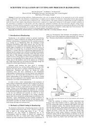
the other h<strong>and</strong> has a boom like a tower <strong>crane</strong>. JIB <strong>crane</strong>s consist <strong>of</strong><br />
these components from bottom to top: At the bottom there are bogie<br />
groups which collect the <strong>crane</strong> wheels [1-4]. Legs are the <strong>element</strong>s<br />
between the bogie groups <strong>and</strong> the main frame. Over the main frame,<br />
there is a cylindrical part which is called pedestal. Engine room is<br />
placed on this pedestal. In the engine room there are balancing<br />
weight <strong>and</strong> the required mechanism for the rotation. On the engine<br />
room there are two drums, one for the boom movements <strong>and</strong> the<br />
other one for lifting the bulk. Also there are two frames on the<br />
engine room, one is called back stay <strong>and</strong> the other one is called A<br />
frame. These frames are connected <strong>with</strong> I-beam pr<strong>of</strong>iles which are<br />
called arm. And the last part <strong>of</strong> JIB <strong>crane</strong> is called boom. Boom has<br />
joints at the bottom <strong>and</strong> also it is connected to the frames <strong>with</strong> steel<br />
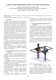
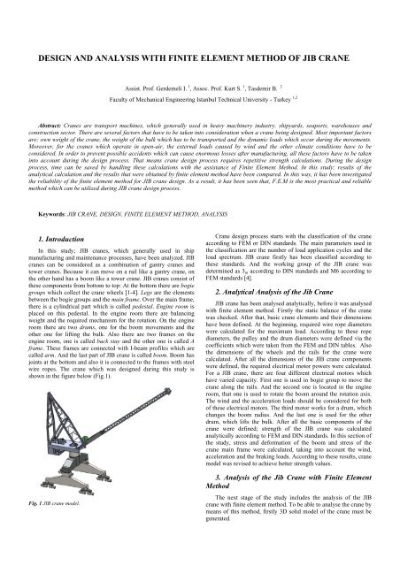
wire ropes. The <strong>crane</strong> which was <strong>design</strong>ed during this study is<br />
shown in the figure below (Fig.1).<br />
Fig. 1 JIB <strong>crane</strong> model.<br />
Crane <strong>design</strong> process starts <strong>with</strong> the classification <strong>of</strong> the <strong>crane</strong><br />
according to FEM or DIN st<strong>and</strong>ards. The main parameters used in<br />
the classification are the number <strong>of</strong> load application cycles <strong>and</strong> the<br />
load spectrum. JIB <strong>crane</strong> firstly has been classified according to<br />
these st<strong>and</strong>ards. And the working group <strong>of</strong> the JIB <strong>crane</strong> was<br />
determined as 3 m according to DIN st<strong>and</strong>ards <strong>and</strong> M6 according to<br />
FEM st<strong>and</strong>ards [4].<br />
2. Analytical Analysis <strong>of</strong> the Jib Crane<br />
JIB <strong>crane</strong> has been analysed analytically, before it was analysed<br />
<strong>with</strong> <strong>finite</strong> <strong>element</strong> <strong>method</strong>. Firstly the static balance <strong>of</strong> the <strong>crane</strong><br />
was checked. After that, basic <strong>crane</strong> <strong>element</strong>s <strong>and</strong> their dimensions<br />
have been defined. At the beginning, required wire rope diameters<br />
were calculated for the maximum load. According to these rope<br />
diameters, the pulley <strong>and</strong> the drum diameters were defined via the<br />
coefficients which were taken from the FEM <strong>and</strong> DIN tables. Also<br />
the dimensions <strong>of</strong> the wheels <strong>and</strong> the rails for the <strong>crane</strong> were<br />
calculated. After all the dimensions <strong>of</strong> the JIB <strong>crane</strong> components<br />
were defined, the required electrical motor powers were calculated.<br />
For a JIB <strong>crane</strong>, there are four different electrical motors which<br />
have varied capacity. First one is used in bogie group to move the<br />
<strong>crane</strong> along the rails. And the second one is located in the engine<br />
room, that one is used to rotate the boom around the rotation axis.<br />
The wind <strong>and</strong> the acceleration loads should be considered for both<br />
<strong>of</strong> these electrical motors. The third motor works for a drum, which<br />
changes the boom radius. And the last one is used for the other<br />
drum, which lifts the bulk. After all the basic components <strong>of</strong> the<br />
<strong>crane</strong> were defined; strength <strong>of</strong> the JIB <strong>crane</strong> was calculated<br />
analytically according to FEM <strong>and</strong> DIN st<strong>and</strong>ards. In this section <strong>of</strong><br />
the study, stress <strong>and</strong> deformation <strong>of</strong> the boom <strong>and</strong> stress <strong>of</strong> the<br />
<strong>crane</strong> main frame were calculated, taking into account the wind,<br />
acceleration <strong>and</strong> the braking loads. According to these results, <strong>crane</strong><br />
model was revised to achieve better strength values.<br />
3. Analysis <strong>of</strong> the Jib Crane <strong>with</strong> Finite Element<br />
Method<br />
The next stage <strong>of</strong> the study includes the <strong>analysis</strong> <strong>of</strong> the JIB<br />
<strong>crane</strong> <strong>with</strong> <strong>finite</strong> <strong>element</strong> <strong>method</strong>. To be able to analyse the <strong>crane</strong> by<br />
means <strong>of</strong> this <strong>method</strong>, firstly 3D solid model <strong>of</strong> the <strong>crane</strong> must be<br />
generated.
3.1 Modelling Of the Crane<br />
Boom, basically consist <strong>of</strong> two components. The bottom side <strong>of</strong><br />
the boom is a box girder <strong>and</strong> the rest <strong>of</strong> it is lattice or truss girder.<br />
The box girder is made <strong>of</strong> sheet metal which has 9 mm thickness.<br />
And the lattice girder consists <strong>of</strong> pipe pr<strong>of</strong>ile beams. The lattice<br />
girder has four main beams, <strong>and</strong> there are support beams between<br />
them which have smaller diameters. The main pipes have 154, 2<br />
mm diameter <strong>and</strong> 10 mm thickness, while support beams have 73<br />
mm diameter, 10 mm thickness <strong>and</strong> 51 mm diameter, 8 mm<br />
thickness. These support <strong>element</strong>s doesn’t carry loads, they are used<br />
to hold the main beams together <strong>and</strong> make the girder more rigid. All<br />
the boom <strong>element</strong>s are made <strong>of</strong> St 52 structural steel.<br />
The main frame or the carrier body <strong>of</strong> the <strong>crane</strong> is a box girder<br />
like the bottom side <strong>of</strong> the boom. But the sheet metals used in the<br />
main frame are much thicker than the ones used in boom’s box<br />
girder. The thickness <strong>of</strong> the sheet metals, used for the main frame’s<br />
box girders, change between 20 mm <strong>and</strong> 24 mm. And as material,<br />
St 37 structural steel was chosen for the main frame <strong>of</strong> the <strong>crane</strong>.<br />
In this study SolidWorks 3D <strong>design</strong> s<strong>of</strong>tware has been used for<br />
modelling the JIB <strong>crane</strong>. All the <strong>crane</strong> components were modelled<br />
one by one, <strong>and</strong> then they were combined in the assembly module<br />
<strong>of</strong> the s<strong>of</strong>tware.<br />
3.2 Analysis <strong>of</strong> the Crane Using ANSYS FEA<br />
S<strong>of</strong>tware<br />
The models, which were generated via SolidWorks CAD<br />
s<strong>of</strong>tware, were transferred to ANSYS <strong>finite</strong> <strong>element</strong> <strong>analysis</strong><br />
s<strong>of</strong>tware <strong>and</strong> they were prepared for the <strong>analysis</strong>. For defining the<br />
problem, firstly the models were meshed in ANSYS s<strong>of</strong>tware.<br />
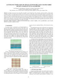
Boom model consists <strong>of</strong> 486.661 <strong>element</strong>s <strong>and</strong> 353.298 nodes.<br />
Components <strong>of</strong> the boom were modelled as surface bodies or shell<br />
<strong>element</strong>s to reduce the <strong>element</strong> <strong>and</strong> node number <strong>of</strong> the model.<br />
Fig. 2 Mesh detail <strong>of</strong> the boom.<br />
After the meshing process, the load combinations <strong>and</strong> the<br />
boundary conditions were defined for the model. Firstly, two<br />
springs were defined for representing the wire ropes. One <strong>of</strong> the<br />
springs, which represent the wire rope that hoists the boom, was<br />
defined <strong>with</strong> a high spring constant for limiting the displacement <strong>of</strong><br />
the boom. And the second spring was defined to represent the wire<br />
rope which lifts the bulk. This second spring was defined <strong>with</strong> a<br />
preload which equals to % 25 <strong>of</strong> the maximum load that desired to<br />
be lifted.<br />
Except the wire ropes, joints <strong>of</strong> the boom have to be defined as<br />
a boundary condition during the pre-process. One degree <strong>of</strong><br />
freedom was defined for these joints which take place at the bottom<br />
section <strong>of</strong> the boom. For these joints, all the movements along X, Y,<br />
Z axis <strong>and</strong> the rotations about Z <strong>and</strong> Y axis were constrained but,<br />
only the rotation about X axis was allowed. After this preparation<br />
process, only st<strong>and</strong>ard earth gravity was defined as an external load<br />
to analyse the stress <strong>and</strong> displacement which were caused by own<br />
weight <strong>of</strong> the boom. According to this first <strong>analysis</strong> it has been seen<br />
that, maximum stress (65-70 MPa) <strong>and</strong> displacement (105, 33 mm)<br />
caused by own weight, occur at the middle section <strong>of</strong> the boom.<br />
Fig. 3 Springs for representing the wire ropes.<br />
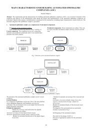
Furthermore, a secondary scenario was applied to the boom<br />
model, for analysing the behaviour <strong>of</strong> the boom under maximum<br />
load combination. For this purpose, the bulk desired to be lift (40<br />
tons), st<strong>and</strong>ard earth gravity, wind loads <strong>and</strong> the loads caused by<br />
acceleration were defined as external loads to the model. Figure 4<br />
illustrates the loads applied to the model in this stage <strong>of</strong> the study.<br />
Fig. 4 JIB <strong>crane</strong> model.<br />
The s<strong>of</strong>tware was runned <strong>with</strong> these boundary conditions <strong>and</strong><br />
the load combinations mentioned above. According to this <strong>analysis</strong>,<br />
stress occurred at the middle section <strong>of</strong> the boom changes between<br />
175 MPa <strong>and</strong> 190 MPa; <strong>and</strong> the stress occurred at the bottom<br />
section <strong>of</strong> the boom changes between 90 MPa <strong>and</strong> 120 MPa. The<br />
stress distribution <strong>of</strong> the boom is shown in Figure 5.<br />
Fig. 5 Result <strong>of</strong> the stress <strong>analysis</strong> under maximum external load.
After the stress <strong>and</strong> displacement <strong>analysis</strong> <strong>of</strong> the boom; the<br />
main frame <strong>of</strong> the <strong>crane</strong> was analysed using ANSYS s<strong>of</strong>tware as<br />
well. Analysis <strong>of</strong> the main frame started <strong>with</strong> meshing process <strong>of</strong><br />
the model. Main frame consists <strong>of</strong> sheet metals <strong>and</strong> has a simple<br />
geometry compared to the boom. As a result it can be meshed much<br />
easier <strong>and</strong> quicker according to the boom. The model <strong>of</strong> main frame<br />
<strong>of</strong> the <strong>crane</strong> consists <strong>of</strong> 84.997 <strong>element</strong>s <strong>and</strong> 169.675 nodes. Figure<br />
6 illustrates the mesh detail <strong>of</strong> the main frame.<br />
Fig. 6 Mesh detail <strong>of</strong> the main frame.<br />
Afterwards the meshing process, the boundary conditions <strong>and</strong><br />
external loads were defined for the main frame <strong>of</strong> the <strong>crane</strong>. Firstly<br />
the model was fixed from the joints where the bogie groups were<br />
connected to. And then, weight <strong>of</strong> the engine room <strong>and</strong> the<br />
components which were located on the engine room were applied<br />
on the model. Also the wind load <strong>and</strong> the loads which were caused<br />
by the acceleration were defined for the model. On the other h<strong>and</strong>,<br />
st<strong>and</strong>ard earth gravity was defined for taking into account the effect<br />
<strong>of</strong> the own weight <strong>of</strong> the main frame. And finally the bending<br />
moment, which was caused by the weight <strong>of</strong> the boom <strong>and</strong> bulk <strong>and</strong><br />
the lateral loads were applied on the model. All the boundary<br />
conditions <strong>and</strong> the loads defined for the main frame are shown in<br />
Figure 7.<br />
Fig. 7 The external loads applied to the main frame.<br />
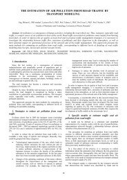
With these boundary conditions <strong>and</strong> the load combinations,<br />
program was runned for the stress <strong>analysis</strong> <strong>of</strong> the main frame.<br />
According to this <strong>analysis</strong>, maximum stress occurs at the triangular<br />
support plates <strong>of</strong> the legs. The stress value detected at this point<br />
equals to 145 MPa which is under the allowable stress 180 MPa for<br />
St 37 structural steel. And the stress value at the bottom section <strong>of</strong><br />
the cylindrical pedestal, changes between 95 MPa <strong>and</strong> 105 MPa.<br />
The stress distribution <strong>of</strong> the main frame is illustrated in Figure 8.<br />
Fig. 8 The stress distribution <strong>of</strong> the main frame.<br />
4. Conculision<br />
At the end <strong>of</strong> the study, results <strong>of</strong> the analytical calculation <strong>and</strong><br />
the results that were obtained by <strong>finite</strong> <strong>element</strong> <strong>method</strong> have been<br />
compared. According to these comparison results, it has been seen<br />
that, the error margins were between the acceptable boundaries.<br />
This comparison is given in the table below (Table 1).<br />
Table 1. Comparison <strong>of</strong> the result.<br />
Section / Loading<br />
Type<br />
Boom Middle Sec.<br />
(Self Weight<br />
+Stress)<br />
Analytical<br />
Calculation<br />
Finite Element<br />
Method<br />
Difference<br />
67,7 MPa 65÷70 MPa % 0,3<br />
Boom Middle Sec.<br />
(Self Weight +<br />
Displacement)<br />
106,39 mm 105,33 mm % 1<br />
Boom Middle<br />
Sec.(Hz) 178,2 MPa 175÷190 MPa % 2,4<br />
Boom<br />
Sec.(Hz)<br />
Middle<br />
101,3 MPa 90÷120 MPa % 3,6<br />
Cylindrical<br />
Pedestal (Hz)<br />
111,6 MPa 95÷105 MPa % 10,3<br />
Stress <strong>and</strong> the deformation results <strong>of</strong> the boom according to<br />
<strong>finite</strong> <strong>element</strong> <strong>method</strong> were fairly similar to analytical calculations.<br />
But it has been seen that, there was % 10 difference between the<br />
two <strong>method</strong>’s stress values for the cylindrical pedestal. This<br />
relatively big error rate comes from the assumption which made<br />
during the analytical calculation. Because there are support plates<br />
inside the pedestal <strong>and</strong> they have been ignored during the analytical<br />
calculation.<br />
On the other h<strong>and</strong>, some spots have been detected in the stress<br />
<strong>analysis</strong> <strong>with</strong> <strong>finite</strong> <strong>element</strong> <strong>method</strong> <strong>of</strong> the boom, which include<br />
high stresses that could not be able to occur in the real system. That<br />
kind <strong>of</strong> spots takes place in the connection areas <strong>of</strong> the beams. This<br />
situation illustrates that, <strong>finite</strong> <strong>element</strong> <strong>method</strong> could be inadequate<br />
over some cases <strong>and</strong> the results should be checked carefully. In this<br />
study, these spots were ignored <strong>and</strong> the stresses which occur several<br />
<strong>element</strong>s away from these spots were taken into consideration. As a<br />
result, it has been seen that if it is applied appropriately <strong>and</strong> the<br />
results could be analysed in the right way, <strong>finite</strong> <strong>element</strong> <strong>method</strong><br />
gave proper results for stress <strong>and</strong> deformation <strong>analysis</strong>.<br />
During the <strong>design</strong> process <strong>of</strong> <strong>crane</strong>s or the similar structures, it<br />
is not enough only system’s being safe in terms <strong>of</strong> strength. The<br />
<strong>design</strong> must fulfil the minimum safety conditions <strong>and</strong> should be<br />
light <strong>and</strong> cheap as well. Therefore, to be able to reach the optimum<br />
<strong>design</strong>, system should be modified <strong>and</strong> revised numerous times.
During all these modifications, calculating the system <strong>with</strong><br />
analytical <strong>method</strong> causes <strong>design</strong> process to take long. In <strong>crane</strong><br />
<strong>design</strong> process <strong>and</strong> the similar studies which require repetitive<br />
calculations, <strong>design</strong>ers can save time by using <strong>finite</strong> <strong>element</strong><br />
<strong>method</strong> on condition that checking the reliability <strong>of</strong> the <strong>method</strong> for<br />
the model. Constructor can change the model in computer<br />
environment <strong>and</strong> get the results <strong>of</strong> the new <strong>design</strong> via <strong>finite</strong> <strong>element</strong><br />
<strong>method</strong> <strong>with</strong>out wasting time. And this is the most practical <strong>and</strong><br />
reliable way to reach the optimum <strong>design</strong> in terms <strong>of</strong> strength,<br />
weight <strong>and</strong> cost.<br />
References<br />
[1] H.Oztepe, (1999) Material H<strong>and</strong>ling, Istanbul Technical<br />
University Ofset Center, Istanbul.<br />
[2] Imrak C.E, Gerdemeli I. (2011) Course Notes <strong>of</strong> Material<br />
H<strong>and</strong>ling, Istanbul Technical University Offset Center, Istanbul.<br />
[3] Gerdemeli I. (2012) Course Notes <strong>of</strong> Material H<strong>and</strong>ling,<br />
Istanbul Technical University Offset Center, Istanbul.<br />
[4] Imrak C.E, Gerdemeli I. (2008) “Strength Equations <strong>and</strong> Finite<br />
Element Modeling <strong>of</strong> JIB Crane Construction”, 5th European<br />
Congress on Computational Methods in Applied Sciences &<br />
Engineering, 30 June – 5 July 2008, Venice, Italy.<br />
[5] Zeid, I . (1991) CAD/CAM Theory <strong>and</strong> Practice, McGraw-Hill,<br />
Delhi.<br />
[6] Gerdemeli I.,Imrak C.E, (2008) “Modeling <strong>of</strong> JIB Crane<br />
Construction Analysis <strong>with</strong> Finite Element Method”, The 13th<br />
International Conference on Problems <strong>of</strong> Material Engineering,<br />
Mechanics & Design, 26-29 August 2008, Rajecke Teplice,<br />
Slovakia