CEILING CONCEALED FAN COIL UNIT
CEILING CONCEALED FAN COIL UNIT
CEILING CONCEALED FAN COIL UNIT

Create successful ePaper yourself
Turn your PDF publications into a flip-book with our unique Google optimized e-Paper software.
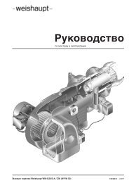
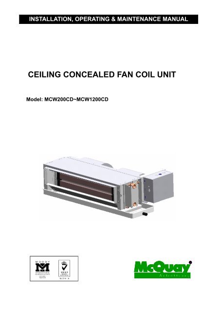
INSTALLATION, OPERATING & MAINTENANCE MANUAL<br />
<strong>CEILING</strong> <strong>CONCEALED</strong> <strong>FAN</strong> <strong>COIL</strong> <strong>UNIT</strong><br />
Model: MCW200CD~MCW1200CD
1<br />
MCW0710-E3<br />
Part No.: M08019012253<br />
This manual provides the procedures of installation to ensure a safe and good<br />
standard of operation for the fan coil unit.<br />
Before using your fan coil unit please read this instruction manual carefully and keep it<br />
for future reference.<br />
CONTENTS<br />
General Information page 2<br />
Features page 3<br />
Outlines and dimensions page 5<br />
Installation page 6<br />
Maintenance page 12<br />
SAFETY PRECAUTIONS<br />
Before installing the fan coil unit, please read the following safety precautions carefully.<br />
Warning<br />
Installation and maintenance should be performed by qualified persons who are familiar with local code and<br />
regulation, and experienced with this type of appliance.<br />
All field wiring must be installed in accordance with the national wiring regulation.<br />
Ensure that the rated voltage of the unit corresponds to that of the nameplate before commencing wiring<br />
work according to the wiring diagram.<br />
Means for disconnection from the supply having a contact separation of at least 3 mm in all poles shall be<br />
incorporated in the fixed wiring according to wiring rules.<br />
The unit must be GROUNDED to prevent possible hazard due to insulation failure.<br />
Confirm that the unit has been switched OFF before installing or servicing the unit.<br />
“McQuay” is a registered trademark of McQuay International. All rights reserved throughout the world.<br />
© 2007 McQuay International<br />
“Bulletin illustrations cover the general appearance of McQuay International products at the time of publication<br />
and we reserve the right to make change in design and construction any time without notice”
GENERAL INFORMATION<br />
This manual has been prepared as guidance for installing and maintaining the McQuay fan coil unit. McQuay<br />
has produced a quality product that will effectively meet your application. However, proper installation and<br />
maintenance procedures must be followed to realize the full capability and life of the unit.<br />
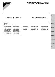
Parts Description<br />
High Efficiency Coil Top Panel<br />
Drain Guide<br />
2<br />
Motor<br />
Centrifugal Fan<br />
Water Connection<br />
Terminal Box<br />
Electric Heater<br />
Condensate Drain Pan
Extra Low Noise Design<br />
FEATURES<br />
Enlarged fan wheels design allows lower fan RPM selection for the same ext. static pressure and airflow<br />
requirement. Thereby, noise level is significantly reduced.<br />
Flexibility<br />
Water connection side can be changed easily in the field by changing positions of the fan-motor assembly<br />
or the supply air flange assembly. Fan -motor assembly is not cased allowing back return or bottom return<br />
installations.<br />
High Efficiency Heat Exchanger<br />
A boundary layer film of air adhering to the fin surface will insulate the fin surface and severely reduces the<br />
heat exchange efficiency. McQuay slit fin design eliminates this boundary layer of air and creates continuous<br />
turbulence for best heat exchange efficiency.<br />
Compact Design<br />
This series of fan coil units are designed to suit most ceiling concealed installations. Unit height is only 251<br />
mm across the entire model range. The feature also maximizes provisions for drain fall requirements.<br />
Auxiliary Electric Heater<br />
The heating source of MCQUAY fan coil unit MCW200CD-1200CD is PTC (Positive Temperature Coefficient)<br />
heater.<br />
1.Safety<br />
A fuse(153 15A) is connected in each PTC main wiring circuit. A thermostat(50 10A) is connected in the<br />
control wiring circuit. If the fan of the unit is not running, the thermostat or fuse will cut off the power of the<br />
unit .In addition, the surface of the PTC heater is without electric power. So the fan coil unit is safe enough.<br />
2.Save energy<br />
Quick heating spread, strong heating capacity, steady performance and save energy are characters of PTC<br />
heater.<br />
3.Easy to install and maintain<br />
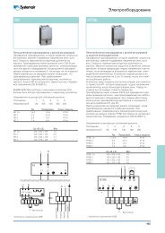
Need not remove the air duct when maintain the electric components of the units. Please refer to Figure1 for<br />
installation and maintenance.<br />
3
Caution<br />
1. The temperature of the surface of PTC heater may be over 200°C if the power of unit is on but the fan of the<br />
unit is not running. Don’t touch the unit at this time!<br />
2. The starting current of the unit is more than its working current. It should be considered both the working<br />
current and starting current while choosing the fuse.<br />
3. When the MCW200CD~MCW1200CD fan coil unit with PTC heater is running, ENSURE there is no<br />
obstructions to air flow into or out of the unit.<br />
Figure 1<br />
4
5<br />
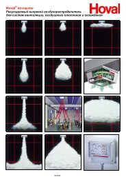
OUTLINES AND DIMENS<br />
Figure 2 Dimension in: mm
INSTALLATION<br />
RECEIVING<br />
All units leaving the McQuay plant have been inspected to ensure the shipment of quality products. All<br />
reasonable means are utilized to properly packing the fan coil unit.<br />
Carefully inspect all shipments immediately upon delivery. When damage is visible, note this fact on the<br />
carrier’s freight bill and request that the carrier send a representative to inspect the damage. This may be<br />
done by telephone or in person, but should always be confirmed in writing.<br />
The shipment should be unpacked in the presence of the agent so that the extent of the damage or loss<br />
can be determined. The carrier’s agent will make a inspection report and a copy will be given to the<br />
consignee for forwarding to the carrier with a formal claim.<br />
CAUTION<br />
Before installation and running the unit, please check the followings:<br />
1. There must be enough space for the unit installation and maintenance. Please refer to Figure 1 for the<br />
unit's outlines and dimensions and Figure 2 for the minimum distance between the unit and the obstacle.<br />
2. Please ensure enough space for piping connection and electrical wiring.<br />
3. Means for disconnection from the supply having a contact separation of at least 3 mm in all poles shall be<br />
incorporated in the fixed wiring according to wiring rules.<br />
4. Check whether the hanging rods can support weight of the unit (see table of specification in page 4).<br />
5. The unit must be installed horizontally to ensure proper operation and condensate draining.<br />
6. The ext. static pressure of the ducting must be within the design static pressure range.<br />
7. The installation agent must supply service valves and insulation for water piping in accordance with the<br />
local code and regulation.<br />
8. Confirm that the unit has been switched OFF before installing or servicing the unit.<br />
Unit Installation<br />
The unit is designed to be installed concealed ceiling and the like. Installation and maintenance<br />
should be performed by qualified persons who are familiar with local code and regulation, and<br />
experienced with this type of appliance.<br />
There are holes on the top of the unit for hanging concealed ceiling. Please refer to Figure 1Figure 2 <br />
Figure 3 and Figure 4.<br />
CAUTION:<br />
Make sure the top level of the unit horizontal while installation. The drain pan is designed with a little<br />
gradient to facilitate drain.<br />
A200mm B400mm C400mm<br />
Figure 3<br />
6
Figure 4<br />
Figure 5<br />
Detail A<br />
Air duct connection<br />
Air duct which is made of galvanized steel can be connected to the flange of the unit. Refer to Figure 1 for<br />
the unit dimensions. Insert the duct into the flange and fix with screws. If dimensions of the duct and flange<br />
are different, connect with a connector between them.<br />
Air duct connection must be installed in accordance with the national code for fire protection and<br />
construction of ventilation and air conditioning works.<br />
7
Pipe connection<br />
Chilled water pipe connection<br />
Connect size Rc3/4 chilled water pipes to the unit. Water inlet is on the bottom and water outlet is on top.<br />
Drain pipe connection<br />
Drain pipe can be either PVC or steel. Connect R3/4 connector to drain pipe of the unit. The connection must<br />
be concealed with rubberized fabric to avoid water leak. The suggested fall of the drain pipe is at least 1:50.<br />
Refer to Figure 6 for typical engineering piping installation.<br />
Electrical wiring<br />
Electrical wiring connection must be done according to the wiring diagram on the unit.<br />
The unit must be GROUNDED to the earth system of the building.<br />
All field wiring must be installed in accordance with the national wiring regulation and Fire Department<br />
regulation.<br />
Electric Heating Power (kW)<br />
Figure 5<br />
Figure 6<br />
Unit Size Power Supply kW kW kW kW kW kW kW kW kW kW kW kW kW<br />
MCW200CD 220-240V~/50Hz 1.0 1.5 2.0 2.5 - - - - - - - - -<br />
MCW300CD 220-240V~/50Hz 1.0 1.5 2.0 2.5 3.0 3.5 - - - - - -<br />
MCW400CD 220-240V~/50Hz 1.0 1.5 2.0 2.5 3.0 3.5 4.0 4.5 - - - - -<br />
MCW600CD 380-415V/3N~/50Hz - - 2.0 2.5 3.0 3.5 4.0 4.5 - - - - -<br />
MCW800CD 380-415V/3N~/50Hz - - 2.0 2.5 3.0 3.5 4.0 4.5 5.0 5.5 - - -<br />
MCW1000CD 380-415V/3N~/50Hz - - 2.0 2.5 3.0 3.5 4.0 4.5 5.0 5.5 - - -<br />
MCW1200CD 380-415V/3N~/50Hz - - - - 3.0 3.5 4.0 4.5 5.0 5.5 6.0 7.0 8.0<br />
8
WARNING:<br />
Switch shall be connected to the supply terminals and shall have a contact separation of at least 3<br />
mm in each pole.<br />
Confirm that the unit has been switched OFF before installing or servicing the unit.<br />
OPTIONAL PARTS<br />
Electric valve package kits<br />
The electric valve package kits are furnished completely soldered and leak tested at the factory. Four(4)<br />
solder connections are required to complete the installation of the valve package into the system (two at the<br />
coil supply and return connections and two at the supply and return run outs).<br />
Installation<br />
1. Clean all connections before assembly with fine sandpaper. A good grade solder flux will help ensure a<br />
proper bond. A general purpose 50/50 solder is recommended. Do not silver solder or braze the<br />
valves or copper fittings in this kit. A chill block, or equivalent, must be used to prevent leaks in the<br />
factory connection or overheating the valve.<br />
2. Position the valve package on the unit by moving the kit piping slightly. Do not try to move the coil<br />
connections.<br />
3. The 24indentation in the back of the secondary drain pan on the units is provided for the supply<br />
and return run outs if they are brought up from below the pan. We recommend removing or covering the<br />
secondary drain pan on these units before soldering the coil connections as hot solder or the torch flame<br />
could damage the pan. Be careful not to burn wire insulation during soldering.<br />
4. Caution: The electric valve and gate valves are to be in the open position, ball valves in the<br />
closed position while soldering. Do not move the valve handles until the tubing has cooled for<br />
three (3) minutes.<br />
5. A hydrostatic test on all piping is recommended after all connections are complete.<br />
6. All piping not over the secondary drain pan must be well insulated to prevent sweating. There is an 0.840<br />
O.D. condensate drain connection on the unit drain pan suitable for a 1/2plastic pipe fitting (by others).<br />
7. Field wiring must be in accordance with local codes and/or the National Electrical Code. Wiring should be<br />
routed in such a manner to prevent the possibility of condensate dripping from the valve package piping<br />
onto the electrical conduit.<br />
Caution<br />
To prevent electrical shock, disconnect electric power to<br />
system at main fuse or circuit breaker box until installation<br />
Valve Actuator installation<br />
Latch the manual operating lever in the engaged position (N.C. only). Depress the release button (See<br />
Figure 7). Align the body with the actuator to ensure the stem is inserted into the large mating hole on the<br />
bottom side of the actuator. Engage the actuator on the body and release the button. Actuator AG2 is used<br />
or normally open operation. Actuator AG1 is used for normally closed operation.<br />
Mounting<br />
The PopTop TM valve can be mounted vertically or horizontally. If mounted horizontally, the valve should be<br />
mounted within 90of upright position (See Figure 8). If mounted vertically, care should be taken to ensure<br />
moisture does not drip onto motor. The valve actuator should not be mounted upside down.<br />
9
Release<br />
Button<br />
Room Thermostats<br />
The RAB10… room thermostat is used in heating or cooling systems to maintain the selected room<br />
temperature.<br />
Functions<br />
Heating If the room temperature falls below the selected setpoint, the heating contact will close.<br />
Cooling If the room temperature exceeds the selected setpoint, the cooling contact will close.<br />
Fan speed There are two possibilities to control the fan speed:<br />
a) Manually by means of the three-speed fan switch on the thermostat for continuous<br />
operation.<br />
b) Automatically by switching to the selected fan speed via the thermostat for controlled<br />
operation. In that case - prior to commissioning - the thermostat function must be changed.<br />
There are two choices available:<br />
Ventilation<br />
Figure 7<br />
Auto<br />
Manual<br />
Operating<br />
Lever<br />
Mating Hole<br />
Stem<br />
Selected fan speed as continuous operation<br />
Fan is switched at the same time as the valve<br />
Upside Down Vertical<br />
Figure 8<br />
When the ventilation function is selected (RAB10.1), the heating and cooling contacts are always open and<br />
the fan operates at the selected speed.<br />
Changeover<br />
Heating or cooling is selected with a switch located on the front of the thermostat.<br />
Adjustments<br />
The required temperature can be selected by a setpoint adjuster on the front of the thermostat.<br />
The setpoint setting range can be mechanically limited by means of tappets under the unit over.<br />
Mounting, installation and commissioning<br />
The thermostat should be located where the air temperature can be sensed as accurately as possible,<br />
without getting adversely affected by direct solar radiation or other heat or refrigeration sources.<br />
Mounting height is about 1.5 m above the floor.<br />
The unit can be fitted to most commercially available recessed conduit boxes or directly on the wall.<br />
Only authorized personnel may open the unit to perform service .<br />
The unit must be isolated from the main supply before opening.<br />
When installing the unit, fix the base plate first, then hook on the thermostat body and make the electrical<br />
connections. Then fit the cover and secure it (also refer to separate mounting instructions).<br />
10
The thermostat must be mounted on a flat wall.<br />
The local electrical regulations must be complied with.<br />
If there are thermostatic radiator valves in the reference room, set them to their fully open position.<br />
Maintenance<br />
The room thermostat is maintenance-free.<br />
Technical data<br />
Power supply Operating voltage AC 250 V<br />
Frequency 50 or 60 Hz<br />
Operational data Switching differential SD 1 K<br />
Set point setting range 8~30<br />
Amperage at AC 250 V 0.2~6 (2) A<br />
Environmental conditions Operation to IEC 721-3-3<br />
Climatic conditions class 3K5<br />
Temperature 0~+50<br />
Humidity 95% r.h.<br />
Pollution degree normal, to EN 60730<br />
Norms and standards CE conformity to<br />
Low voltage directive 73/23/EEC and 93/68/EEC<br />
Product standard EN 60730<br />
Safety standard EN 60730<br />
Degree of protection IP30 to EN 60529<br />
Screw terminals for 21.5 mm 2 or 12.5 mm 2 , min. (0.5 mm 2 )<br />
Weight 0.14 kg<br />
Color white, NCS S 0502-G (RAL 9003)<br />
Connection diagram<br />
Figure 9<br />
The electric valve package kits and room thermostat are optional parts. If they are required by customers, the<br />
electric valve<br />
11<br />
L Operating voltage AC 250 V<br />
M 3-speed fan<br />
N Neutral<br />
Q1 Control output<br />
“Fan speed ”, AC 250 V<br />
Q2 Control output<br />
“Fan speed ”, AC 250 V<br />
Q3 Control output<br />
“Fan speed ”, AC 250 V<br />
Y Control output<br />
“Valve actuator”, AC 250 V<br />
D Thermal valve or zone valve
package kits can be installed in factory (refer to Figure 10) and the room thermostat will be with the unit as<br />
accessory<br />
Figure 10<br />
MAINTENANCE<br />
General<br />
Installation and maintenance should be performed by qualified persons who are familiar with local code and<br />
regulation, and experienced with this type of appliance.<br />
Confirm that the unit has been switched OFF before installing or servicing the unit.<br />
A good general maintenance plan will avoid loses and unexpected shutting down of the equipment.<br />
Dirty filters reduce air flow as well as unit performance. Thus changing or cleaning the filters is very<br />
important. Check the cleanliness of filter and replace or clean as required monthly.<br />
Coils shall be cleaned from dust, dirt or lint with compressed air, water. They can be brushed with a soft<br />
brush and vacuum cleaner.<br />
Water coil not used during winter season shall be drained, or anti-freezing solution shall be added to the<br />
water circuit to avoid freezing.<br />
Month intervals<br />
1 Inspect and clean condensate drain pan to avoiding clogging of drainage by dirt, dust, etc. Inspect<br />
drainage piping to ensure the proper condensate flow.<br />
2 Check and clean the coil. Clean the coils with low pressure water jet or low pressure air.<br />
3 Clean and tighten all the wiring connections.<br />
4 Drain out the system water and check for build up of mineral deposits.<br />
12<br />
2-way valve<br />
Water outlet<br />
Brass connector<br />
Water inlet
While utmost care is taken in ensuring that all details in the publication are correct at the time of<br />
going to press, we are constantly striving for improvement and therefore reserve the right to alter<br />
model specifications and equipment without notice. Details of specifications and equipment are also<br />
subject to change to suit local conditions and requirements and not all models are available in every<br />
market.