Concept Study for a 10MWth Chemical Looping Combustor for ...
Concept Study for a 10MWth Chemical Looping Combustor for ...
Concept Study for a 10MWth Chemical Looping Combustor for ...

Create successful ePaper yourself
Turn your PDF publications into a flip-book with our unique Google optimized e-Paper software.
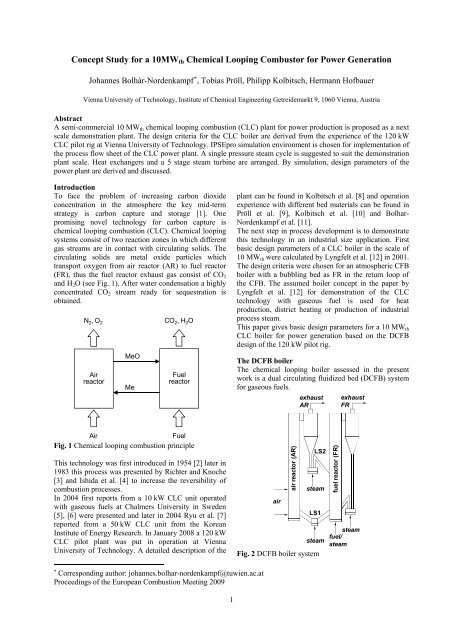
<strong>Concept</strong> <strong>Study</strong> <strong>for</strong> a <strong>10MWth</strong> <strong>Chemical</strong> <strong>Looping</strong> <strong>Combustor</strong> <strong>for</strong> Power Generation<br />
<br />
Johannes Bolhàr-Nordenkampf , Tobias Pröll, Philipp Kolbitsch, Hermann Hofbauer<br />
Vienna University of Technology, Institute of <strong>Chemical</strong> Engineering Getreidemarkt 9, 1060 Vienna, Austria<br />
Abstract<br />
A semi-commercial 10 MWth chemical looping combustion (CLC) plant <strong>for</strong> power production is proposed as a next<br />
scale demonstration plant. The design criteria <strong>for</strong> the CLC boiler are derived from the experience of the 120 kW<br />
CLC pilot rig at Vienna University of Technology. IPSEpro simulation environment is chosen <strong>for</strong> implementation of<br />
the process flow sheet of the CLC power plant. A single pressure steam cycle is suggested to suit the demonstration<br />
plant scale. Heat exchangers and a 5 stage steam turbine are arranged. By simulation, design parameters of the<br />
power plant are derived and discussed.<br />
Introduction<br />
To face the problem of increasing carbon dioxide<br />
concentration in the atmosphere the key mid-term<br />
strategy is carbon capture and storage [1]. One<br />
promising novel technology <strong>for</strong> carbon capture is<br />
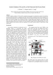
chemical looping combustion (CLC). <strong>Chemical</strong> looping<br />
systems consist of two reaction zones in which different<br />
gas streams are in contact with circulating solids. The<br />
circulating solids are metal oxide particles which<br />
transport oxygen from air reactor (AR) to fuel reactor<br />
(FR), thus the fuel reactor exhaust gas consist of CO2<br />
and H2O (see Fig. 1). After water condensation a highly<br />
concentrated CO2 stream ready <strong>for</strong> sequestration is<br />
obtained.<br />
N 2, O 2<br />
Air<br />
reactor<br />
MeO<br />
Me<br />
CO 2, H 2O<br />
Fuel<br />
reactor<br />
Air<br />
Fuel<br />
Fig. 1 <strong>Chemical</strong> looping combustion principle<br />
This technology was first introduced in 1954 [2] later in<br />
1983 this process was presented by Richter and Knoche<br />
[3] and Ishida et al. [4] to increase the reversibility of<br />
combustion processes.<br />
In 2004 first reports from a 10 kW CLC unit operated<br />
with gaseous fuels at Chalmers University in Sweden<br />
[5], [6] were presented and later in 2004 Ryu et al. [7]<br />
reported from a 50 kW CLC unit from the Korean<br />
Institute of Energy Research. In January 2008 a 120 kW<br />
CLC pilot plant was put in operation at Vienna<br />
University of Technology. A detailed description of the<br />
Corresponding author: johannes.bolhar-nordenkampf@tuwien.ac.at<br />
Proceedings of the European Combustion Meeting 2009<br />
1<br />
plant can be found in Kolbitsch et al. [8] and operation<br />
experience with different bed materials can be found in<br />
Pröll et al. [9], Kolbitsch et al. [10] and Bolhar-<br />
Nordenkampf et al. [11].<br />
The next step in process development is to demonstrate<br />
this technology in an industrial size application. First<br />
basic design parameters of a CLC boiler in the scale of<br />
10 MWth were calculated by Lyngfelt et al. [12] in 2001.<br />
The design criteria were chosen <strong>for</strong> an atmospheric CFB<br />
boiler with a bubbling bed as FR in the return loop of<br />
the CFB. The assumed boiler concept in the paper by<br />
Lyngfelt et al. [12] <strong>for</strong> demonstration of the CLC<br />
technology with gaseous fuel is used <strong>for</strong> heat<br />
production, district heating or production of industrial<br />
process steam.<br />
This paper gives basic design parameters <strong>for</strong> a 10 MWth<br />
CLC boiler <strong>for</strong> power generation based on the DCFB<br />
design of the 120 kW pilot rig.<br />
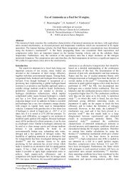
The DCFB boiler<br />
The chemical looping boiler assessed in the present<br />
work is a dual circulating fluidized bed (DCFB) system<br />
<strong>for</strong> gaseous fuels.<br />
air<br />
air reactor (AR)<br />
exhaust<br />
AR<br />
LS2<br />
steam<br />
LS1<br />
fuel reactor (FR)<br />
exhaust<br />
FR<br />
steam fuel/<br />
steam<br />
steam<br />
Fig. 2 DCFB boiler system
The boiler design is based on the Vienna 120 kW pilot<br />
rig which was designed with a direct focus on<br />
scalability to larger size. The nominal power of the<br />
boiler is 10 MW with natural gas as the fuel. Loop seals<br />
between the reactors fluidized with superheated steam<br />
avoid mixing of AR and FR gases. The flow regime in<br />
the AR is fast fluidization and in the FR turbulent<br />
fluidization [8]. Downstream of each reactor, gas and<br />
solids are separated in cyclone separators. The general<br />
setup is shown in Fig. 2.<br />
The basic assumption <strong>for</strong> the boiler parameters is based<br />
on the experience on the 120 kW pilot rig. The<br />
important values are summarized in Table 1.<br />
Table 1<br />
Chosen or assumed parameter values<br />
Item Value Unit<br />
Power (fuel) ~40MJ/kg 10 MW<br />
heat loss (reactor system) 2 %<br />
AR cross section 1.6 m 2<br />
AR pressure drop 7 kPa<br />
FR cross section 0.75 m 2<br />
FR temperature 900 °C<br />
FR pressure drop 14.5 kPa<br />
air/fuel ratio 1.1 -<br />
solid conversion difference 10 %<br />
mean AR oxidation state 50 %<br />
Oxygen carrier characterization<br />
The basic requirements <strong>for</strong> oxygen carriers (OCs) are<br />
mechanical stability, lowest possible costs and high<br />
oxygen transport capacity. Depending on the used fuel<br />
the OC has to fulfill other requirements too. For<br />
hydrocarbon fuels a high catalytic activity is beneficial<br />
(especially <strong>for</strong> methane conversion). Ni-based carriers<br />
have a good catalytic activity and are suitable <strong>for</strong><br />
methane combustion and re<strong>for</strong>ming. Other possible<br />
metals besides Ni are: Cu, Fe, Co, Mn and Cd [13, 14,<br />
15, 16, 17, 18, 19]. Most oxides have to be supported by<br />
other inert materials to gain the necessary mechanical<br />
strength and attrition stability to be operated in a CFB.<br />
Such support materials can be Al2O3, TiO2 or yttriastabilized<br />
zirconium (YSZ) [12].<br />
In the present study, highly active carriers Ni particles<br />
are used. The OC is based on NiO, α-Al2O3 and MgO.<br />
More in<strong>for</strong>mation on the OCs used can be found in the<br />
article by [20]. The particle size of the OC is in the<br />
range of 90 210 µm. The oxygen carrier characteristics<br />
are summarized in Table 2.<br />
Table 2<br />
Oxygen carrier characterization<br />
Item Value Unit<br />
oxygen carrier system Ni/NiO -<br />
support materials Al2O3 + MgO -<br />
NiO content 41.3 wt%<br />
dp 90-210 µm<br />
2<br />
The values of Table 1 and Table 2 together with the<br />
CLC reactor model implemented in the simulation<br />
software IPSEpro give the basis <strong>for</strong> further calculation.<br />
The simulation software IPSEpro<br />
IPSEpro is a stationary, equation orientated simulation<br />
software. It was designed in a modular structure. The<br />
main structure consist of the user interface (process<br />
simulation environment, PSE), the model library and the<br />
equation solver (Kernel). The PSE is the main<br />
component of IPSEpro, because there the process is<br />
modeled and data is entered/read. During the<br />
calculation, data from the PSE (settings, parameters) is<br />
sent to the equation solver (Kernel). The solver calls in<br />
data from a model library that contains all in<strong>for</strong>mation<br />
about the inner structure of the apparatuses used in the<br />
process. The model development kit, a user interface to<br />
change the model library, enables the user to edit the<br />
source code of the standard model as well as to create<br />
new models <strong>for</strong> special tasks. (e.g. introduce new<br />
substances classes, etc.). A more detailed description on<br />
the IPSEpro Simulation Software and on the<br />
implemented CLC model can be found elsewhere [21].<br />
Flow sheet simulation <strong>for</strong> chemical looping processes<br />
with IPSEpro<br />
Due to the relative novelty of the CLC process, most<br />
commercial tools do not yet offer a possibility <strong>for</strong><br />
treatment of solid streams or of gas-solid reactions as<br />
needed <strong>for</strong> CLC. The software IPSEpro offers an open<br />
structure <strong>for</strong> implementation of a new model library<br />
specially designed <strong>for</strong> chemical looping based<br />
processes. Bolhar-Nordenkampf et al. [21] presents the<br />
so-called advanced energy technology library (AET-<br />
Lib), which is an extended version of a comprehensive<br />
model library previously built <strong>for</strong> gasification-based<br />
processes [22]. The properties of 40 solid substances<br />
potentially involved in CLC/CLR processes have been<br />
collected from databases and implemented into the<br />
IPSEpro structure.<br />
The CLC model implemented in the IPSEpro<br />
environment was validated by empirical measurements<br />
of the 120 kW pilot rig. A flow sheet simulation of the<br />
whole pilot plant setup (reactor, gas cooler, post<br />
combustor and filter) was used <strong>for</strong> parameter evaluation<br />
by means of reconciled calculation [21].<br />
In this paper the process model is used <strong>for</strong> predictive<br />
simulation of chemical looping combustion <strong>for</strong> power<br />
production. The basic setup can be seen in the IPSEpro<br />
flow sheet shown in Fig. 3. Such a boiler is suitable <strong>for</strong><br />
semi-commercial demonstration of CLC technology <strong>for</strong><br />
gaseous fuels. At this scale a simple heat recovery setup<br />
is proposed. The steam cycle parameters (live steam<br />
parameters, efficiencies) can be found in Table 3.
Table 3<br />
Steam cycle parameters<br />
Item Value Unit<br />
Steam temperature 520 °C<br />
Steam turbine inlet pressure 60 bar(a)<br />
Condenser pressure 0.1 bar(a)<br />
total steam turbine efficiency 89.4 %<br />
generator efficiency 97.5 %<br />
pump efficiency 70 %<br />
motor drive efficiency 90 %<br />
Cooling water inlet temperature 15 °C<br />
Cooling water outlet temperature 25 °C<br />
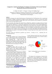
The process flow diagram in Fig. 3 represents the entire<br />
CLC plant without CO2 compression. The input streams<br />
fuel, air and fresh bed material as well as the output<br />
streams AR exhaust, FR exhaust (i.e. CO2 and H2O),<br />
condensed water and used bed material are the system<br />
boundaries of the plant. Air is provided at ambient<br />
pressure and is preheated with heat from the AR exhaust<br />
bed<br />
material<br />
fresh<br />
air<br />
natural gas<br />
turbine<br />
AR<br />
aph<br />
gas whereas the fuel is available at elevated pressure<br />
and ambient temperature, i.e. only a gas compressor <strong>for</strong><br />
air is needed. The fuel is taken from the natural gas grid<br />
and mainly consists of methane. The IPSEpro<br />
simulation covers the CLC boiler, the heat recovery<br />
steam generator and the integrated steam cycle with a<br />
steam turbine <strong>for</strong> power generation. A single pressure<br />
steam cycle in natural circulation with no reheat and<br />
live steam parameters of 520°C at 60bar(a) is designed.<br />
The steam turbine has 5 stages with bled steam<br />
connection <strong>for</strong> feed-water heating and deaeration of the<br />
G<br />
sh<br />
stgen<br />
FR<br />
3<br />
condensed water. The setup of the heat recovery steam<br />
generator includes the AR and FR heat recovery boiler<br />
and a fluidized bed heat exchanger (FB-HE). The<br />
proposed AR heat recovery boiler consists of a steam<br />
generator, an economizer and an air preheater. The<br />
components of the AR exhaust gas are N2 and unreacted<br />
O2, i.e. the risk of corrosion is very low. There<strong>for</strong>e it<br />
seems feasible to recover heat from the AR exhaust<br />
stream down to 60°C.<br />
The heat of the FR exhaust gas is withdrawn by a steam<br />
generator. Some of the heat recovered in a FR exhaust<br />
gas condenser is used to preheat low temperature feed<br />
water. In order to reduce the dew point to 25°C,<br />
however, some cooling water is required. At the<br />
operating parameters chosen (see Table 1), the produced<br />
heat in the reactors is larger than the sensible heat in the<br />
exhaust gas streams. There<strong>for</strong>e a FB-HE has to be<br />
arranged. This FB-HE consists of two parts, a super<br />
heater and a steam generator. The FB-HE is arranged in<br />
the back loop of the AR.<br />
stgen<br />
cond pump<br />
Fig. 3 Basic setup of a chemical looping combustor <strong>for</strong> power production<br />
stgen<br />
pump<br />
drum<br />
eco<br />
fwph<br />
depleted air<br />
CO 2 to<br />
compression<br />
water<br />
Results and Discussion<br />
It is demonstrated that the IPSEpro environment is<br />
suitable <strong>for</strong> flow sheet simulation of CLC processes. A<br />
10 MWth CLC boiler with heat recovery and a single<br />
pressure steam cycle is successfully simulated. The<br />
assumed parameters are conservative and CLC reactor<br />
parameters are based on the experience of the 120 kW<br />
pilot plant [9, 10, 11]. Different basic design parameters<br />
are derived from the flow sheet simulation and<br />
presented. The bed material holdup in the two reactors
is calculated. The turbulent regime in the FR enhances<br />
gas-solid contact and thus allows a reduction of the<br />
solids inventory [23]. This is one of the advantages of a<br />
turbulent FR concept especially relevant at increased<br />
plant capacities. The necessary mass in the FR per MW<br />
thermal input decreases from 510 kg/MW to<br />
110 kg/MW [8].<br />
The AR has a solid inventory of 1140 kg and is in the<br />
same range as in the concept of Lyngfelt et al. [12]. It is<br />
important to notice that the bed mass in the loop seal<br />
and the FB-HE is not considered. The solid circulation<br />
rate Gs of 57.1 kg/m²s corresponds to the solid<br />
conversion difference of 10% and is in the typical range<br />
of CFB risers. According to Smolders and Baeyens [24],<br />
GS can reach values up to 100 kg/m²s in CFB systems.<br />
The energy consumption of all auxiliary units is in the<br />
range of 1% of the thermal input. The overall net<br />
electric efficiency of the 10 MWth CLC power plant is<br />
36.3%. With respect to the semi-commercial scale of the<br />
plant this efficiency value may be acceptable, however,<br />
more work is needed to assess the potential. The main<br />
results of the process flow sheet simulation are<br />
summarized in Table 4.<br />
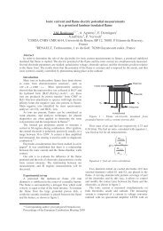
CLC features the principle of a chemical heat pump [3].<br />
The basic principle of a chemical heat pump is to bind<br />
chemical energy at a lower temperature to the bed<br />
material, then transport it to a second reactor where the<br />
chemical energy is released as heat at a higher<br />
temperature level. This sensible heat is partly contained<br />
in the exhaust gas of the reactor and partly in the<br />
returning bed material.<br />
Fig. 4 Energy flows in the 10 MWth CLC boiler<br />
4<br />
Table 4<br />
Parameter values derived from simulation and the basic<br />
assumptions<br />
Item Value Unit<br />
Fuel flow 0.28 Nm³/s<br />
Air flow 2.87 Nm³/s<br />
FR superficial velocity 4.8 m/s<br />
AR superficial velocity 7.3 m/s<br />
FR bed mass 710 kg<br />
AR bed mass 1140 kg<br />
solid circulation rate GS 57.1 kg/(m²s)<br />
solid flow from AR 85.6 kg/s<br />
solid flow to AR 84.8 kg/s<br />
air fan power 61 kW<br />
pump power 49 kW<br />
net electric efficiency 36.3 %<br />
The Sankey diagram in Fig. 4 shows this principle <strong>for</strong><br />
the 10 MWth CLC boiler. The total energy transported<br />
by the gas streams is based on specific sensible enthalpy<br />
and lower heating value. For clear illustration of the<br />
energy transported by the circulating solids, the<br />
following two set points were determined. Firstly, the<br />
energy flow from the FR to AR consists only of<br />
chemical energy, i.e. the sensible heat of the bed<br />
material stream at 900°C is set to 0. Secondly, the<br />
returning bed material to the fuel reactor consists only<br />
of sensible heat released in the exothermic AR. i.e. the<br />
chemical energy in this energy stream is set to 0. This<br />
means, in other words, that the sensible heat entering<br />
the fuel reactor is the difference in sensible heat<br />
between the solids stream entering and leaving the FR.
Accordingly, the chemically bound energy in the solids<br />
stream to the AR is only the difference to the chemically<br />
bound energy present in the returning solids stream.<br />
The main energy input in the FR is the natural gas. For<br />
the conversion of the fuel some additional heat is<br />
needed as the reaction is slightly endothermic (Ni-based<br />
particles). This heat is transported into the FR by<br />
returning bed material from the AR. In the FR the<br />
energy input is bound primarily to the outgoing bed<br />
material as chemical energy. The smaller part is<br />
released with the exhaust gas stream. The bed material<br />
transports the chemical energy to the AR where in<br />
interaction with the preheated air it is trans<strong>for</strong>med to<br />
sensible heat at a higher temperature level (e.g. 980°C).<br />
This heat is than released in the exhaust gas stream and<br />
in the returning bed material stream. The major part is<br />
bound to the bed material. To fulfill the energy balance<br />
of the system, heat has to be withdrawn by a FB-HE out<br />
of the bed material. The loop is closed by the returning<br />
energy flow to the FR.<br />
Conclusions<br />
Based on a continuous development of the CLC<br />
technology from laboratory scale to pilot scale started in<br />
2000, a first basic design <strong>for</strong> a semi-commercial<br />
10 MWth CLC plant <strong>for</strong> power production is proposed.<br />
The design criteria <strong>for</strong> the CLC boiler are based on the<br />
experience from a 120 kW CLC pilot rig operated since<br />
January 2008. The CLC boiler represents the DCFB<br />
concept of the 120 kW pilot rig. The IPSEpro<br />
simulation environment is chosen <strong>for</strong> implementation of<br />
the CLC reactor model which was validated by<br />
empirical measurements. On the basis of successful<br />
implementation of the required unit operations, the<br />
process flow sheet of a whole power plant has been set<br />
up. A single pressure steam cycle with live steam<br />
parameters of 520°C and 60 bar is suggested to suit the<br />
demonstration plant scale. Heat exchangers are arranged<br />
to recover heat from the bed material and exhaust gas<br />
streams. A five-stage steam turbine is designed with<br />
conservative efficiency estimation. The simulation<br />
provides additional design parameters (mass flow,<br />
volume flows, velocities, etc.). The net electric<br />
efficiency of 36.3% is feasible <strong>for</strong> the scale of the plant.<br />
However, more work is needed to assess the potential of<br />
such a concept be<strong>for</strong>e any final conclusion can be made.<br />
Acknowledgements<br />
The model library <strong>for</strong> CLC processes was developed in<br />
the EU financed project CLC GAS POWER (FP6<br />
Contract No. 019800), coordinated by Chalmers<br />
University of Technology. The project was also part of<br />
Phase II of CCP (CO2 Capture Project) through Shell.<br />
References<br />
[1] F. Birol, World Energy Outlook 2006,<br />
International Energy Agency (IEA), 2006.<br />
[2] W. K. Lewis, E. R. Gilliland, Production of pure<br />
carbon dioxide, U.S. Patent Office, Number<br />
2,665,972 (1954).<br />
5<br />
[3] H. J. Richter, K. F. Knoche, Reversibility of<br />
combustion processes., ACS Symposium Series<br />
235 (1983) 71–85.<br />
[4] M. Ishida, D. Zheng, T. Akehata, Evaluation of a<br />
chemical-looping-combustion power-generation<br />
system by graphic exergy analysis, Energy 12 (2)<br />
(1987) 147–154.<br />
[5] A. Lyngfelt, H. Thunman, Construction and 100h<br />
of operational experience of a 10-kW chemical<br />
looping combustor, in: Carbon Dioxide Capture<br />
<strong>for</strong> Storage in Deep Geologic Formations, Elsevier<br />
Science, Amsterdam, 2005, Ch. 31, pp. 625–645.<br />
[6] A. Lyngfelt, B. Kronberger, J. Adanez, J.-X.<br />
Morin, P. Hurst, The GRACE project:<br />
Development of oxygen carrier particles <strong>for</strong><br />
chemical-looping combustion. Design and<br />
operation of a 10 kW chemical-looping<br />
combustor, in: 7th Conference on Greenhouse Gas<br />
Control Technologies, Vancouver, Canada, 2004,<br />
pp. –.<br />
[7] H. Ryu, G. Jin, C. Yi, Demonstration of inherent<br />
CO2 separation and no NOx emission in a 50 kW<br />
chemical-looping combustor: Continuous<br />
reduction and oxidation experiment, in: 7th<br />
Conference on Greenhouse Gas Control<br />
Technologies (GHGT7), Vancouver, Canada,<br />
2004.<br />
[8] P. Kolbitsch, J. Bolhar-Nordenkampf, T. Pröll,<br />
H. Hofbauer, Design of a chemical looping<br />
combustor using a dual circulating fluidized bed<br />
(DCFB) reactor system, <strong>Chemical</strong> Engineering<br />
and Technology 32 (3) (2009) 398–403.<br />
[9] T. Pröll, K. Mayer, J. Bolhar-Nordenkampf,<br />
P. Kolbitsch, T. Mattisson, A. Lyngfelt,<br />
H. Hofbauer, Natural minerals as oxygen carriers<br />
<strong>for</strong> chemical looping combustion in a dual<br />
circulating fluidized bed system, accepted <strong>for</strong><br />
publication in Energy Procedia.<br />
[10] P. Kolbitsch, T. Pröll, J. Bolhar-Nordenkampf,<br />
H. Hofbauer, Operating experience with chemical<br />
looping combustion in a 120 kW dual circulating<br />
fluidized bed (DCFB) unit, accepted <strong>for</strong><br />
publication in Energy Procedia.<br />
[11] J. Bolhar-Nordenkampf, T. Pröll, P. Kolbitsch,<br />
H. Hofbauer, Per<strong>for</strong>mance of a NiO-based oxygen<br />
carrier <strong>for</strong> chemical looping combustion and<br />
re<strong>for</strong>ming in a 120 kW unit, accepted <strong>for</strong><br />
publication in Energy Procedia.<br />
[12] A. Lyngfelt, B. Leckner, T. Mattisson, A fluidizedbed<br />
combustion process with inherent CO2<br />
separation; application of chemical-looping<br />
combustion., <strong>Chemical</strong> Engineering Science<br />
56 (10) (2001) 3101–3113.<br />
[13] A. Abad, J. Adanez, F. Garcia-Labiano, L. F.<br />
de Diego, P. Gayan, J. Celaya, Mapping of the<br />
range of operational conditions <strong>for</strong> Cu-, Fe-, and<br />
Ni-based oxygen carriers in chemical-looping<br />
combustion., <strong>Chemical</strong> Engineering Science<br />
62 (1-2) (2007) 533–549.
[14] F. Garcia-Labiano, J. Adanez, L. F. de Diego,<br />
P. Gayan, A. Abad, Effect of pressure on the<br />
behavior of copper-, iron-, and nickel-based<br />
oxygen carriers <strong>for</strong> chemical-looping combustion.,<br />
Energy & Fuels 20 (1) (2006) 26–33.<br />
[15] M. Johansson, T. Mattisson, A. Lyngfelt, Use of<br />
NiO/NiAl2O4 particles in a 10 kW chemicallooping<br />
combustor., Industrial & Engineering<br />
Chemistry Research 45 (17) (2006) 5911–5919.<br />
[16] T. Mattisson, M. Johansson, A. Lyngfelt, The use<br />
of NiO as an oxygen carrier in chemical-looping<br />
combustion., Fuel 85 (5-6) (2006) 736–747.<br />
[17] S. R. Son, S. D. Kim, <strong>Chemical</strong>-looping<br />
combustion with NiO and Fe2O3 in a<br />
thermobalance and circulating fluidized bed<br />
reactor with double loops, Industrial &<br />
Engineering Chemistry Research 45 (8) (2006)<br />
2689–2696.<br />
[18] A. Abad, T. Mattisson, A. Lyngfelt, M. Johansson,<br />
The use of iron oxide as oxygen carrier in a<br />
chemical-looping reactor., Fuel 86 (7-8) (2007)<br />
1021–1035.<br />
[19] B. M. Corbella, J. M. Palacios, Titania-supported<br />
iron oxide as oxygen carrier <strong>for</strong> chemical-looping<br />
6<br />
combustion of methane., Fuel 86 (1-2) (2007)<br />
113–122.<br />
[20] E. Jerndal, I. Thijs, F. Snijkers, T. Mattisson,<br />
A. Lyngfelt, NiO particles with Ca and Mg based<br />
additives produced by spray-drying as oxygen<br />
carriers <strong>for</strong> chemical-looping combustion,<br />
accepted <strong>for</strong> publication in Energy Procedia.<br />
[21] J. Bolhar-Nordenkampf, T. Pröll, P. Kolbitsch,<br />
H. Hofbauer, Comprehensive modeling tool <strong>for</strong><br />
chemical looping bas processes, <strong>Chemical</strong><br />
Engineering and Technology 32 (3) (2009) 410–<br />
417.<br />
[22] T. Pröll, H. Hofbauer, Development and<br />
application of a simulation tool <strong>for</strong> biomass<br />
gasification based processes, International Journal<br />
of <strong>Chemical</strong> Reactor Engineering 6 (2008) –.<br />
http://www.bepress.com/ijcre/vol6/A89<br />
[23] J. R. Grace, High-velocity fluidized bed reactors,<br />
<strong>Chemical</strong> Engineering Science 45 (8) (1990)<br />
1953–1966.<br />
[24] K. Smolders, J. Baeyens, Gas fluidized beds<br />
operating at high velocities: a critical review of<br />
occurring regimes., Powder Technology 119 (2-3)<br />
(2001) 269–291.