Transverse Flux Tubular Switched Reluctance Motor
Transverse Flux Tubular Switched Reluctance Motor
Transverse Flux Tubular Switched Reluctance Motor
You also want an ePaper? Increase the reach of your titles
YUMPU automatically turns print PDFs into web optimized ePapers that Google loves.
<strong>Transverse</strong> <strong>Flux</strong> <strong>Tubular</strong> <strong>Switched</strong> <strong>Reluctance</strong><br />
<strong>Motor</strong><br />
I.-A. Viorel * Member IEEE, K. Hameyer** and Larisa Strete *<br />
* Technical University of Cluj-Napoca/Electrical Machines, Cluj Napoca, Romania<br />
** RWTH Aachen, Germany,Institute of Electrical Machines,<br />
Abstract— A transverse flux tubular switched reluctance<br />
motor of a particular construction is presented. The traction<br />
force equations are obtained based on two simplified models<br />
and a sizing designing procedure for the motor is developed.<br />
A two dimensions finite element method (2D-FEM) analysis<br />
is performed in order to check the analytically calculated<br />
performance and a sample motor is designed and analyzed.<br />
I. INTRODUCTION<br />
Many industrial, mainly mass transit applications,<br />
require low-speed or high-speed linear displacement.<br />
Drive systems using linear, induction or synchronous<br />
motors are nowadays largely employed in such industrial<br />
applications. Linear switched reluctance motor (LSRM)<br />
can be an attractive alternative due to its specific features<br />
as: low cost, fault tolerance, modularity [1,2,3].<br />
LSRM has usually concentrated windings, on either,<br />
stator or mover structure. This leads to a low cost<br />
manufacturing and maintenance and improves the cooling<br />
process.<br />
Since all LSRM’s phases are supplied individually,<br />
such a motor is a fault-tolerant system that can operate<br />
with a phase shorted or open.<br />
A LSRM is a modular structure; therefore a drive<br />
system with LSRM will contain as many elementary<br />
modules of three or more phases, as necessary to obtain<br />
the required thrust. It will result a series of motors which<br />
have the homologous phase supplied in parallel from the<br />
same converter.<br />
The tubular switched reluctance motor (TSRM) has<br />
some important advantages in comparison with the<br />
LSRM, as shorter end windings, lower leakages and<br />
shorter flux lines path. Beside all these, TSRM has larger<br />
force density ratio (thrust per volume), even than double<br />
sided LSRM.<br />
There are some distinctive configurations of LSRM and<br />
TSRM presented in the literature, [1,2,3,4,5,6], for<br />
example, [3] being dedicated to a TSRM with a double<br />
sided longitudinal flux configuration to be used for a short<br />
stroke length.<br />
Quite many references deal with LSRM or TSRM<br />
design, for instance [1,2,4,5], but a standard design<br />
procedure for all the possible structures has not been<br />
developed yet. In [5] a specific design procedure is<br />
presented with good results.<br />
Attempts to develop a suitable analytical model for<br />
LSRM or TSRM were previously made [3,4]. A consistent<br />
study based on two-dimensional finite-element method<br />
(2D-FEM) of a double sided, double mover LSRM is<br />
presented in [6], the author evincing the differences<br />
existent between a 2D and a 3D approach.<br />
This paper is dedicated to a transverse flux tubular<br />
switched reluctance motor (TSRM) with a particular<br />
structure. The motors’ topology and its basic operation are<br />
described in Section II, while Section III deals with two<br />
simplified motor models which allow the traction force<br />
calculation. A sizing-designing procedure for this specific<br />
TSRM, which can be extended to other similar linear<br />
motors, is presented in Section IV. Aspects concerning the<br />
2D-FEM analysis performed on TSRM are discussed in<br />
Section V, while Section VI is dedicated to the results<br />
obtained via analytical and 2D-FEM analysis, respectively<br />
for the sample motor considered. The conclusions are<br />
closing the paper, evincing the main results obtained.<br />
II. TSRM CONFIGURATION<br />
The proposed structure of the tubular SRM is given in<br />
Figs. 1 and 2. In Fig. 1 an axial section is shown, evincing<br />
the stator and the mover poles. In Fig. 2, a cross section<br />
through the stator and mover poles, in an aligned position,<br />
(XX’ axis in Fig. 1), is presented.<br />
The notations of the axial geometrical dimensions,<br />
presented in Fig. 1 are: wpS – stator pole axial length, wsS –<br />
stator slot axial length, τpS – stator pole pitch, wpM – mover<br />
pole axial length, τpM – mover pole pitch.<br />
The proposed tubular structure assures short endwindings,<br />
low leakages and also short flux lines topology,<br />
as seen in Fig. 2. The TSRM has only three phases per<br />
module, and as many modules as necessary, Fig. 1.The<br />
TSRM has an active stator, a passive mover and a<br />
transverse flux topology, Fig. 2. Per each stator three<br />
phase module, the mover has two pole pieces, each phase<br />
being totally independent as far as its supply and flux<br />
linkage are concerned.<br />
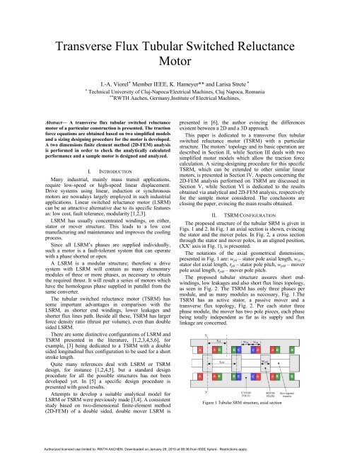
Figure 1 <strong>Tubular</strong> SRM structure, axial section<br />
Authorized licensed use limited to: RWTH AACHEN. Downloaded on January 29, 2010 at 08:38 from IEEE Xplore. Restrictions apply.
Figure 2 <strong>Tubular</strong> SRM structure, XX’ cross section<br />
The mover’s poles are made of soft magnetic composite<br />
materials (SMC) cylinders placed on a shaft which may be<br />
fabricated of non magnetic material. The stator core<br />
construction can be done in different ways. For not so<br />
large motors, the stator can be obtained from four parts,<br />
each one containing a pole and the corresponding parts of<br />
the yoke cylinder. In this case, each part should be made<br />
of SMC and all four assembled in an outer case of<br />
magnetic or nonmagnetic material. The number of stator<br />
modules depends on the required thrust, specified exterior<br />
diameter and total length of the motor. The mover is built<br />
as long as necessary to assure on the entire stroke length<br />
with adequate configuration of its poles.<br />
III. TSRM’S TRACTION FORCE CALCUALTION<br />
The traction force is the main specification for any kind<br />
of linear motor. Consequently, a designed TSRM must<br />
produce a traction force equal or larger than the one<br />
required by the drive system. The main dimensions and<br />
excitation mmf strongly depend on the traction force and<br />
the designer should make the best choices in order to<br />
conform to the imposed specifications and to obtain a<br />
motor which has a good force to volume ratio.<br />
The traction force of a linear motor, TSRM included,<br />
can be calculated analytically or by applying a specific<br />
numerical method as finite differences (FDM) or finite<br />
element (FEM). Nowadays, designing any type of electric<br />
machine consists of four compulsory stages:<br />
i) A sizing designing stage when, based on simplified<br />
models and on existing experience, the main<br />
dimensions and performance are calculated.<br />
ii) A second stage in which, by employing a specific<br />
numerical method, mostly FEM, the previous<br />
calculations are checked and a quasi optimal motor<br />
is obtained.<br />
iii) The third stage is dedicated to the heating-cooling<br />
calculation via FEM or any other method which is<br />
accurate enough, as the one based on thermal<br />
equivalent circuit.<br />
iv) Through the fourth stage, the entire drive system<br />
(supply source-motor-load) is simulated on<br />
Figure 3 Traction force calculation, simplified relay-type structure<br />
computer to check if the dynamic and steady-state<br />
required performances are fulfilled.<br />
Since no specific application is considered in the paper,<br />
only the first two TSRM designing stages are discussed,<br />
more strength being put on the sizing-designing procedure<br />
which has important particularities.<br />
Two models to calculate the TSRM traction force are<br />
used, a simplified linear one and a model based on the<br />
variable equivalent air-gap permeance method, previously<br />
applied to the rotating SRM or to the linear transverse flux<br />
reluctance motor, [7,8,9].<br />
In the first case, a simple structure is considered, with<br />
two identical coils supplied in parallel and producing the<br />
same mmf, Fig. 3.<br />
The magnetic energy in the air-gap Wmg is:<br />
1 Bg<br />
Wmg<br />
= ∫ dv (1)<br />
2 µ 0<br />
where the elemental volume is, function of mover’s<br />
position:<br />
∫ dv = Apx<br />
g = Rgα<br />
( w pM − x)<br />
g<br />
(2)<br />
The traction force fTL results as:<br />
∂Wmg<br />
1 Bg<br />
fTL = = g(<br />
−Rgα<br />
)<br />
∂x<br />
2 µ<br />
i=<br />
ct<br />
1 Rgα<br />
2<br />
fTL<br />
= − µ 0F<br />
(3)<br />
2 g<br />
where the coil mmf, F is:<br />
F = ( 1/<br />
µ 0 ) ⋅ g ⋅ Bg<br />
(4)<br />
The notations are the following: Apx – common stator<br />
and mover pole area, x – axial coordinate, wpM – axial<br />
length of the mover pole, equal to the stator pole axial<br />
length, wpS, g – air-gap length, Rg – stator interior radius in<br />
the air-gap, Bg – peak value of the air-gap flux density in<br />
aligned position, α – stator pole angular length, µ0 – airgap<br />
magnetic permeability.<br />
The force fTL, (3) is constant and does not depend on the<br />
mover, or stator pole axial length, but on square of the coil<br />
Authorized licensed use limited to: RWTH AACHEN. Downloaded on January 29, 2010 at 08:38 from IEEE Xplore. Restrictions apply.<br />
2<br />
2<br />
0
mmf, pole circumferential length in air-gap (Rg α) and airgap<br />
length g.<br />
Considering the actual structure of the TSRM, Fig. 2,<br />
the total traction force developed by a energized phase is:<br />
fTLph<br />
= −(<br />
µ 0 / g)<br />
⋅ F Rgα<br />
(5)<br />
In the case of the variable equivalent permeance model,<br />
the flux linkage comes as, [7,8]<br />
2π<br />
⋅ x<br />
1 + Pcoeff<br />
cos( )<br />
R 2 gα<br />
⋅ w pM<br />
τ pM<br />
λ(<br />
x,<br />
i)<br />
= µ 0 N i<br />
KC<br />
g K s ( x,<br />
i)<br />
(6)<br />
where N is the number of series turns per phase coil, i is<br />
the phase current, g, KC, Pcoeff, τpM are the actual length of<br />
the air-gap, the Carter’s factor, the variable equivalent airgap<br />
permeance coefficient [7,8] and the mover axial pole<br />
pitch. The saturation function KS(x,i) can be given by a<br />
cosinusoidal function as in [3]:<br />
x<br />
K S ( x,<br />
i)<br />
= K S 0[ Acos(<br />
2π<br />
) + B]<br />
(7)<br />
τ PM<br />
where the coefficients A and B are function of phase<br />
current and should be calculated by using the aligned and<br />
unaligned flux linkage versus current characteristics.<br />
For design purpose, in a first sizing-designing stage, the<br />
saturation function can be reduced to a saturation constant<br />
estimated in aligned position, considering the core<br />
material magnetization characteristic (B-H), Fig. 4.<br />
Accordingly, the saturation factor Ks is given by:<br />
K /<br />
2<br />
S = K S0<br />
⋅ Buns<br />
Bsat<br />
(8)<br />
K S0<br />
= 1 + ( 1/<br />
µ r0<br />
) ⋅ ( lco<br />
/ lg<br />
)<br />
(9)<br />
Where Buns, Bsat are the flux density unsaturated and<br />
saturated values, lco, lg are mean length of magnetic path in<br />
the core and in the air-gap respectively, and µr0 is the<br />
initial relative permeability of the core material. The<br />
estimated magnetic field intensity He should be<br />
approximated initially considering that the entire mmf is<br />
producing magnetic field only in the air-gap.<br />
The traction force fTP developed by two opposite coils,<br />
Figure 4 Saturation factor calculation<br />
calculated based on this model, is:<br />
f<br />
TP<br />
i<br />
∂λ<br />
= ∫ di =<br />
∂x<br />
0<br />
µ<br />
0<br />
= −π<br />
g<br />
2<br />
F αRg<br />
pM<br />
τ pM<br />
coeff<br />
KC<br />
K S<br />
The peak and average value of fTP are:<br />
w<br />
f = 2πf<br />
⋅ K<br />
P<br />
2π<br />
⋅ x<br />
sin( )<br />
τ<br />
pM<br />
(10)<br />
TP max TL vp<br />
(11)<br />
f = 4 f ⋅ K<br />
(12)<br />
TPav TL vp<br />
where the variable permeance factor Kvp is:<br />
w<br />
P<br />
pM coeff<br />
K vp = (13)<br />
τ pM KC<br />
K S<br />
Equations (10)-(12) remain valid for a phase, by simply<br />
replacing fTL with fTLph.<br />
IV. SIZING-DESIGNING PROCEDURE<br />
The Dg 2 L equation, where Dg and L are the average airgap<br />
diameter and respectively the stack length, is the most<br />
used one to size rotating electric machines. This equation,<br />
written for motor operation, relates power output Pout and<br />
rotor speed n to the rotor volume, through an output<br />
general coefficient Ksiz, which contains air-gap flux<br />
density Bg, electrical loading A, energy conversion<br />
parameters, number of pole pairs and some sizing<br />
coefficients specific to each type of motor [9,10].<br />
In the case of linear electric machines, the sizing should<br />
start from the traction force equation, which relates the<br />
produced thrust to air-gap flux density, main dimensions<br />
and some coefficients that should be estimated based on<br />
existing experience and data collected from similar motors<br />
already built. In the specific case of TSRM, the sizing<br />
equation would be (12), which can be conveniently<br />
arranged as:<br />
4<br />
w<br />
P<br />
pM coeff 2<br />
fTPav = f =<br />
Bg<br />
⋅ g ⋅αR<br />
g (14)<br />
µ 0 τ pM KC<br />
K S<br />
evincing the constants and the coefficients to be estimated.<br />
Carter’s factor KC and permeance coefficient Pcoeff are<br />
function of the air-gap length to mover pole pitch g/τpM<br />
and mover pole axial length to mover pole pitch, wpM/τpM,<br />
ratios [8,9]:<br />
K<br />
C<br />
1<br />
= (15)<br />
1 − γ ( g / τ )<br />
pM<br />
4 ⎛<br />
⎞<br />
⎜ γ g π<br />
P = ⋅ ⋅ sin ⋅ ⋅ ⎟<br />
coeff β R KC<br />
(16)<br />
π ⎜<br />
⎟<br />
⎝ β τ pM 2<br />
⎠<br />
Authorized licensed use limited to: RWTH AACHEN. Downloaded on January 29, 2010 at 08:38 from IEEE Xplore. Restrictions apply.
4 ⎛<br />
⎫<br />
( ) ⎛ 2<br />
γ =<br />
⎞<br />
⎜u<br />
⋅ atn u − ln<br />
⎞<br />
⎜ 1+<br />
u ⎟⎟<br />
⎪<br />
π ⎝<br />
⎝ ⎠⎠<br />
⎪<br />
2<br />
⎪<br />
( 1−<br />
f )<br />
⎪<br />
β =<br />
2<br />
⎬ (17)<br />
2(<br />
1+<br />
f )<br />
⎪<br />
1−<br />
w /<br />
⎪<br />
pM τ pM<br />
2<br />
u =<br />
, f = u + 1+<br />
u ⎪<br />
2g<br />
/ τ pM<br />
⎪<br />
⎭<br />
They can be estimated initially to be introduced in (14)<br />
as will be KS (8),(9) and should be calculated based on the<br />
motor dimensions for a second iteration in the sizingdesigning<br />
procedure.<br />
The ratio of the rotor pole axial length to rotor pole<br />
pitch is usually 1/3 since the mover pole axial length is<br />
equal to the stator pole axial length and to the stator slot<br />
axial length wsS.<br />
The peak air-gap flux density Bg value should be as<br />
large as possible, function of core material, and has to be<br />
choose initially. It results that the product g·Rg·α can be<br />
obtained from (14), where α
v) With data obtained through the sizing step, the<br />
parameters and performances can now be<br />
calculated.<br />
The final dimensions and main data will be fixed only<br />
after a FEM analysis, when the force versus mover<br />
position and stator mmf is calculated and the flux density<br />
through different parts of TSRM iron core checked.<br />
V. 2D-FEM ANALYSIS<br />
The TSRM magnetic field has a true 3D pattern, but it<br />
can be calculated by combining two 2D structures. Since<br />
there is not any problem concerning the 3D-FEM analysis<br />
for the TSRM, here will be further discussed only the<br />
combination which should be made in order to obtain the<br />
adequate solution of the 3D problem by employing two<br />
2D configurations.<br />
The first 2D-FEM analysis is performed through a cross<br />
section of TSRM in aligned position, Fig. 2, all four coils<br />
being energized. This is a natural structure and allows for<br />
the peak flux density values calculation in the air-gap and<br />
in the stator and rotor iron core. That is an important<br />
calculation since it gives information about the level of<br />
saturation obtained in the iron core.<br />
The second 2D structure considered is presented in Fig.<br />
6. It consists of two stator pole pieces and two rotor poles,<br />
all in a rectangular form. An exterior structure, for closing<br />
the flux lines is considered too. The stator and mover<br />
poles have the same axial pole length and pitch as the<br />
actual motor. The stator pole thickness on the z direction<br />
is equal with the actual motor poles circumferential width<br />
Figure 6 TSRM, axial 2D structure and FEM obtained flux lines<br />
Figure 7 Sample TSRM, mmf per coil<br />
Figure 8 Sample TSRM, tangential force per pair of coils<br />
and this is kept the same for rotor poles and for the stator<br />
frame that closes the flux path.<br />
An equivalent coil mmf is taken in order to obtain in<br />
the aligned position the same air-gap flux density value, as<br />
the one calculated via 2D-FEM in a cross section with<br />
only two opposite coils energized.<br />
VI. CALCULATED RESULTS<br />
In the following, typical results for the quasi optimal<br />
calculation in the case of a sample TSRM are given. The<br />
traction force per module is 100N and the chosen values<br />
are: peak air-gap flux density Bg = 1.6T, current density J<br />
Figure 9 Sample TSRM,2D-FEM analysis in a cross section<br />
Figure 10 Sample TSRM, tangential force<br />
Authorized licensed use limited to: RWTH AACHEN. Downloaded on January 29, 2010 at 08:38 from IEEE Xplore. Restrictions apply.
= 5·10 6 A/m 2 , air-gap total length g = 1.5 mm, slot fill<br />
factor Kfill = 0.4, saturation coefficient KS = 1.4, Carter’s<br />
factor KC = 1.6, air-gap equivalent permeance coefficient<br />
Pcoeff=1.3, mover pole axial length per pole pitch<br />
wpM/τpM=1/3.<br />
The necessary area of the stator slot (18) is Asl =<br />
0.19·10 -2 m 2 and the required mmf per coil (4) is<br />
F=1900A.<br />
From (14) comes the pole circumferential length<br />
Rg·α=4.22·10 -2 m·rad. If Rg = 0.05m, then the minimum α<br />
value results 48.46 deg.<br />
Considering now α as variable and y as parameter, for<br />
the given sample TSRM, the coil mmf and the tangential<br />
force variation characteristics are given in Figs. 7 and 8.<br />
In this case, if y = 50mm, the exterior radius is Rex =<br />
125mm, the stator yoke height being 25mm.<br />
The force density results:<br />
f<br />
den<br />
=<br />
f<br />
Tph<br />
Vol<br />
84<br />
=<br />
2.<br />
945⋅10<br />
−3<br />
= 28.<br />
52 ⋅10<br />
N / m<br />
3<br />
3<br />
(22)<br />
where the total force per phase fTph is calculated via 2D-<br />
FEM analysis and Vol is the phase volume. Even for a<br />
first draft, as it is the designed TSRM, the force density is<br />
quite impressive.<br />
The computational process should stop when the<br />
required force is obtained with the minimum volume,<br />
which means in fact the minimum value of Rg. An<br />
adequate program can be developed and a lot of variants<br />
calculated in extremely short time.<br />
In Fig. 9, the 2D-FEM results obtained in a cross<br />
section, with Rg=0.05m and y=0.05m are given. In Fig. 10<br />
is given the traction force calculated via 2D-FEM<br />
simplified model, Fig. 6, in comparison with the values<br />
calculated by using the variable equivalent permeance<br />
method.<br />
As can be seen from the characteristics presented in<br />
Fig. 10, the simplified model based on variable equivalent<br />
air-gap permeance covers quite well the phenomena. The<br />
differences that exist are caused by the saturation effect<br />
which is not entirely considered in the model.<br />
VII. CONCLUSIONS<br />
A transverse flux tubular switched reluctance motor of<br />
a particular construction is introduced. Such a motor can<br />
be a good solution for short track transfer system drives<br />
due to its good performance and high thrust to volume<br />
ratio.<br />
A novel sizing-design procedure is developed for<br />
TSRM based on traction force equation and simplified<br />
magnetic equivalent circuit calculations. The 2D-FEM<br />
analysis is employed to check the analytical calculated<br />
values. The 2D-FEM analysis is performed on two<br />
models, a cross section through an aligned natural position<br />
and an axial section specially defined to calculate the trust<br />
versus mover displacement at different values of the phase<br />
mmf.<br />
The sizing-design procedure is applied on a sample<br />
TSRM. The motor traction force is calculated via 2D-<br />
FEM, as are calculated the flux density values in the airgap<br />
and stator and mover core for aligned position and<br />
different phase mmf.<br />
A quasi optimal TSRM, concerning the best thrust to<br />
volume ratio can be obtained via the proposed algorithm<br />
too.<br />
REFERENCES<br />
[1] R.Krishnan, <strong>Switched</strong> <strong>Reluctance</strong> <strong>Motor</strong> Drives Modeling,<br />
Simulation, Analysis, Design and Applications, CRC Press,<br />
London 2001.<br />
[2] I. Boldea, S.A. Nasar, Linear Electric Actuators and Generators,<br />
Cambridge Univ. Press, U.K., 1977<br />
[3] J. Corde, M.Wilkinson, „Prediction and measurement of magnetic<br />
parameters of cylindrical linear switched reluctance actuator“,<br />
Proc.Int.Conf.Electrical Machines, vol.3, Paris, France, Sept 1994,<br />
pp.479-484.<br />
[4] W.-C. Gan, N.C.Cheung, “Design of linear switched reluctance<br />
motor for high precision applications” ,Proc. 2001 IEEE Int.<br />
Electric Machines and Drives Conf., pp.701-704<br />
[5] B.-S. Lee, H.-K. Bae, P.Vijayraghavan, R.Krishnan, “Design of a<br />
linear switched reluctance machine”, IEEE Trans. Ind. Appl.,<br />
vol.36, no.6, pp.1571-1580, Nov./Dec.2000<br />
[6] U.Deshpande, “Two-dimensional finite-element analysis of a high<br />
force density linear switched reluctance machine including threedimensional<br />
effects” IEEE Trans. Ind. Appl., vol.36, no.4,<br />
pp.1047-1052, July/Aug. 2000<br />
[7] J.H. Chang, D.H. Kang, I-A. Viorel, Larisa, Strete, “<strong>Transverse</strong><br />
flux reluctance linear motor’s analytical model based on finite<br />
element method analysis results”, IEEE Trans. on Magnetics,<br />
vol.43, no.4, pp.1201-1204, April 2007<br />
[8] J.H. Chang, D.H. Kang, I.-A. Viorel, Tomescu Ilinca, Strete<br />
Larisa, “Saturated double salient reluctance motors”, ICEM 2006,<br />
Greece, PTA2-12, on CD-ROM, Summaries volume pg. 530<br />
[9] G. Henneberger, I.-A. Viorel: Variable <strong>Reluctance</strong> Electrical<br />
Machines. Shaker Verlag, Aachen, Germany, 2001<br />
[10] V.B.Hosinger, “Sizing equation for electrical machinery”, IEEE<br />
Trans. Energy Conversion, vol.2, no.1, pp.116-121, March 1987<br />
Authorized licensed use limited to: RWTH AACHEN. Downloaded on January 29, 2010 at 08:38 from IEEE Xplore. Restrictions apply.


