Simulation of a High Voltage System in a Hybrid Electrical Vehicle
Simulation of a High Voltage System in a Hybrid Electrical Vehicle
Simulation of a High Voltage System in a Hybrid Electrical Vehicle

Create successful ePaper yourself
Turn your PDF publications into a flip-book with our unique Google optimized e-Paper software.
2010, 12th International Conference on Optimization <strong>of</strong> <strong>Electrical</strong> and Electronic Equipment, OPTIM 2010<br />
<strong>Simulation</strong> <strong>of</strong> a <strong>High</strong> <strong>Voltage</strong> <strong>System</strong> <strong>in</strong> a<br />
<strong>Hybrid</strong> <strong>Electrical</strong> <strong>Vehicle</strong><br />
Rüdiger Appunn and Kay Hameyer<br />
Institute <strong>of</strong> <strong>Electrical</strong> Mach<strong>in</strong>es, RWTH Aachen University<br />
ruediger.appunn@iem.rwth-aachen.de, kay.hameyer@iem.rwth-aachen.de<br />
Abstract-In modern hybrid electrical vehicles (HEV) the<br />
electrical system <strong>in</strong>cludes different voltage levels.<br />
Visualization <strong>of</strong> the electric quantities such as currents and<br />
voltages <strong>of</strong> a high voltage system under load conditions is<br />
presented <strong>in</strong> this paper. Different strategies <strong>of</strong> electric<br />
component model<strong>in</strong>g such as mach<strong>in</strong>es or power electronics<br />
are used for an <strong>in</strong>tensive analysis <strong>of</strong> the electrical system.<br />
Evaluation <strong>of</strong> the DC-l<strong>in</strong>k with respect to transients and<br />
feedbacks result<strong>in</strong>g from operational performance or fault<br />
operation is done.<br />
Keywords-hybrid electrical vehicle (HEV), vehicle<br />
electrical system, high voltage system, electric component<br />
model<strong>in</strong>g, voltage transients, DC-l<strong>in</strong>k<br />
I. INTRODUCTION<br />
Nowadays an <strong>in</strong>creas<strong>in</strong>g number <strong>of</strong> (hybrid) electrical<br />
vehicles are fabricated. New challenges regard<strong>in</strong>g<br />
reliability and safety arise as high voltage systems are<br />
used <strong>in</strong> new generations <strong>of</strong> vehicles. Observ<strong>in</strong>g currents<br />
and voltages <strong>in</strong> electrical systems <strong>of</strong> HEV dur<strong>in</strong>g<br />
operation is essential for the performance and stable<br />
operation <strong>of</strong> the vehicle. Detailed system simulation is<br />
presented here to exam<strong>in</strong>e these parameters. This paper<br />
focuses on the visualization <strong>of</strong> dynamic behavior <strong>of</strong><br />
voltages and currents result<strong>in</strong>g from the operation <strong>of</strong> the<br />
vehicle. Hereby <strong>in</strong>fluences on s<strong>in</strong>gle system components<br />
can be evaluated and a life cycle analysis is supported.<br />
Components <strong>of</strong> the electrical system can be described by<br />
their transfer functions. This signal flow oriented method<br />
<strong>of</strong> simulation can be found <strong>in</strong> literature [1]. Another<br />
approach to model the system components is the use <strong>of</strong><br />
electric equivalent circuits [2]. A comb<strong>in</strong>ation <strong>of</strong> both<br />
methods, which exploits the advantages <strong>of</strong> both, is<br />
presented <strong>in</strong> this work.<br />
II. INFORMATION<br />
A. Topology <strong>of</strong> the vehicle electrical system<br />
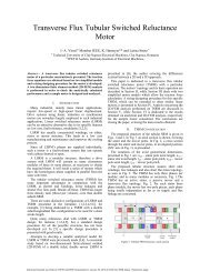
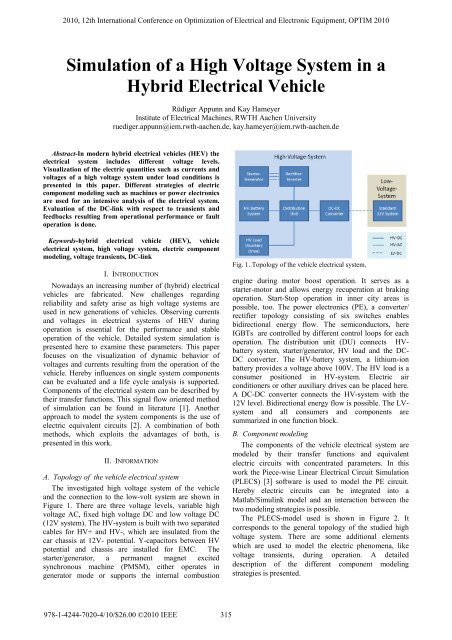
The <strong>in</strong>vestigated high voltage system <strong>of</strong> the vehicle<br />
and the connection to the low-volt system are shown <strong>in</strong><br />
Figure 1. There are three voltage levels, variable high<br />
voltage AC, fixed high voltage DC and low voltage DC<br />
(12V system). The HV-system is built with two separated<br />
cables for HV+ and HV-, which are <strong>in</strong>sulated from the<br />
car chassis at 12V- potential. Y-capacitors between HV<br />
potential and chassis are <strong>in</strong>stalled for EMC. The<br />
starter/generator, a permanent magnet excited<br />
synchronous mach<strong>in</strong>e (PMSM), either operates <strong>in</strong><br />
generator mode or supports the <strong>in</strong>ternal combustion<br />
978-1-4244-7020-4/10/$26.00 '2010 IEEE<br />
315<br />
Fig. 1. Topology <strong>of</strong> the vehicle electrical system.<br />
eng<strong>in</strong>e dur<strong>in</strong>g motor boost operation. It serves as a<br />
starter-motor and allows energy recuperation at brak<strong>in</strong>g<br />
operation. Start-Stop operation <strong>in</strong> <strong>in</strong>ner city areas is<br />
possible, too. The power electronics (PE), a converter/<br />
rectifier topology consist<strong>in</strong>g <strong>of</strong> six switches enables<br />
bidirectional energy flow. The semiconductors, here<br />
IGBTs are controlled by different control loops for each<br />
operation. The distribution unit (DU) connects HVbattery<br />
system, starter/generator, HV load and the DC-<br />
DC converter. The HV-battery system, a lithium-ion<br />
battery provides a voltage above 100V. The HV load is a<br />
consumer positioned <strong>in</strong> HV-system. Electric air<br />
conditioners or other auxiliary drives can be placed here.<br />
A DC-DC converter connects the HV-system with the<br />
12V level. Bidirectional energy flow is possible. The LVsystem<br />
and all consumers and components are<br />
summarized <strong>in</strong> one function block.<br />
B. Component model<strong>in</strong>g<br />
The components <strong>of</strong> the vehicle electrical system are<br />
modeled by their transfer functions and equivalent<br />
electric circuits with concentrated parameters. In this<br />
work the Piece-wise L<strong>in</strong>ear <strong>Electrical</strong> Circuit <strong>Simulation</strong><br />
(PLECS) [3] s<strong>of</strong>tware is used to model the PE circuit.<br />
Hereby electric circuits can be <strong>in</strong>tegrated <strong>in</strong>to a<br />
Matlab/Simul<strong>in</strong>k model and an <strong>in</strong>teraction between the<br />
two model<strong>in</strong>g strategies is possible.<br />
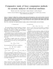
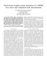
The PLECS-model used is shown <strong>in</strong> Figure 2. It<br />
corresponds to the general topology <strong>of</strong> the studied high<br />
voltage system. There are some additional elements<br />
which are used to model the electric phenomena, like<br />
voltage transients, dur<strong>in</strong>g operation. A detailed<br />
description <strong>of</strong> the different component model<strong>in</strong>g<br />
strategies is presented.
Fig. 2. HV-system modeled <strong>in</strong> PLECS<br />
For the Starter/Generator a PMSM-model <strong>in</strong> dq-axis is<br />
applied. The differential equations, <strong>of</strong> this system are<br />
di u<br />
⋅ ω<br />
d<br />
d<br />
Td + id<br />
= + ⋅Tq<br />
⋅iq<br />
dt R1<br />
di<br />
u<br />
ω ⋅ L<br />
q<br />
q<br />
hd<br />
T q ⋅ + iq<br />
= − ω ⋅Td<br />
⋅id<br />
− ⋅i′<br />
F 0<br />
dt R1<br />
R1<br />
J dω<br />
⋅ = p ⋅ 0<br />
p dt<br />
L<br />
where<br />
d Td<br />
= and T<br />
R<br />
[ i′<br />
F ⋅ Lhd<br />
− id<br />
⋅(<br />
Lq<br />
− Ld<br />
) ] ⋅iq<br />
− MW<br />
1<br />
q =<br />
Lq<br />
.<br />
R<br />
1<br />
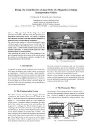
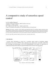
These mach<strong>in</strong>e equations are implemented <strong>in</strong> a block<br />
diagram <strong>in</strong> the Simul<strong>in</strong>k environment (Figure 3) and<br />
<strong>in</strong>teract with the circuit simulator by controll<strong>in</strong>g the<br />
current sources <strong>of</strong> the mach<strong>in</strong>e model. Figure 4 shows the<br />
Fig. 3. Dynamic mach<strong>in</strong>e model <strong>of</strong> a PMSM <strong>in</strong> Simul<strong>in</strong>k.<br />
(1)<br />
(2)<br />
(3)<br />
316<br />
current sources Ia and Ic, which impress the stator<br />
currents from the mach<strong>in</strong>e model to the clamps <strong>of</strong> its<br />
representation <strong>in</strong> the electric circuit environment. The<br />
phase to phase voltages are measured here as well and<br />
serve as <strong>in</strong>puts for the mach<strong>in</strong>e equations <strong>in</strong> the Simul<strong>in</strong>k<br />
environment.<br />
For accurate simulation <strong>of</strong> the generator mode <strong>in</strong><br />
dynamic operation, the <strong>in</strong>ternal combustion eng<strong>in</strong>e (ICE)<br />
is modeled, too. By us<strong>in</strong>g the Matlab toolbox<br />
SimDrivel<strong>in</strong>e, it is possible to model the mechanical<br />
drive tra<strong>in</strong> components and couple them with the<br />
electrical mach<strong>in</strong>e model. The ICE is simulated by a<br />
lookup table which determ<strong>in</strong>es the torque applied to the<br />
shaft depend<strong>in</strong>g on torque demands regard<strong>in</strong>g the actual<br />
speed <strong>of</strong> the motor. It is possible to def<strong>in</strong>e additional<br />
torques and moments <strong>of</strong> <strong>in</strong>ertia. In this way the complete,<br />
hybrid drive tra<strong>in</strong> can be modeled. Figure 5 presents the<br />
mechanical drive tra<strong>in</strong> modeled <strong>in</strong> Simul<strong>in</strong>k.<br />
The power electronics is simulated by switch<strong>in</strong>g<br />
devices and freewheel<strong>in</strong>g diodes (Figure 6). In this<br />
simulation IGBTs are used. Control loops at the Simul<strong>in</strong>k<br />
environment control the semiconductor switches via<br />
Space Vector Modulation [4,5].<br />
The dynamic battery model is based on a modified<br />
Theven<strong>in</strong> model [6]. Figure 7 shows the electric<br />
equivalent circuit. It consists <strong>of</strong> the open-circuit voltage<br />
source U0, the <strong>in</strong>ner resistance Ri, a parallel RC-element<br />
simulat<strong>in</strong>g transient behavior and the series <strong>in</strong>ductance Li<br />
<strong>of</strong> the contacts. The <strong>Voltage</strong> U0 is depend<strong>in</strong>g on the state<br />
<strong>of</strong> charge (SOC) <strong>of</strong> the battery. Equation 4 def<strong>in</strong>es the<br />
SOC <strong>of</strong> the battery:<br />
SOC<br />
C − Q<br />
C<br />
Dis = (4)<br />
Where C is the Capacity and QDis the discharged<br />
electrical charge <strong>of</strong> the battery. The voltage <strong>of</strong> one Li-Ion<br />
cell <strong>in</strong> function <strong>of</strong> the SOC is presented <strong>in</strong> Figure 8 [7].<br />
The battery consists <strong>of</strong> 33 cells. Transient charg<strong>in</strong>g/<br />
discharg<strong>in</strong>g phenomena can be simulated.
Fig. 4. <strong>Voltage</strong> controlled current sources represent<strong>in</strong>g the<br />
PMSM <strong>in</strong> the circuit simulator.<br />
The load <strong>in</strong> the HV-system is an auxiliary drive, for<br />
<strong>in</strong>stance an electrical climate control unit. A PMSM<br />
mach<strong>in</strong>e model and a pulse-controlled <strong>in</strong>verter are<br />
implemented <strong>in</strong> this simulation. Similar model<strong>in</strong>g<br />
strategies for the electrical mach<strong>in</strong>e and the PE are<br />
utilized. Variable load cases can be simulated and<br />
studied.<br />
The DC-DC converter consists <strong>of</strong> a high frequency<br />
switch<strong>in</strong>g unit <strong>in</strong>clud<strong>in</strong>g a transformer to separate the<br />
two voltage levels [8,9,10]. Figure 9 shows its<br />
topology. A filter capacitor on each side reduces<br />
voltage ripples <strong>in</strong> the DC-l<strong>in</strong>k. The 12V load is be<strong>in</strong>g<br />
characterized by a load resistor Rload. S<strong>in</strong>ce the focus<br />
<strong>of</strong> this vehicle electrical system simulation<br />
concentrates on the HV-system, this simplification is<br />
appropriate.<br />
Power cables <strong>in</strong> the vehicle are simulated us<strong>in</strong>g πequivalent<br />
circuits with l<strong>in</strong>e resistance, leakage<br />
<strong>in</strong>ductance and capacitance to the car chassis (Figure<br />
10). Herewith model<strong>in</strong>g <strong>of</strong> transients <strong>in</strong> the cable<br />
harness dur<strong>in</strong>g dynamic operation is possible [11].<br />
The peripheral l<strong>in</strong>e represents the vehicle body at<br />
LV-DC m<strong>in</strong>us potential. Due to possible leakage<br />
currents to other electrical components <strong>of</strong> the vehicle,<br />
the car chassis is part <strong>of</strong> the model. Figure 11 shows<br />
the standardized structure <strong>of</strong> the <strong>in</strong>terconnection from a<br />
HV-component to vehicle chassis. Y-capacitors and<br />
<strong>in</strong>sulation resistances which can be reduced by<br />
switches are implemented.<br />
Event ports can be used to simulate deviations from<br />
regular operation, such as load dumps. They are<br />
standardized and control the switches which reduce<br />
component parameters or change the electric circuit.<br />
Fig. 5. Representation <strong>of</strong> the mechanical drive tra<strong>in</strong> modeled<br />
<strong>in</strong> Simul<strong>in</strong>k.<br />
317<br />
Fig. 6. Power electronics circuit <strong>in</strong> the HV-system.<br />
C. Control<br />
Control loops are implemented <strong>in</strong> the Simul<strong>in</strong>k level.<br />
Torque and speed control for the starter/generator <strong>in</strong><br />
motor operation or additional drives <strong>in</strong> the HV-<strong>System</strong><br />
is realized by us<strong>in</strong>g field oriented control strategies.<br />
Figure 12 shows the implemented speed control. A<br />
cascade control <strong>of</strong> current and speed is used to adjust<br />
the speed. Hereby a dynamic load for the vehicle<br />
electrical system is simulated.<br />
In generator operation the term<strong>in</strong>al voltage <strong>of</strong> the<br />
starter/generator (a PMSM) must be controlled by the<br />
power electronics, s<strong>in</strong>ce no excitation current can be<br />
modified. Here an active rectify<strong>in</strong>g method to control<br />
the charg<strong>in</strong>g current based on [12] and [13] is used.<br />
Provided that symmetric three phase s<strong>in</strong>usoidal<br />
currents<br />
⎡<br />
⎤<br />
⎡i<br />
⎤ ⎢ cosωt<br />
⎥<br />
R<br />
⎢ ⎥ ⎢ 2π<br />
⎥<br />
⎢<br />
i<br />
⎥<br />
= I ⋅ ⎢cos(<br />
ωt<br />
− ) ⎥<br />
(5)<br />
S<br />
⎢ ⎥ ⎢ 3 ⎥<br />
⎣iT<br />
⎦ ⎢ 2π<br />
cos( ωt<br />
+ ) ⎥<br />
⎢⎣<br />
3 ⎥⎦<br />
exists <strong>in</strong> the stator w<strong>in</strong>d<strong>in</strong>gs, all harmonics are<br />
neglected and no saturation occurs, two phase currents<br />
have to be measured and transformed to an orthogonal<br />
system to calculate the current amplitude. The<br />
follow<strong>in</strong>g transformation is used:<br />
⎡iA<br />
⎤ ⎡iR<br />
⎤<br />
⎢ ⎥ = T32<br />
⎢ ⎥<br />
⎣iB<br />
⎦ ⎣iS<br />
⎦<br />
⎡ 3 ⎤<br />
⎢ 0 ⎥<br />
T = ⎢ 2<br />
32<br />
⎥<br />
⎢ 1<br />
2⎥<br />
⎢⎣<br />
2 ⎥⎦<br />
(6)<br />
Fig. 7. Battery model based on Theven<strong>in</strong> equivalent<br />
circuit[6].
Fig. 8. No load voltage-state <strong>of</strong> charge characteristic <strong>of</strong> one<br />
Li-Ion cell [7].<br />
From the orthogonal system the amplitude is<br />
determ<strong>in</strong>ed via a dq-transformation:<br />
⎡id<br />
⎤ ⎡iA<br />
⎤<br />
⎢ ⎥ = Tα<br />
⎢ ⎥<br />
⎣iq<br />
⎦ ⎣iB<br />
⎦<br />
(7)<br />
⎡ cos( α)<br />
s<strong>in</strong>( α)<br />
⎤<br />
Tα<br />
= ⎢<br />
⎥<br />
⎣−<br />
s<strong>in</strong>( α)<br />
cos( α)<br />
⎦<br />
i<br />
Where<br />
B<br />
α = ωt<br />
= arctan .<br />
iA<br />
<br />
The result is that id = I , the current amplitude and<br />
i q = 0 .<br />
The actual voltage control is applied by a cascade<br />
control. An outer voltage loop compares the DC-l<strong>in</strong>k<br />
with the desired voltage and serves as <strong>in</strong>put for a PIcontroller.<br />
Its output is added to the DC current,<br />
compared with the calculated current amplitude I and<br />
given to a PI-controller as well, this is the <strong>in</strong>ner current<br />
−1<br />
control loop. By us<strong>in</strong>g the <strong>in</strong>verse transformations T α<br />
−1<br />
and T the control output can be transformed to three<br />
32<br />
phase values and the semiconductor switches are<br />
controlled via pulse width modulation. Figure 13<br />
shows the control topology.<br />
Fig. 9. Bidirectional DC-DC converter.<br />
318<br />
Fig. 10. π-equivalent circuit <strong>of</strong> HV-cable segment.<br />
The bidirectional DC-DC converter has a closed loop<br />
control for energy flow from HV-system to the 12V<br />
system. It works as a step-down converter with<br />
additional PID controller. This is the nom<strong>in</strong>al operation<br />
mode, s<strong>in</strong>ce the starter/generator powers the low<br />
voltage system. For reverse energy flow the converter<br />
operates <strong>in</strong> step-up mode. An open loop controlled is<br />
implemented. This control method is sufficient, s<strong>in</strong>ce<br />
only <strong>in</strong> fault cases the LV-system has to supply the<br />
HV-system. Figure 14 depicts the ma<strong>in</strong> control circuit.<br />
D. <strong>Simulation</strong><br />
Depend<strong>in</strong>g on the particular drive cycle <strong>of</strong> the HEV<br />
several operation modes <strong>of</strong> the starter/generator are<br />
studied. Generator mode at vary<strong>in</strong>g speed and boost<br />
cycles with torque demands are considered. Start-stop<br />
mode and recuperative break<strong>in</strong>g are implemented <strong>in</strong><br />
the model. Different operat<strong>in</strong>g conditions and their<br />
effects on the HV-DC l<strong>in</strong>k are simulated as well. Turn<br />
on, turn <strong>of</strong>f (under load), dynamic load fluctuation,<br />
voltage and current ripples caused from HV<br />
components and state <strong>of</strong> charge HV-battery system<br />
variations are considered. Deviations from such<br />
operation conditions are studied. Here, transients<br />
result<strong>in</strong>g from a load dump or deterioration effects can<br />
be simulated by ideal switches or parameter variation.<br />
Coupl<strong>in</strong>g effects between the voltage levels are<br />
simulated as well. By these simulations a detailed<br />
evaluation <strong>of</strong> the HV-DC l<strong>in</strong>k with respect to voltage<br />
oscillations and <strong>in</strong>ternal feedbacks is possible. Four<br />
simulation results <strong>of</strong> fault situations are presented <strong>in</strong><br />
the follow<strong>in</strong>g paragraphs. The parameters <strong>of</strong> a topical<br />
hybrid electrical vehicle with a nom<strong>in</strong>al DC-l<strong>in</strong>k<br />
voltage <strong>of</strong> above 100V are used.<br />
Fig. 11. Model<strong>in</strong>g <strong>of</strong> the chassis.
Fig. 12. Speed control <strong>of</strong> the PMSM.<br />
1) S<strong>in</strong>gle <strong>in</strong>sulation fault <strong>in</strong> the HV-system<br />
Due to the fact, that the HV-system is built with two<br />
separated cables electrically <strong>in</strong>sulated from the car<br />
chassis, a s<strong>in</strong>gle <strong>in</strong>sulation error does not cause a<br />
breakdown <strong>of</strong> the DC-l<strong>in</strong>k circuit. In Figure 15 the<br />
fault case occurs at 0.15 seconds. The former<br />
symmetric potentials <strong>of</strong> HV+ and HV- displace <strong>in</strong><br />
positive direction. It can be seen that the DC-l<strong>in</strong>k<br />
voltage rema<strong>in</strong>s constant. So a s<strong>in</strong>gle <strong>in</strong>sulation fault is<br />
not critical for stable operation <strong>of</strong> the HV-system<br />
(<strong>in</strong>sulated grid). The problem is that now HV- potential<br />
is connected to the car chassis and to 12V- potential.<br />
For safety issues the s<strong>in</strong>gle <strong>in</strong>sulation fault is critical<br />
and has to be detected.<br />
2) Short circuit fault <strong>in</strong> DC-l<strong>in</strong>k circuit<br />
Switch<strong>in</strong>g errors <strong>in</strong> power electronics or wrong<br />
ma<strong>in</strong>tenance can lead to short circuit faults <strong>in</strong> the HVsystem.<br />
In Figure 16 the DC-l<strong>in</strong>k is short circuited at<br />
0.15 seconds. The voltage decreases immediately and a<br />
high short circuit current occurs. Due to π-element<br />
cable model<strong>in</strong>g, small oscillations can be regarded. The<br />
complete vehicle electrical system simulation can<br />
monitor currents and voltages on all components.<br />
Herby the <strong>in</strong>fluence <strong>of</strong> the fault case to other<br />
components <strong>of</strong> the electrical system can be visualized.<br />
Dimension<strong>in</strong>g <strong>of</strong> component parameters regard<strong>in</strong>g<br />
safety aspects is possible hereby.<br />
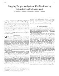
3) Contactor fault dur<strong>in</strong>g battery charg<strong>in</strong>g<br />
Open the mechanical contactors <strong>of</strong> the battery dur<strong>in</strong>g<br />
charg<strong>in</strong>g process leads to transient effects <strong>in</strong> the HVsystem<br />
s<strong>in</strong>ce too much energy is delivered to the<br />
system. Figure 17 presents DC-l<strong>in</strong>k voltage and<br />
Fig. 13. Active rectify<strong>in</strong>g control.<br />
319<br />
Fig. 14. Control <strong>of</strong> the bidirectional DC-DC converter.<br />
charg<strong>in</strong>g current dur<strong>in</strong>g fault operation. The current<br />
decl<strong>in</strong>es under strong oscillation to zero. The voltage<br />
oscillates and returns to the nom<strong>in</strong>al value. The<br />
transient process is ma<strong>in</strong>ly <strong>in</strong>fluenced by parameters <strong>of</strong><br />
the π-element cable model and the battery model itself.<br />
Here, both mechanical contactors open simultaneously.<br />
A s<strong>in</strong>gle contactor fault can be considered and<br />
simulated, as well. The process <strong>of</strong> reconnection <strong>of</strong> the<br />
battery term<strong>in</strong>als dur<strong>in</strong>g operation <strong>of</strong> the HV-system is<br />
another critical case, s<strong>in</strong>ce transient reactions <strong>of</strong><br />
voltage and currents are expected.<br />
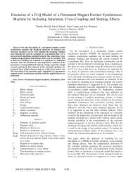
4) Influences <strong>of</strong> a HV-AC <strong>in</strong>sulation fault to the<br />
HV-DC system<br />
An <strong>in</strong>sulation fault <strong>of</strong> one <strong>of</strong> the cables connect<strong>in</strong>g the<br />
starter/generator with the power electronic circuit<br />
affects the HV-DC system. The error current can<br />
circulate via the car chassis, Y-capacitors and power<br />
electronics. Figure 18 depicts the error current<br />
measured directly beh<strong>in</strong>d the fault location. The shape<br />
<strong>of</strong> the current strongly depends on the cable<br />
parameters, the Y-capacitors and the actual switch<strong>in</strong>g<br />
condition <strong>of</strong> the power electronics. Regard<strong>in</strong>g safety<br />
and efficiency <strong>of</strong> the HV-system these currents has to<br />
be monitored. By this simulation the cross coupl<strong>in</strong>g<br />
between the different voltage levels can be analyzed.<br />
Influences to vehicle components <strong>in</strong> the different<br />
system parts are <strong>in</strong> focus <strong>of</strong> research .<br />
Fig. 15. Potentials <strong>of</strong> the DC-l<strong>in</strong>k dur<strong>in</strong>g s<strong>in</strong>gle <strong>in</strong>sulation<br />
fault.
Fig. 16. Results <strong>of</strong> a short circuit fault to the DC-l<strong>in</strong>k.<br />
Fig. 17. Contactor fault dur<strong>in</strong>g battery charg<strong>in</strong>g.<br />
Fig. 18. Error current after HV-AC <strong>in</strong>sulation fault.<br />
III. CONCLUSIONS<br />
This paper presents a comb<strong>in</strong>ed method for the<br />
simulation <strong>of</strong> the dynamic behavior <strong>of</strong> electric voltages<br />
and currents <strong>in</strong> vehicle electrical systems dur<strong>in</strong>g<br />
operation. The system topology is characterized.<br />
Component model<strong>in</strong>g by us<strong>in</strong>g electric equivalent<br />
circuits and transfer functions is discussed. The use <strong>of</strong><br />
the circuit simulator PLECS is proposed to comb<strong>in</strong>e<br />
power electronic circuits with the simulation<br />
environment used. By this procedure, advantages <strong>of</strong><br />
both s<strong>of</strong>tware systems can be used. Various operat<strong>in</strong>g<br />
conditions and the implication on the vehicle electrical<br />
system can be simulated. The simulation results<br />
presented <strong>in</strong> this paper show deviations from the<br />
regular operation. Transient voltages, high short circuit<br />
320<br />
currents or error currents result<strong>in</strong>g from <strong>in</strong>sulation<br />
faults are simulated <strong>in</strong> this way. Other critical fault<br />
scenarios as load dumps can be analyzed as well. This<br />
fault situations are used for reliability and safety issues.<br />
The model can be parameterized for various vehicle<br />
electrical systems.<br />
Another related research field is the simulation <strong>of</strong><br />
lightn<strong>in</strong>g arcs. Due to the high voltages above the<br />
standard 12V system, lightn<strong>in</strong>g arcs occur after<br />
connection faults <strong>in</strong> the HV-system. Model<strong>in</strong>g<br />
techniques and the <strong>in</strong>teraction with the simulation are<br />
under <strong>in</strong>vestigation and will be presented <strong>in</strong> follow<strong>in</strong>g<br />
works.<br />
REFERENCES<br />
[1] R. M. Fabis, Beitrag zum Energiemanagement <strong>in</strong> Kfz-<br />
Bordnetzen, Dissertation Technische Universität Berl<strong>in</strong>,<br />
2006.<br />
[2] D. W. Gao, C. Mi, A. Emadi, “Model<strong>in</strong>g and simulation<br />
<strong>of</strong> Electric and <strong>Hybrid</strong> <strong>Vehicle</strong>s”, Proceed<strong>in</strong>gs <strong>of</strong> the<br />
IEEE, vol 95, Issue 4, Pages: 729 – 745, April 2007.<br />
[3] J. H. Allmel<strong>in</strong>g, W. P. Hammer, “PLECS- Piece-wise<br />
L<strong>in</strong>ear <strong>Electrical</strong> Circuit <strong>Simulation</strong> for Simul<strong>in</strong>k”,<br />
Proceed<strong>in</strong>gs <strong>of</strong> the International Conference on Power<br />
Electronics and Drive <strong>System</strong>s, 1999, PEDS '99, vol 1,<br />
Pages: 355 – 360, July 1999.<br />
[4] A. Tewari, Modern Control Design with Matlab and<br />
Simul<strong>in</strong>k, John Wiley & Sons LTD., Chichester, 2002.<br />
[5] N. Mohan, T.M. Undeland, W.P. Robb<strong>in</strong>s, Power<br />
Electronics, John Wiley & Sons LTD., New Jersey,<br />
2003.<br />
[6] H.L. Chan, D. Sutanto, “A new battery model for use<br />
with battery energy storage systems and electric vehicle<br />
power systems”, Power Eng<strong>in</strong>eer<strong>in</strong>g Society W<strong>in</strong>ter<br />
Meet<strong>in</strong>g, vol 1, Pages: 470 – 475, Jan. 2000.<br />
[7] Y. Barsukov, "Cell-Type Specific Sett<strong>in</strong>gs for Cell<br />
Imbalance Permanent Failure Thresholds", Texas<br />
Instruments Application Report SLUA433, 2007.<br />
[8] S. Han and D. Divan, " Bi-Directional DC/DC<br />
Converters for Plug-<strong>in</strong> <strong>Hybrid</strong> Electric <strong>Vehicle</strong> (PHEV)<br />
Applications", Applied Power Electronics Conference<br />
and Exposition, 2008, APEC 2008, Twenty-Third<br />
Annual IEEE, 24-28 Feb. 2008, Pages: 784-789, Feb.<br />
2008.<br />
[9] O. García, L.A. Flores, J.A. Oliver, J.A Cobos, J. de la<br />
Peña, "Bi-Directional DC-DC Converters for <strong>Hybrid</strong><br />
<strong>Vehicle</strong>s", Power Electronics Specialists Conference,<br />
2005. PESC '05. IEEE 36th 16-16 June 2005,<br />
Page(s):1881 - 1886, 2005 .<br />
[10] S. Inoue, H. Akagi, "<strong>Voltage</strong> Control <strong>of</strong> a Bi-Directional<br />
Isolated DC/DC Converter for Medium-<strong>Voltage</strong> Motor<br />
Drives", Power Conversion Conference - Nagoya, 2007.<br />
PCC '07 2-5 April 2007, Page(s):1244 - 1250.<br />
[11] H. de Paula, M.L.R. Chaves, D.A. Andrade, “A simple<br />
and accurate cable model<strong>in</strong>g suitable for high-frequency<br />
phenomena analysis <strong>in</strong> PWM motor drives”, Power<br />
Electronics Specialists Conference, PESC '05, Pages:<br />
680 – 686, 2005.<br />
[12] J. R. Rodriguez, J. W. Dixon, J. R. Esp<strong>in</strong>oza, J. Pontt, P.<br />
Lezana, "PWM Regenerative Rectifiers: State <strong>of</strong> the<br />
Art", IEEE Transaction on Industrial Electronics,<br />
Vol. 52, No.1, 2005.<br />
[13] M. Mal<strong>in</strong>owski, Sensorless Control Strategies for<br />
Three-Phase Rectifiers, Ph.D. thesis Warsaw University<br />
<strong>of</strong> Technology, 2001.