Simulation of a High Voltage System in a Hybrid Electrical Vehicle
Simulation of a High Voltage System in a Hybrid Electrical Vehicle
Simulation of a High Voltage System in a Hybrid Electrical Vehicle

You also want an ePaper? Increase the reach of your titles
YUMPU automatically turns print PDFs into web optimized ePapers that Google loves.
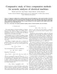
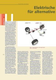
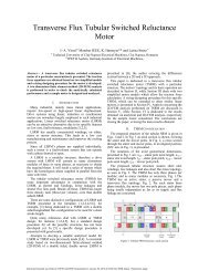
Fig. 2. HV-system modeled <strong>in</strong> PLECS<br />
For the Starter/Generator a PMSM-model <strong>in</strong> dq-axis is<br />
applied. The differential equations, <strong>of</strong> this system are<br />
di u<br />
⋅ ω<br />
d<br />
d<br />
Td + id<br />
= + ⋅Tq<br />
⋅iq<br />
dt R1<br />
di<br />
u<br />
ω ⋅ L<br />
q<br />
q<br />
hd<br />
T q ⋅ + iq<br />
= − ω ⋅Td<br />
⋅id<br />
− ⋅i′<br />
F 0<br />
dt R1<br />
R1<br />
J dω<br />
⋅ = p ⋅ 0<br />
p dt<br />
L<br />
where<br />
d Td<br />
= and T<br />
R<br />
[ i′<br />
F ⋅ Lhd<br />
− id<br />
⋅(<br />
Lq<br />
− Ld<br />
) ] ⋅iq<br />
− MW<br />
1<br />
q =<br />
Lq<br />
.<br />
R<br />
1<br />
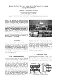
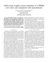
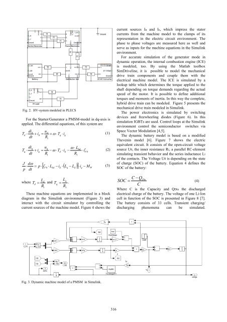
These mach<strong>in</strong>e equations are implemented <strong>in</strong> a block<br />
diagram <strong>in</strong> the Simul<strong>in</strong>k environment (Figure 3) and<br />
<strong>in</strong>teract with the circuit simulator by controll<strong>in</strong>g the<br />
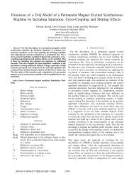
current sources <strong>of</strong> the mach<strong>in</strong>e model. Figure 4 shows the<br />
Fig. 3. Dynamic mach<strong>in</strong>e model <strong>of</strong> a PMSM <strong>in</strong> Simul<strong>in</strong>k.<br />
(1)<br />
(2)<br />
(3)<br />
316<br />
current sources Ia and Ic, which impress the stator<br />
currents from the mach<strong>in</strong>e model to the clamps <strong>of</strong> its<br />
representation <strong>in</strong> the electric circuit environment. The<br />
phase to phase voltages are measured here as well and<br />
serve as <strong>in</strong>puts for the mach<strong>in</strong>e equations <strong>in</strong> the Simul<strong>in</strong>k<br />
environment.<br />
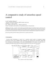
For accurate simulation <strong>of</strong> the generator mode <strong>in</strong><br />
dynamic operation, the <strong>in</strong>ternal combustion eng<strong>in</strong>e (ICE)<br />
is modeled, too. By us<strong>in</strong>g the Matlab toolbox<br />
SimDrivel<strong>in</strong>e, it is possible to model the mechanical<br />
drive tra<strong>in</strong> components and couple them with the<br />
electrical mach<strong>in</strong>e model. The ICE is simulated by a<br />
lookup table which determ<strong>in</strong>es the torque applied to the<br />
shaft depend<strong>in</strong>g on torque demands regard<strong>in</strong>g the actual<br />
speed <strong>of</strong> the motor. It is possible to def<strong>in</strong>e additional<br />
torques and moments <strong>of</strong> <strong>in</strong>ertia. In this way the complete,<br />
hybrid drive tra<strong>in</strong> can be modeled. Figure 5 presents the<br />
mechanical drive tra<strong>in</strong> modeled <strong>in</strong> Simul<strong>in</strong>k.<br />
The power electronics is simulated by switch<strong>in</strong>g<br />
devices and freewheel<strong>in</strong>g diodes (Figure 6). In this<br />
simulation IGBTs are used. Control loops at the Simul<strong>in</strong>k<br />
environment control the semiconductor switches via<br />
Space Vector Modulation [4,5].<br />
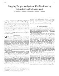
The dynamic battery model is based on a modified<br />
Theven<strong>in</strong> model [6]. Figure 7 shows the electric<br />
equivalent circuit. It consists <strong>of</strong> the open-circuit voltage<br />
source U0, the <strong>in</strong>ner resistance Ri, a parallel RC-element<br />
simulat<strong>in</strong>g transient behavior and the series <strong>in</strong>ductance Li<br />
<strong>of</strong> the contacts. The <strong>Voltage</strong> U0 is depend<strong>in</strong>g on the state<br />
<strong>of</strong> charge (SOC) <strong>of</strong> the battery. Equation 4 def<strong>in</strong>es the<br />
SOC <strong>of</strong> the battery:<br />
SOC<br />
C − Q<br />
C<br />
Dis = (4)<br />
Where C is the Capacity and QDis the discharged<br />
electrical charge <strong>of</strong> the battery. The voltage <strong>of</strong> one Li-Ion<br />
cell <strong>in</strong> function <strong>of</strong> the SOC is presented <strong>in</strong> Figure 8 [7].<br />
The battery consists <strong>of</strong> 33 cells. Transient charg<strong>in</strong>g/<br />
discharg<strong>in</strong>g phenomena can be simulated.