Simulation of a High Voltage System in a Hybrid Electrical Vehicle
Simulation of a High Voltage System in a Hybrid Electrical Vehicle
Simulation of a High Voltage System in a Hybrid Electrical Vehicle

Create successful ePaper yourself
Turn your PDF publications into a flip-book with our unique Google optimized e-Paper software.
Fig. 4. <strong>Voltage</strong> controlled current sources represent<strong>in</strong>g the<br />
PMSM <strong>in</strong> the circuit simulator.<br />
The load <strong>in</strong> the HV-system is an auxiliary drive, for<br />
<strong>in</strong>stance an electrical climate control unit. A PMSM<br />
mach<strong>in</strong>e model and a pulse-controlled <strong>in</strong>verter are<br />
implemented <strong>in</strong> this simulation. Similar model<strong>in</strong>g<br />
strategies for the electrical mach<strong>in</strong>e and the PE are<br />
utilized. Variable load cases can be simulated and<br />
studied.<br />
The DC-DC converter consists <strong>of</strong> a high frequency<br />
switch<strong>in</strong>g unit <strong>in</strong>clud<strong>in</strong>g a transformer to separate the<br />
two voltage levels [8,9,10]. Figure 9 shows its<br />
topology. A filter capacitor on each side reduces<br />
voltage ripples <strong>in</strong> the DC-l<strong>in</strong>k. The 12V load is be<strong>in</strong>g<br />
characterized by a load resistor Rload. S<strong>in</strong>ce the focus<br />
<strong>of</strong> this vehicle electrical system simulation<br />
concentrates on the HV-system, this simplification is<br />
appropriate.<br />
Power cables <strong>in</strong> the vehicle are simulated us<strong>in</strong>g πequivalent<br />
circuits with l<strong>in</strong>e resistance, leakage<br />
<strong>in</strong>ductance and capacitance to the car chassis (Figure<br />
10). Herewith model<strong>in</strong>g <strong>of</strong> transients <strong>in</strong> the cable<br />
harness dur<strong>in</strong>g dynamic operation is possible [11].<br />
The peripheral l<strong>in</strong>e represents the vehicle body at<br />
LV-DC m<strong>in</strong>us potential. Due to possible leakage<br />
currents to other electrical components <strong>of</strong> the vehicle,<br />
the car chassis is part <strong>of</strong> the model. Figure 11 shows<br />
the standardized structure <strong>of</strong> the <strong>in</strong>terconnection from a<br />
HV-component to vehicle chassis. Y-capacitors and<br />
<strong>in</strong>sulation resistances which can be reduced by<br />
switches are implemented.<br />
Event ports can be used to simulate deviations from<br />
regular operation, such as load dumps. They are<br />
standardized and control the switches which reduce<br />
component parameters or change the electric circuit.<br />
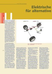
Fig. 5. Representation <strong>of</strong> the mechanical drive tra<strong>in</strong> modeled<br />
<strong>in</strong> Simul<strong>in</strong>k.<br />
317<br />
Fig. 6. Power electronics circuit <strong>in</strong> the HV-system.<br />
C. Control<br />
Control loops are implemented <strong>in</strong> the Simul<strong>in</strong>k level.<br />
Torque and speed control for the starter/generator <strong>in</strong><br />
motor operation or additional drives <strong>in</strong> the HV-<strong>System</strong><br />
is realized by us<strong>in</strong>g field oriented control strategies.<br />
Figure 12 shows the implemented speed control. A<br />
cascade control <strong>of</strong> current and speed is used to adjust<br />
the speed. Hereby a dynamic load for the vehicle<br />
electrical system is simulated.<br />
In generator operation the term<strong>in</strong>al voltage <strong>of</strong> the<br />
starter/generator (a PMSM) must be controlled by the<br />
power electronics, s<strong>in</strong>ce no excitation current can be<br />
modified. Here an active rectify<strong>in</strong>g method to control<br />
the charg<strong>in</strong>g current based on [12] and [13] is used.<br />
Provided that symmetric three phase s<strong>in</strong>usoidal<br />
currents<br />
⎡<br />
⎤<br />
⎡i<br />
⎤ ⎢ cosωt<br />
⎥<br />
R<br />
⎢ ⎥ ⎢ 2π<br />
⎥<br />
⎢<br />
i<br />
⎥<br />
= I ⋅ ⎢cos(<br />
ωt<br />
− ) ⎥<br />
(5)<br />
S<br />
⎢ ⎥ ⎢ 3 ⎥<br />
⎣iT<br />
⎦ ⎢ 2π<br />
cos( ωt<br />
+ ) ⎥<br />
⎢⎣<br />
3 ⎥⎦<br />
exists <strong>in</strong> the stator w<strong>in</strong>d<strong>in</strong>gs, all harmonics are<br />
neglected and no saturation occurs, two phase currents<br />
have to be measured and transformed to an orthogonal<br />
system to calculate the current amplitude. The<br />
follow<strong>in</strong>g transformation is used:<br />
⎡iA<br />
⎤ ⎡iR<br />
⎤<br />
⎢ ⎥ = T32<br />
⎢ ⎥<br />
⎣iB<br />
⎦ ⎣iS<br />
⎦<br />
⎡ 3 ⎤<br />
⎢ 0 ⎥<br />
T = ⎢ 2<br />
32<br />
⎥<br />
⎢ 1<br />
2⎥<br />
⎢⎣<br />
2 ⎥⎦<br />
(6)<br />
Fig. 7. Battery model based on Theven<strong>in</strong> equivalent<br />
circuit[6].