Camera Augmented Mobile C-arm - Chair for Computer Aided ...
Camera Augmented Mobile C-arm - Chair for Computer Aided ...
Camera Augmented Mobile C-arm - Chair for Computer Aided ...

You also want an ePaper? Increase the reach of your titles
YUMPU automatically turns print PDFs into web optimized ePapers that Google loves.
<strong>Camera</strong> <strong>Augmented</strong> <strong>Mobile</strong> C-<strong>arm</strong><br />
Student: Lejing Wang (2809335)<br />
Advisor: Jörg Traub<br />
Director: Prof. Nassir Navab<br />
Abstract:<br />
Traditional mobile C-<strong>arm</strong> that can take intra-operative X-ray images is popular in the<br />
operating room. But X-ray images that are displayed on the monitor are in the<br />
different space from the patients. For positioning and repositioning C-<strong>arm</strong>, it needs<br />
the skills, time and radiation. This paper presents <strong>Camera</strong> <strong>Augmented</strong> <strong>Mobile</strong> C-<strong>arm</strong><br />
(CAMC) system that can almost solve the problems mentioned be<strong>for</strong>e. The first<br />
section of the paper will introduce CAMC system from basic construction and<br />
principle. Then CAMC will be described from three different aspects corresponding<br />
to three different surgical applications in three more or less independent sections.<br />
After this, the Advanced CAMC system attaching 2 nd camera will be studied. In the<br />
end of this paper, it is the conclusion and the ideas <strong>for</strong> extending CAMC system in the<br />
near future are proposed.<br />
Introduction:<br />
The mobile C-<strong>arm</strong> is an essential everyday tool <strong>for</strong> most interventional procedures.<br />
Although the traditional mobile C-<strong>arm</strong> just can take 2D X-ray images, modern mobile<br />
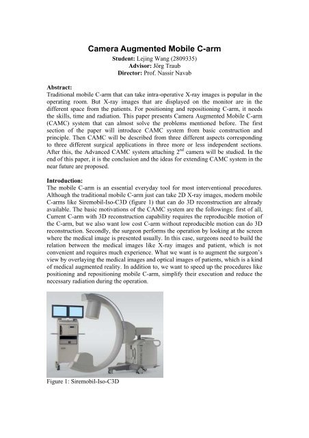
C-<strong>arm</strong>s like Siremobil-Iso-C3D (figure 1) that can do 3D reconstruction are already<br />
available. The basic motivations of the CAMC system are the followings: first of all,<br />
Current C-<strong>arm</strong> with 3D reconstruction capability requires the reproducible motion of<br />
the C-<strong>arm</strong>, but we also want low cost C-<strong>arm</strong> without reproducible motion can do 3D<br />
reconstruction. Secondly, the surgeon per<strong>for</strong>ms the operation by looking at the screen<br />
where the medical image is presented usually. In this case, surgeons need to build the<br />
relation between the medical images like X-ray images and patient, which is not<br />
convenient and requires much experience. What we want is to augment the surgeon’s<br />
view by overlaying the medical images and optical images of patients, which is a kind<br />
of medical augmented reality. In addition to, we want to speed up the procedures like<br />
positioning and repositioning mobile C-<strong>arm</strong>, simplify their execution and reduce the<br />
necessary radiation during the operation.<br />
Figure 1: Siremobil-Iso-C3D
<strong>Camera</strong> <strong>Augmented</strong> <strong>Mobile</strong> C-<strong>arm</strong> (CAMC) is constructed by attaching one camera<br />
and two mirrors to the gantry of C-<strong>arm</strong> (Figure 2) [1]. With this simple construction<br />
and the offline calibration <strong>for</strong> double mirrors, CAMC can really provide on-line<br />
recovery of the projection geometry used by 3D reconstruction <strong>for</strong> low cost C-<strong>arm</strong>,<br />
real time overlay of X-ray and optical image and speeding up positioning and<br />
repositioning mobile C-<strong>arm</strong>s with less radiation.<br />
Figure 2: The basic construction of CAMC<br />
Here, the basic idea and principle of CAMC will be shortly described. CAMC uses<br />
one camera to recover the motion of the C-<strong>arm</strong> and there<strong>for</strong>e the X-ray projection<br />
geometry during its rotational run around an object of interest [3]. The CCD camera<br />
attached to the C-<strong>arm</strong> is virtually at the same location as the x-ray source. This is done<br />
by a double mirror construction. A two step calibration routine has been done only<br />
once at the moment the camera is attached [1]. Visual servoing is used to do<br />
positioning and repositioning with pre-operative CT-data [4].<br />
Real-time recovery of the projection geometry using CAMC<br />
Real-time recovery of the projection geometry is useful in two points by CAMC: First<br />
point is 3D tomographic reconstruction in medical imaging. Moreover, it also can do<br />
overlay of 3D reconstruction and 2D optical images. The interesting observation that<br />
even though the motion parameters are better estimated using the external sensor, the<br />
projection geometry is more accurately estimated by the integrated optical camera [3].<br />
At the end of this section, you can directly see the better result from CAMC compared<br />
to using the external sensor.<br />
3D reconstruction<br />
Be<strong>for</strong>e the recovery of the projection geometry, the basic principle and steps <strong>for</strong> 3D<br />
reconstruction using X-ray C-<strong>arm</strong> is shortly described here. A sequence of images is<br />
captured during the C-<strong>arm</strong> rotation around the object of interest, and then all the 2D<br />
projection images are filtered, back-projected into the volume and combined to <strong>for</strong>m<br />
the volume data [2]. For each 2D image the precise projection geometry has to be<br />
determined <strong>for</strong> the 3D reconstruction process. The one way to recover X-ray<br />
projection geometry is the direct estimation, in which a calibration phantom with Xray<br />
opaque markers that is positioned such that it is visible in each frame has to be<br />
used. The biggest advantage of the direct estimation is that it will get the most<br />
accurate estimation of the projection geometry <strong>for</strong> each X-ray frame. The projection<br />
matrices are obtained with this method as gold standard– all other methods are<br />
compared to it [2]. However, marker points visible in the sequence of X-ray images<br />
that overlay the object (patient’s anatomy) will influence the result of the 3D
econstruction in the medical imaging application. But this problem can be solved in<br />
an offline procedure if the motion of the C-<strong>arm</strong> is reproducible.<br />
The projection geometry has to be determined online if the motion of the C-<strong>arm</strong> is not<br />
reproducible. The followings define the framework <strong>for</strong> online recovery of X-ray<br />
projection geometry. First, we briefly introduce the X-ray projection geometry.<br />
The X-ray projection geometry is represented by P a 3*4 homogeneous matrix of<br />
projection [3].<br />
U = P X, (1)<br />
where U = [u; v; 1] T and X = [x; y; z; 1] T are the homogeneous coordinates of an<br />
image pixel (2D) and corresponding 3D voxel of the world coordinate system.<br />
P = [AR AT] (2)<br />
where R, and T are extrinsic parameters. A is the intrinsic parameters.<br />
In our case, we will model the X-ray imaging system by a pinhole camera model. The<br />
intrinsic parameters of X-ray source will not be as constant as it can be assumed <strong>for</strong><br />
standard CCD camera. It is interesting to note that the intrinsic parameters of a<br />
moving X-ray system depend in general on its extrinsic parameters [3].<br />
For fixing the intrinsic parameters of X-ray source, we propose using virtual detector<br />
plane. The intrinsic parameters of CCD camera only depend on the manufacturing of<br />
the camera and the relation between image plane, focal point, and optical axis stay<br />
fixed. In the case of C-<strong>arm</strong> X-ray system, focal point (X-ray source) and image plane<br />
(X-ray detector) are far apart from each other, and the weights of both X-ray source<br />
and detector the C-<strong>arm</strong> will cause minor torsion during the motion. Besides, the<br />
optical axis (normal dropping from X-ray source on the detector plane) depends on<br />
the orientation of the detector plane [3].<br />
Figure 3: Pinhole camera model: Differences between CCD camera (top) and X-ray<br />
imaging system (bottom)<br />
We found a solution to solve this problem by introducing the concept of a virtual<br />
detector plane [3]. We attach a number of makers to the X-ray source, and then Force
the markers projected to the image at pre-defined positions by image trans<strong>for</strong>mation<br />
3*3 matrix H. The virtual detector plane is defined <strong>for</strong> all images by image<br />
trans<strong>for</strong>mation such that these markers are projected to pre-defined positions.<br />
The image trans<strong>for</strong>mation is described by a 2D-2D planar trans<strong>for</strong>mation H.<br />
Pi VD = A VD · Ei = (Hi · Ai ) · Ei = Hi · Pi (3)<br />
Pi VD is the projection matrix with the fixed intrinsic parameters <strong>for</strong> i-th frame. The<br />
fixed intrinsic parameters are represented by A VD . The equation 3 gives us the way<br />
how to use the original projection matrix in order to get a projection matrix with the<br />
changed intrinsic geometry.<br />
Another necessary component <strong>for</strong> recovering the projection geometry is the reference<br />
frame. A pair of images (X-ray and optical) is taken <strong>for</strong> an arbitrary frame. The<br />
projection geometry is determined simultaneously <strong>for</strong> both X-ray P X ref) and the<br />
camera (P c ref) used as references.<br />
The last thing is needed to do <strong>for</strong> recovering the projection geometry is the motion<br />
estimation. An optical marker system, not visible in the X-ray image, is used to<br />
determine the projection geometry of the CCD camera <strong>for</strong> each frame. The motion of<br />
X-ray source between current and reference frame is computed from the estimated<br />
CCD camera projection matrices.<br />
P ^X i =P X ref · M X i with P c i =P c ref · M c i (4)<br />
The one thing you should notice is that P ^X i projects 3D voxels onto the virtual<br />
detector plane. We need to trans<strong>for</strong>m P ^X i to the original projection matrix Pi by using<br />
the equation 3.<br />
Experimental Results<br />
The set of projection matrices that has been computed <strong>for</strong> each method is used to<br />
reconstruct a test phantom. It consists of two cylindrical objects in an acrylic cover.<br />
Attached to it is a ring made from titanic alloy also in an acrylic cover.
Figure 4: Experimental results of 3D reconstruction (from top to bottom): CAMC,<br />
CHOU, DANI, gold standard and the test phantom used in the experiment<br />
The results are shown in figures 4. The 3D reconstructed volumes are visualized as<br />
orthogonal Maximum Intensity Projections (MIP). Both the gold standard of using<br />
direct estimation and the CCD camera approach lead to better reconstruction quality<br />
than the external tracking system method [3].<br />
3D-2D Overlay using CAMC<br />
The projection geometry of X-ray recovered by CAMC can be used to project the 3D<br />
reconstruction data from CAMC to 2D images (simulated X-ray images) without<br />
taking the actual X-ray image again. The surgeon can move C-<strong>arm</strong> freely and observe<br />
the simulated X-ray images without X-ray exposure from different viewpoints if the<br />
patient is immobilized.<br />
This process also can be used in order to visualize the 3D reconstruction combined<br />
with the camera images. Due to using optical imaging parameters as 3D volume<br />
rendering parameters, then C-<strong>arm</strong> geometry and the result of 3D reconstruction from<br />
CAMC are defined in the same coordinate system as the optical camera, which makes<br />
the overlay the 3D reconstruction and camera images possible.<br />
Figure 5: The superimposition of the reconstructed volume on top of optical images<br />
Figure5 shows the experimental results of the overlaying the 3D reconstruction and<br />
camera images of using pig’s knuckle. The left one is the camera optical image, the<br />
middle one is the X-ray image and right one is the overlay image.<br />
Real time overlay of X-ray and optical image using CAMC
Clinician usually does operation by looking at the screen where the X-ray images are<br />
displayed. In this case, the medical (X-ray) images and patients are in different space,<br />
which is not convenient. We want to put the X-ray images and patients into the same<br />
space. One way is to overlay medical images and patient optical images. In the<br />
previous section 2D-3D overlay, we have already got the overlay of the 3D<br />
reconstruction and patient camera images. But the problem is that 2D-3D overlay<br />
need 3D reconstruction first, which means inevitable much X-ray exposure. What we<br />
want here is merging both X-ray and optical images without pre-computed 3D<br />
reconstruction.<br />
Without pre-computed 3D reconstruction, merging both X-ray and optical images<br />
requires they are taken from same viewpoint. The X-ray source and the camera center<br />
should be at the same place, which is not physically possible. However, we propose to<br />
use two mirrors to bend the principle axis of the CCD camera in such a way that both<br />
principal axes are aligned like Figure6 [1].<br />
Figure 6: Conceptual design of the double mirrors<br />
With the double mirrors construction, totally blending X-ray and optical images using<br />
CAMC with double mirrors requires 1) Precise alignment of the principle axes of both<br />
X-ray and optical imaging systems, 2) 2D-2D co-registration <strong>for</strong> correcting the<br />
difference in the intrinsic parameters.<br />
We can use a single offline calibration procedure to meet the both requirements, and<br />
the calibration procedure includes 5 steps [1].<br />
1. Position 4 or more markers on the X-ray detector plane and one or more extra<br />
markers that are further from the plane<br />
2. Take one X-ray image<br />
3. Compute the image plane trans<strong>for</strong>mation based on the in-plane corresponding<br />
markers (Figure7)
H<br />
I I<br />
Figure 7: Calibration, left one is the optical image and the right is the X-ray image<br />
4. Move camera until the out of plane markers are superimposed, which aligns the<br />
principle axes (Figure 8)<br />
camera<br />
XX-Ray<br />
Figure 8: Calibration, superimposing out of plane markers<br />
5. Fix the camera and record the final estimated planar trans<strong>for</strong>mation<br />
With double mirrors, this system can continue blend the video images with the fixed<br />
X-ray image. If the region of interest is immobilized, the clinician can work under the<br />
guidance of this augmented video and no registration of the patient was required. The<br />
clinician also can control the blending coefficient, between 0 (only X-ray image) and<br />
1(only video image)<br />
Experimental Results<br />
In the experiment, the set of metallic objects are used. The objects are placed on the<br />
table such that they occlude each other (Figure9)<br />
Figure 9: The set of metallic objects<br />
The Figure 10 shows us the results. The occluded parts can be seen in the X-ray<br />
image and the combined image.
Figure 10: The left is the original video, the center is the overlay and the right is the<br />
pure X-ray image<br />
Visual Servoing of CAMC<br />
Visual servoing are mostly used in robotic systems <strong>for</strong> control of robot manipulators<br />
that is based on visual perception. Visual servoing involves the use of one or more<br />
cameras and a computer vision system to control the position of the robot's endeffector<br />
relative to the workpiece as required by the task. Here, it will control the C<strong>arm</strong><br />
using the visual in<strong>for</strong>mation taken from the on-board camera.<br />
The problem of positioning mobile C-<strong>arm</strong>s, e.g. <strong>for</strong> down the beam techniques, as<br />
well as repositioning during surgical procedures currently requires time, skill and<br />
additional radiation. The <strong>Camera</strong>-<strong>Augmented</strong> <strong>Mobile</strong> C-<strong>arm</strong> (CAMC) with visual<br />
servoing is able to speed up the procedure, simplify its execution and reduce the<br />
necessary radiation. The advantage here is the use of visual servoing with no radiation<br />
<strong>for</strong> positioning a mobile C-<strong>arm</strong> to obtain target images defined <strong>for</strong> the X-ray imaging<br />
[4]. We propose two visual servoing algorithms providing elegant solutions <strong>for</strong><br />
per<strong>for</strong>ming down the beam techniques and repositioning with no additional radiation<br />
<strong>for</strong> surgeon as well as <strong>for</strong> the patient. In the rest of this section, the basic principle of<br />
using visual servoing and working steps will be described.<br />
For Down-the-Beam positioning of the C-<strong>arm</strong>, we use a pre-operative CT to define<br />
the Down-the-Beam axis. Intra-operatively we estimate the current pose of the C-<strong>arm</strong><br />
with regards to the CT data (figure 11). Position-based visual servoing is used to<br />
move the C-<strong>arm</strong> towards the desired position. When we are close to the optimal<br />
position, we generate the virtual target images and then witch to image-based visual<br />
servoing [4].<br />
Figure 11: Down-the-Beam C-<strong>arm</strong> positioning<br />
The repositioning task is done by (optical) image-based visual servoing. A target<br />
image from the current C-<strong>arm</strong> position is taken. When the C-<strong>arm</strong> is repositioned, the
current positions of the fiducials are compared to the target positions and joint<br />
increments of the C-<strong>arm</strong> are computed (figure 12)[4].<br />
Figure 12: Intra-operative repositioning<br />
Experimental Results of C-<strong>arm</strong> Repositioning<br />
The standard radiographic examination of the ankle <strong>for</strong> fracture detection will be<br />
studied by using cadaver. Intraoperatively the precise mortise view is mandatory to<br />
proof the correct reposition of the ankle [4].<br />
Figure 13: ankle joint repositioning; 1: reference video; 2: reference X-ray; 3: blended<br />
reference images; 4-8: images acquired during movement from start to reference<br />
position of C-<strong>arm</strong>.<br />
Advanced system: Integrating 2nd camera to CAMC<br />
<strong>Camera</strong> <strong>Augmented</strong> <strong>Mobile</strong> C-<strong>arm</strong> is really useful <strong>for</strong> many interventional procedures.<br />
However, this CAMC, in which no depth control is possible, just provides an accurate<br />
positioning and guidance of instruments in 2D by doing real time overlay of X-ray<br />
and optical images. This makes CAMC limited to applications where depth did not<br />
matter, like in im-nail locking. Based on this CAMC, the advanced system is<br />
developed by integrating a 2nd camera (Figure 14). The second camera is attached<br />
orthogonal to the gantry such that its view is aligned with the X-ray image after a 90<br />
degrees orbital rotation of the C-<strong>arm</strong>. This advanced system is also capable of depth<br />
control during trauma surgery and orthopedic procedures using only one additional Xray<br />
image and a second video camera that is rigidly attached to the C-<strong>arm</strong> [5].
Figure 14: The C-<strong>arm</strong> with two attached optical cameras.<br />
CAMC uses second camera to track the instrument attaching optical markers. Using<br />
invariance of cross ratio under projective trans<strong>for</strong>mation, we estimate the position of<br />
the tip in the image. After one time calibration of the newly attached second video<br />
camera we are able to show the instrument tip in the orthogonal X-ray view [5].<br />
Notation Since we have images at different positions of the C-<strong>arm</strong> superscript 0<br />
denote cameras and images at a 0 degree orbital rotation and superscript 90 denote<br />
cameras and images acquired by the C-<strong>arm</strong> after an orbital rotation around 90 degree.<br />
Furthermore subscript x is used <strong>for</strong> X-ray, g <strong>for</strong> gantry mounted, and o <strong>for</strong> the<br />
orthogonal mounted cameras.<br />
To get best results <strong>for</strong> the depth navigation, we have to ensure that after an orbital<br />
rotation the optical center and axis of the X-ray gantry and the orthogonal camera are<br />
aligned. The gantry mounted (1st) camera and X-ray source have already been<br />
calibrated as described be<strong>for</strong>e. For aligning optical center and axis of X-ray to<br />
orthogonal mounted camera, it can be done by physically aligning the gantry mounted<br />
and orthogonal mounted camera after rotation [5]. After aligning optical center and<br />
axis, 2D planar trans<strong>for</strong>mation remains to be computed <strong>for</strong> correcting intrinsic<br />
parameters. Hgx maps the X-ray image I 90 x to the gantry mounted image I 90 g and Hog<br />
maps the image of the gantry mounted camera I 90 g to the image of the orthogonal<br />
mounted camera I 0 o. Finally, Hgx · Hog maps the X-ray image I 90 x to the orthogonal<br />
mounted camera image I 0 o.<br />
Experimental Results<br />
With second camera, we still need to track the instruments. In the experiment, the<br />
instrument is extended by three markers collinear arranged on the instrument axis. We<br />
use retro-reflective circular markers that are illuminated by an additional light source<br />
attached to the orthogonal camera (Figure 15 middle). According to these illuminated<br />
markers and the invariance of cross ratio, the tip of the instrument can be tracked.<br />
Figure 15 show us the results from the cadaver study.
Figure 15: First camera <strong>for</strong> lateral positioning (left), Second camera <strong>for</strong> depth tracking<br />
(middle) and Superimposition of depth tracking onto the X-ray image (right)<br />
Conclusion<br />
<strong>Camera</strong> <strong>Augmented</strong> <strong>Mobile</strong> C-<strong>arm</strong> not only provides robust 2D AR-visualization, but<br />
also 3D AR-visualization with 2nd camera. First cadaver experiment demonstrated<br />
that the advanced system can be easily integrated into the clinical workflow while<br />
reducing the radiation dose compared to other methods [5]. By using visual servoing,<br />
the number of positioning steps is comparable to clinical routine but without any<br />
radiation exposure. However X-ray images can be obtained at any time to check the<br />
reached position or to check patient movement [4].<br />
Future possible extension of CAMC<br />
CAMC can overlay the medical images and patient images in real time, which<br />
augments the surgeon‘s view and benefits many interventional procedures, but these<br />
images are displayed by the monitor, so surgeons need to check monitor during<br />
operation. What we want in the future is to let surgeons can concentrate on the patient<br />
without checking monitor during operation.<br />
References:<br />
1. Navab, N., Mitschke, M., Bani-Hashemi, A.: Merging visible and invisible:<br />
Two camera-augmented mobile C-<strong>arm</strong> (CAMC) applications. In: Proc. IEEE<br />
International Workshop on <strong>Augmented</strong> Reality, San Francisco, CA, USA<br />
(1999) 134–141<br />
2. N. Navab, A. Bani-Hashemi, M. S. Nadar, K. Wiesent, P. Durlak, T. Brunner,<br />
K. Barth, R. Graumann. 3D reconstruction from projection matrices in a C<strong>arm</strong><br />
based 3D-angiography system, MICCAI, 1998.<br />
3. M. Mitschkea, N. Navab: Recovering Projection Geometry: How a cheap<br />
camera can outper<strong>for</strong>m an expensive stereo system, IEEE, 2000.<br />
4. N. Navab, S. Wiesner, S. Benhimane, E. Euler, S.M. Heining; Visual Servoing<br />
<strong>for</strong> Intraoperative Positioning and Repositioning of <strong>Mobile</strong> C-<strong>arm</strong>s; Proc. Of<br />
MICCAI 2006<br />
5. J. Traub, T.H. Heibel, P. Dressel, S.M. Heining,R. Graumann, N. Navab; A<br />
Multi-View Opto-Xray Imaging System Development and First Application in<br />
Trauma Surgery; Proc. Of MICCAI 2007