SAILOR SP3515 VHF - Busse Yachtshop
SAILOR SP3515 VHF - Busse Yachtshop
SAILOR SP3515 VHF - Busse Yachtshop

Create successful ePaper yourself
Turn your PDF publications into a flip-book with our unique Google optimized e-Paper software.
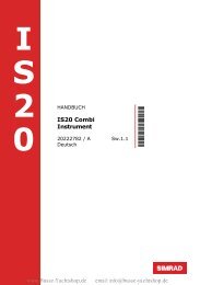
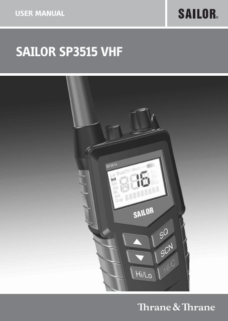
USER MANUAL<br />
<strong>SAILOR</strong> <strong>SP3515</strong> <strong>VHF</strong>
Emergency procedure<br />
• Turn the knob at the top of the radio clockwise. The display lights up<br />
showing the last used channel and the battery level.<br />
• Select channel 16 (Distress or Safety), press the 16/C key.<br />
• Press the PTT and say:<br />
— “MAYDAY, MAYDAY, MAYDAY”,<br />
— “This is”..... ships name repeated three times<br />
—<br />
— “MAYDAY”<br />
— “This is”..... ships name and call sign,<br />
— The ship’s position in latitude and longitude or other reference<br />
to a known geographical location,<br />
— The nature of distress and assistance wanted,<br />
— Any other information which might facilitate the rescue.<br />
— “OVER”<br />
• Release PTT and listen for answer.<br />
0709
<strong>SP3515</strong> <strong>VHF</strong><br />
Document number: TT 98-124293-E<br />
Release date: October, 2007<br />
Copyright: © 2007 Thrane & Thrane A/S. All rights reserved.<br />
Trademark Acknowledgements<br />
• <strong>SAILOR</strong> is a registered trademark of Thrane & Thrane A/S.<br />
• Other product and company names mentioned in this manual may be<br />
trademarks or trade names of their respective owners.<br />
Warranty limitation<br />
IMPORTANT - The radio is a sealed waterproof unit. To create and maintain its<br />
waterproof integrity it was assembled in a controlled environment using special<br />
equipment. The radio is not a user maintainable unit, and under no circumstances<br />
should the unit be opened except by authorized personnel. Unauthorized opening<br />
of the unit will invalidate the warranty.<br />
Disclaimer<br />
Any responsibility or liability for loss or damage in connection with the use of this<br />
product and the accompanying documentation is disclaimed by Thrane & Thrane.<br />
The information in this manual is provided for information purposes only, is<br />
subject to change without notice, may contain errors or inaccuracies, and<br />
represents no commitment whatsoever by Thrane & Thrane. This agreement is<br />
governed by the laws of Denmark.<br />
Manuals issued by Thrane & Thrane are periodically revised and updated. Anyone<br />
relying on this information should satisfy himself/herself as to the most current<br />
version. Providers with access to Thrane & Thrane's Extranet may obtain current<br />
copies of manuals at: http://extranet.thrane.com<br />
Thrane & Thrane is not responsible for the content or accuracy of any translations<br />
or reproductions, in whole or in part, of this manual from any other source.<br />
0740<br />
i
ii<br />
Precautions<br />
Avoid water and salt in the I/O connector and keep it<br />
clean frequently.<br />
Only use original Thrane & Thrane battery packs. Make<br />
sure they are clean and dry before attaching the<br />
transceiver. Be careful not to damage any gaskets.<br />
Only use the original Thrane & Thrane charger for the<br />
rechargeable battery.<br />
Be very careful when handling the Lithium batteries.<br />
With correct use they are safe but any misuse might<br />
cause dangerous situations.<br />
Never short circuit the battery terminals, never expose<br />
the transceiver and the batteries to extreme temperature<br />
or fire and never use any kind of violence.<br />
Avoid close contact between the antenna and parts of<br />
the human body. The top of the antenna must never be<br />
closer than 5 cm to the body when transmitting.<br />
Do not submerge the transceiver more than 1 m for 30<br />
minutes.<br />
Keep the transceiver at least 0.3 m away from the<br />
magnetic compass.<br />
0709
Training information<br />
<strong>SAILOR</strong> <strong>SP3515</strong> <strong>VHF</strong> is designed for "occupational use only". It must be operated by<br />
licensed personnel only.<br />
The <strong>SP3515</strong> complies with the FCC RF exposure limits for "Occupational Use Only".<br />
• FCC OET Bulletin 65 Supplement C, evaluating compliance with FCC guidelines<br />
for human exposure to radio frequency electromagnetic fields.<br />
• American National Standards Institute (C95.1) IEEE standard for safety levels<br />
with respect to human exposure to radio frequency electromagnetic fields,<br />
3 kHz to 300 GHz.<br />
• American National Standards Institute (C95.3) IEEE recommended practice for<br />
the measurement of potentially hazardous electromagnetic fields - RF and<br />
microwaves.<br />
Correct use<br />
For best performance, hold the radio vertically and 10 cm away from the head<br />
when talking into the microphone.<br />
0703<br />
Warning! Your Thrane & Thrane <strong>VHF</strong> radio generates<br />
electromagnetic RF (radio frequency) energy when<br />
transmitting. To ensure that you are not exposed to excessive<br />
amounts of energy and thus to avoid health hazards from<br />
excessive exposure to RF energy, all persons must be at least 5<br />
cm away from the antenna when the radio is transmitting.<br />
iii
iv 0641
Chapter 1 Introduction<br />
Chapter 2 Operation<br />
Contents<br />
Your <strong>VHF</strong> .............................................................................1<br />
Performance .......................................................................2<br />
Channels ............................................................................2<br />
Controls ..............................................................................5<br />
Keys and buttons ................................................................5<br />
The display .........................................................................7<br />
Using the <strong>VHF</strong> .....................................................................8<br />
Basic functions ...................................................................8<br />
Other functions .................................................................. 11<br />
Chapter 3 Batteries<br />
Battery level indication ......................................................15<br />
Removing and inserting the battery pack ...........................15<br />
The battery charger ...........................................................16<br />
Installing the charger ........................................................16<br />
Recharging the battery ......................................................17<br />
Chapter 4 Configuring the radio<br />
Configuration mode ...........................................................19<br />
Entering and using configuration mode ............................19<br />
List of configuration settings .............................................20<br />
0703<br />
v
Chapter 5 Equipment and accessories<br />
vi<br />
External equipment .......................................................... 27<br />
List of equipment .............................................................. 27<br />
Connecting external equipment ........................................ 27<br />
Impact on radio operation ................................................ 28<br />
Accessorie connector ........................................................ 28<br />
Accessories ...................................................................... 29<br />
List of accessories ............................................................. 29<br />
Attaching and removing the belt clip .................................31<br />
Attaching the lanyard ........................................................31<br />
Chapter 6 Troubleshooting<br />
Displaying errors .............................................................. 33<br />
App. A Technical specifications<br />
Technical data <strong>SP3515</strong> ...................................................... 35<br />
General ............................................................................ 35<br />
Transmitter ....................................................................... 36<br />
Receiver ........................................................................... 36<br />
Battery life guidelines ...................................................... 38<br />
Dimensional drawing, transceiver .................................... 39<br />
Dimensional drawing, chargers ....................................... 40<br />
Declaration of Conformity ..................................................41<br />
App. B Attention<br />
Goretex Membran ............................................................ 43<br />
0740
Introduction<br />
Your <strong>VHF</strong><br />
The <strong>SP3515</strong> <strong>VHF</strong> is designed for flexibility in daily<br />
use. It connects easily to external equipment like<br />
headsets and fist mikes, making the <strong>SP3515</strong><br />
suitable for any noisy environment.<br />
Main features:<br />
Unique man machine interface, an excellent<br />
grip even with gloves, and large tactile<br />
buttons.<br />
Display with red adjustable backlight which<br />
makes the display visible even at night.<br />
Built-in “sleep” function, minimizing power<br />
consumption and improving battery lifetime.<br />
Selectable 12.5 kHz narrow band or 25 kHz<br />
wide band operation.<br />
Scrambling function for privacy calls.<br />
CTCSS function for selective opening of<br />
Squelch.<br />
A lanyard and belt clip included.<br />
A huge accessory program comes with the<br />
<strong>SAILOR</strong> SP3500 series.<br />
Please find the nearest <strong>SAILOR</strong> distributor on<br />
www.thrane.com.<br />
0643<br />
Chapter 1<br />
1
Introduction<br />
Performance<br />
For best performance of the transceiver keep the following in mind:<br />
• Keep clear of metal environment.<br />
• Hold the transceiver vertically and 10 cm from lips and push the PTT<br />
when transmitting.<br />
• In receive mode carry the transceiver vertically with belt clips.<br />
• To preserve battery power, adjust squelch to close the loudspeaker<br />
when there is no signal.<br />
• If you are in a lifeboat keep the antenna as high as possible.<br />
Channels<br />
This radio operates default with the following channel designators (see<br />
also ITU-R M.1084-4), depending on the configuration (see the notes on<br />
the next pages):<br />
2<br />
1 9 17 25 60 68 77 85 US W-ch. CA W-ch.<br />
2 10 18 26 61 69 78 86 W1 W8 W1<br />
3 11 19 27 62 71 79 87 W2 W9 W2<br />
4 12 20 28 63 72 80 88 W3 W10 W3<br />
5 13 21 64 73 81 W4<br />
6 14 22 65 74 82 W5<br />
7 15 23 66 75 83 W6<br />
8 16 24 67 76 84 W7<br />
0740
Channel modes<br />
Introduction<br />
The notes in the following sections list the channel restrictions that apply<br />
for each channel mode.<br />
For information on how to select a channel mode, see Entering and using<br />
configuration mode on page 19 and CHAN on page 20.<br />
National frequency regulations shall always be respected and might<br />
restrict operation for this type of equipment.<br />
International channels<br />
Note:<br />
Tx power is limited to 1 W on channels 75 and 76.<br />
US channels<br />
Notes:<br />
• Tx power is limited to 1 W on channels 13, 67 and 77.<br />
• The channels 2, 4, 60, 61, 62, 75 and 76 cannot be selected.<br />
• The Weather channels (US W-ch. in the channel table) can only be<br />
used in Rx direction.<br />
• Channel 15 can only be used in Rx direction. Tx direction is blocked.<br />
• The channels 1, 3, 5, 7, 18, 19, 21, 22, 23, 63, 64, 65, 66, 78, 79, 80, 81,<br />
82 and 83 may only be used as simplex channels (and is marked A).<br />
Channel 20 may be used as semi-duplex and simplex as 20A.<br />
0740<br />
3
Introduction<br />
Canadian channels<br />
Notes:<br />
• Tx power is limited to 1 W on channels 15, 17, 20, 65, 66 and 77.<br />
• The channels 19, 22, 63, 75, 76 and 81 cannot be selected.<br />
• The Weather channels (CA W-ch. in the channel table) can only be<br />
used in Rx direction.<br />
• The channel 21 can only be used in Rx direction, marked 21B. Tx<br />
direction is blocked.<br />
• The channels 4, 5, 7, 18, 19, 21, 22, 61, 62, 64, 65, 66, 78, 79, 80, 81 and<br />
82 may only be used as simplex channels (and marked A). Channel 83<br />
may be used as semi-duplex and simplex as 83A.<br />
Inland Waters (BI) channels<br />
Notes:<br />
• Tx power is limited to 1 W on channels 15 and 17.<br />
• ATIS function is enabled on all channels.<br />
• Dual watch and Scanning modes are disabled.<br />
ATIS is automatically transmitted after each transmission in Inland<br />
Waters. See ATIS on page 22 for information on how to program the call<br />
sign.<br />
4<br />
0740
Operation<br />
Controls<br />
Keys and buttons<br />
1. On/off/volume<br />
2. Light/Lock<br />
3. Push To Talk (PTT)<br />
4. Up key<br />
5. Down key<br />
6. Hi/Lo output power<br />
7. Squelch<br />
8. Scan<br />
9. Priority channel (16)/<br />
Call channel<br />
10. Loudspeaker/microphone<br />
0740<br />
2<br />
3<br />
4<br />
5<br />
6<br />
Operation<br />
1<br />
7<br />
8<br />
9<br />
10<br />
5
Operation<br />
Key presses<br />
Pressing and holding certain keys gives access to additional functions,<br />
shown in the table below.<br />
6<br />
Key<br />
Short press<br />
(1 beep)<br />
Show next available<br />
item in the list (up or<br />
down).<br />
Default: Channel<br />
selection<br />
Activate Squelch<br />
control (Adjust with<br />
up/down arrows).<br />
1 press: Activate/<br />
terminate Dual/Triple<br />
watch.<br />
2 presses: Activate<br />
memory scan.<br />
Toggle between high<br />
and low transmitter<br />
power.<br />
Long press<br />
(2 beeps)<br />
Run through available<br />
items, or<br />
select tagged channels<br />
A () or B ().<br />
Monitor function. Open<br />
Squelch completely.<br />
Set period of time in<br />
configuration mode.<br />
Add/Delete channel<br />
from memory scan.<br />
Select channel 16. Select programmed<br />
Call channel.<br />
Extra long<br />
press<br />
(3 beeps)<br />
Run through<br />
available<br />
items if an A<br />
or B channel<br />
is tagged<br />
Program Call<br />
channel.<br />
0703
The display<br />
The display holds various fields of information, explained below.<br />
3<br />
2<br />
1<br />
4 5 6<br />
Operation<br />
1. Current working channel.<br />
2. Current channel mode.<br />
3. “Lo”: Reduced transmitter power.<br />
Full transmitter power is not shown in display.<br />
4. Dual/Triple watch activated.<br />
5. Current working channel is marked for scanning.<br />
6. Keypad is locked.<br />
7. Battery level indicator.<br />
8. Transmitting (Tx) /Receiving (Rx).<br />
9. Accessory is connected.<br />
10. Service line for various purposes. In this example the volume level.<br />
11. Semi-duplex channel.<br />
0740<br />
11<br />
10<br />
7<br />
8<br />
9<br />
7
Operation<br />
Using the <strong>VHF</strong><br />
Basic functions<br />
Switching the radio on and off<br />
• To switch the radio on, turn the knob at the top<br />
of the radio clockwise.<br />
The display lights up showing the last used<br />
channel and the battery level.<br />
• To switch the radio off, Turn the knob back<br />
counter-clockwise until it clicks.<br />
Selecting the working channel<br />
• To select channel 16 (Distress or Safety), press the 16/C key.<br />
• To select the Call channel, use a long press on 16/C.<br />
• To select among all available channels, press or on the keypad.<br />
For fast selection, press and hold or .<br />
The display shows the currently selected channel. The bottom left corner<br />
of the display shows “Dup” if the channel is a semi-duplex channel.<br />
8<br />
Note Before using the radio, mount the antenna at the top of the<br />
radio. The antenna is delivered with the radio.<br />
Note Long press on or can also be used to select preferred<br />
channels. For information on how to program preferred<br />
channels, see Configuring the radio on page 19.<br />
0740
Activating a call<br />
To activate a call to the selected channel, press and<br />
hold the PTT button on the side of the radio.<br />
The radio transmits as long as the PTT button is<br />
pressed. A small Tx sign next to the channel number<br />
indicates when the radio is in transmit mode.<br />
Adjusting the volume<br />
Operation<br />
• To increase the volume, turn the on/off knob at the top of the radio<br />
clockwise.<br />
• To decrease the volume, turn the knob counter-clockwise.<br />
The display shows the level of the volume, e.g. “VOL 5”, while it is<br />
adjusted.<br />
Using Squelch control<br />
• To activate Squelch control, press the SQ key.<br />
• To set the Squelch level, press (closing) or (opening). The<br />
display shows the Squelch level while it is adjusted, e.g. “SQ 5”.<br />
Adjusting the display backlight<br />
• To turn on the backlight, press the<br />
Light/Lock button on the side of the radio.<br />
• To adjust the backlight level, press or <br />
within 3 seconds after turning on the light.<br />
The display shows the level while it is<br />
adjusted, e.g. “DIM MED”.<br />
0703<br />
9
Operation<br />
Using Dual/Triple watch<br />
• To activate Dual/Triple watch, press the SCN key.<br />
The display shows “Dual” or “Tri” at the top and “16” at the<br />
bottom right. The radio toggles between the selected channel and<br />
channel 16 in Dual watch. In Triple watch, the radio shifts between<br />
channel 16, the call channel and the selected channel.<br />
To select whether the SCN key should activate Dual or Triple watch,<br />
refer to Configuring the radio on page 19.<br />
• To terminate Dual watch, press SCN again.<br />
Scanning channels<br />
• To activate scanning memory, press 2 times SCN within 2 seconds.<br />
During scanning, the display shows “SC” in the channel field. The<br />
radio toggles between channel 16 and each of the channels marked<br />
for scanning.<br />
• To terminate scanning, press SCN once.<br />
Changing the transmitter power<br />
To change the transmitter power, press the Hi/Lo key. The display shows<br />
“Lo” when power is set to low. Otherwise maximum power is used.<br />
Locking the keypad<br />
• To lock the keypad, press and hold the Light/Lock button. The display<br />
shows a key symbol when the keypad is locked.<br />
• To unlock the keypad, press and hold the Light/Lock button again.<br />
10<br />
0740
Other functions<br />
Programming the Call channel<br />
To program the Call channel, do as follows:<br />
Operation<br />
1. Press and hold 16/C until the current Call channel number is flashing.<br />
2. Select the channel with or .<br />
3. Press 16/C to confirm within 3 seconds.<br />
Programming the scanning memory<br />
To add a channel to the scanning memory, select the channel and then<br />
press and hold the SCN key until the display shows MEM at the top.<br />
To remove a channel from the scanning memory, select the channel and<br />
then press and hold the SCN key until the MEM sign disappears from the<br />
display.<br />
Low power operation<br />
The radio can be operated in low power mode. In this mode battery life<br />
time is dramatically increased. Up to the first second of a received call<br />
might be lost if this mode is selected. Refer to SLEEP on page 21.<br />
Continuous Tone Coded Squelch System<br />
On channels where it is allowed, you can set up selective squelch<br />
opening by sub-tone detection (CTCSS), using the configuration mode<br />
(see CTCSS on page 24). Please note that if the radio is operating with<br />
CTCSS on a channel, it is impossible to receive a normal signal on that<br />
channel. For this reason, be very careful not to use CTCSS programmed<br />
channels in emergency situations. Channels programmed with CTCSS will<br />
0740<br />
11
Operation<br />
have a clear identification in the service field, e.g. "CTCSS 22", while<br />
selected. Not all channels are allowed for CTCSS use.<br />
In maritime channel modes CTCSS is automatically disabled when<br />
• Product is turned off<br />
• A new channel is selected<br />
For private channels and ALT channel mode, the feature will remain until<br />
manually removed.<br />
Scrambler<br />
On channels where it is allowed, you can set up voice scrambling, using<br />
configuration mode (see SCRM on page 25).<br />
Please note that if the radio is operating with scrambling on a channel, it<br />
is impossible to communicate with other radios that are not programmed<br />
with the same scrambler code. For this reason, be very careful not to use<br />
scrambled channels in emergency situations. Scrambled channels will<br />
have a clear identification in the service field, e.g. "SCRM 3", while<br />
selected. Not all regions allow the use of voice scrambling.<br />
In maritime channel modes scrambling is automatically disabled when<br />
• Product is turned off<br />
• A new channel is selected<br />
For private channels and ALT channel mode, scrambling will remain until<br />
manually removed.<br />
Note Prior to any initiation of scrambling, the operator must always<br />
identify the calling station in clear voice (unscrambled) on that<br />
channel. Use of scrambling may also be restricted by national<br />
laws.<br />
12<br />
0740
Narrow band operation<br />
Operation<br />
The radio is prepared for narrow band operation. If narrow band<br />
operation is selected (see BAND on page 25), the number of channels are<br />
doubled in the maritime channels, according to international<br />
recommendations. Refer to the channel table in Channels on page 2.<br />
Channels are clearly identified with a preceding 4- or 2-digit, while<br />
operating in narrow band mode. Narrow band radios will not always be<br />
completely compatible with wide band operating radios.<br />
0740<br />
13
Operation<br />
14 0703
Batteries<br />
Battery level indication<br />
When the battery level is low, you should recharge the battery.<br />
The radio display shows the battery<br />
status. When the battery symbol is empty<br />
and flashing, the battery should be<br />
recharged as soon as possible.<br />
Removing and inserting the battery pack<br />
To remove the battery pack, do as follows:<br />
1. Open the safety lock as shown.<br />
2. Remove the battery.<br />
To insert the battery pack, attach the battery<br />
and then close the safety lock.<br />
0643<br />
1<br />
Chapter 3<br />
2<br />
15
Batteries<br />
The battery charger<br />
The chargers has two compartments.<br />
CH3507<br />
• A rear compartment only for<br />
storing a spare battery. It does not<br />
have a charger function.<br />
• A front compartment for<br />
recharging the battery alone or<br />
while attached to the radio.<br />
CH3508<br />
• It is possible to charge a battery in<br />
rear compartment simultaneously<br />
with the radio/battery in front.<br />
Installing the charger<br />
Mounting the charger<br />
There are several options for<br />
mounting one or more chargers on a<br />
table or a wall.<br />
For information on dimensions and<br />
screw positions, refer to Dimensional<br />
drawing, charger on page 40.<br />
When mounting the charger, make<br />
sure it is placed in a dry place and<br />
away from direct sunlight. The<br />
charger is not waterproof.<br />
16<br />
0740
Connecting to power<br />
Batteries<br />
The charger can be supplied from DC or from AC using an AC/DC<br />
converter.<br />
DC: Connect the 12-24VDC Connection Cable between the DC supply and<br />
the connector on the underside of the charger.<br />
AC: Connect the AC/DC converter to the connector on the underside of the<br />
charger. Then connect the AC/DC converter to the AC outlet.<br />
Recharging the battery<br />
To recharge the battery, place the radio1 with battery or the battery alone<br />
in the front position of the charger cradle.<br />
The light indicators on the charger cradle show the status as follows:<br />
• Green light: Power is connected to the charger.<br />
• Slow red flash: Charging in progress.<br />
• Quick red flash (twice per second): Charging error, e.g. battery defect<br />
or temperature out of range.<br />
• Steady red light: Charging completed. Trickle charge mode.<br />
Charging time with emtpy battery: <strong>VHF</strong> off<br />
approx. 4 hours, <strong>VHF</strong> on: approx. 5 hours.<br />
The battery indicator on the radio display<br />
indicates if the radio is placed in the<br />
charger while radio and charger are both<br />
powered.<br />
0740<br />
1. The radio may be left on or it may be switched off during the recharge<br />
process<br />
17
Batteries<br />
18 0643
Configuring the radio<br />
Configuration mode<br />
Entering and using configuration mode<br />
Note The radio is not operational in configuration mode.<br />
Chapter 4<br />
• To enter configuration mode, press and hold the Light/Lock button<br />
while turning on the radio.<br />
The bottom line of the display shows the current menu item/setting.<br />
• To exit configuration mode, turn off the radio or press any key except<br />
, and the Light/Lock button.<br />
Using the PTT button or leaving the radio inactive for 10 seconds also<br />
causes the radio to exit configuration mode.<br />
• To change a setting, press or .<br />
• To confirm the current setting and go to the next menu item, press the<br />
Light/Lock button.<br />
0643<br />
19
Configuring the radio<br />
List of configuration settings<br />
The following settings are available in configuration mode.<br />
20<br />
Name Values Description<br />
LIGHT MAN Only Light/Lock button activates the backlight.<br />
KEY All keys and buttons, except PTT and volume<br />
control, activate the backlight.<br />
CHAN INT International channels.<br />
US US channels.<br />
CA Canadian channels<br />
BI Inland waterways. ATIS and ATIS killer is<br />
enabled. All multiple watch is disabled.<br />
ALT Custom defined.<br />
BEEP MAX Status click/beep sound on key press, long<br />
press (settings/programming saved) and<br />
battery alarm. Maximum level.<br />
MIN Status click/beep sound on key press, long<br />
press (settings/programming saved) and<br />
battery alarm. Minimum level.<br />
OFF All beeps off.<br />
VER X.XX.XX Software version. Read-only.<br />
BAT X.XX Battery voltage (V). Read-only.<br />
TEMP XX.X Temperature (°C). Read-only.<br />
0703
Configuring the radio<br />
SLEEP ON Enable sleep mode (to minimize power<br />
consumption).<br />
Sleeps for periods of 1 second after 15 seconds<br />
of idle mode. Idle mode is: no signal detected<br />
and no operation of the radio.<br />
OFF Disable sleep mode.<br />
CONTRST 1, 2, 3, 4, 5 Contrast.<br />
1 = lowest and 5 = highest.<br />
SHANG OFF Off. Resumes scanning when signal<br />
disappears.<br />
4, 6, 8, 10 Scan hang time (in seconds) on an active<br />
receiving working channel. The time is<br />
measured from signal detected - remains on<br />
channel even if signal disappears.<br />
RESCN OFF Automatic resume deactivated.<br />
3, 6, 10,<br />
15, 20, 25,<br />
30<br />
Scanning/watch can be automatically resumed<br />
after this time (seconds) if previously<br />
terminated with PTT.<br />
WTCH DUAL Single press on the SCN key activates Dual<br />
watch.<br />
0740<br />
Name Values Description<br />
TRI Single press on the SCN key activates Triple<br />
watch. If no CALL channel is programmed,<br />
“Dual” watch is activated.<br />
21
Configuring the radio<br />
SQ TIME A long press on SQ opens squelch. The squelch<br />
level resumes to setting 3 seconds after SQ is<br />
released.<br />
22<br />
Name Values Description<br />
MAN A long press on SQ opens squelch. The squelch<br />
level resumes to setting as soon SQ is released.<br />
WORK ON If the distress or call channel is selected using<br />
the 16/C key, any push on or will select<br />
the working channel active when 16/C was<br />
pushed.<br />
OFF If on a distress or call channel, any push on<br />
or will select the channel next to the<br />
displayed channel.<br />
ATIS NONE Default state if not programmed.<br />
Push to go into programming mode.<br />
READ The ATIS call sign is programmed and<br />
available for read-out.<br />
Push to read the programmed ATIS value.<br />
DDDADDDD ATIS Call sign read-out. Read-only after<br />
programming once. Changing or clearing the<br />
Call sign after programming is only possible<br />
via the service interface.<br />
0740
1 _ _ _ _ _ _ _ _ 0-9 In ATIS programming mode:<br />
1 2 _ _ _ _ _ _ _ 0-9<br />
1 2 3 _ _ _ _ _ _ 0-9<br />
1 2 3 A _ _ _ _ _ A-Z<br />
1 2 3 A 5 _ _ _ _ 0-9<br />
1 2 3 A 5 6 _ _ _ 0-9<br />
1 2 3 A 5 6 7 _ _ 0-9<br />
1 2 3 A 5 6 7 8 _ 0-9<br />
Configuring the radio<br />
• Select the digit position with the Light/Lock<br />
button.<br />
• Select the digit with or .<br />
1 2 3 A 5 6 7 8 Press to confirm programming.<br />
Note: All digits must be programmed.<br />
PREFA OFF Remove tag “A” for current working channel.<br />
ON Tag current working channel with “A”. If<br />
another channel was previously tagged “A”,<br />
this is overruled.<br />
• The working channel can now be selected<br />
with a long press on .<br />
PREFB OFF Remove tag “B” for current working channel.<br />
0643<br />
Name Values Description<br />
ON Tag current working channel with “B”. If<br />
another channel was previously tagged “B”,<br />
this is overruled.<br />
• The working channel can now be selected<br />
with a long press on .<br />
23
Configuring the radio<br />
SUBC OFF SUBC disabled. Squelch opens on all received<br />
signals.<br />
24<br />
Name Values Description<br />
1, 2, ..., 38 Sub-tone carrier ID.<br />
CTCSS OFF CTCSS disabled.<br />
Squelch opens if the received signal contains<br />
the desired subtone. During transmission the<br />
sub-tone with the corresponding ID is<br />
generated.<br />
Two radios on the same channel and with the<br />
same sub-tone ID, can reduce unwanted<br />
incoming traffic from other users on the same<br />
channel.<br />
ON Activate CTCSS on working channel. Two radios<br />
on the same channel and with SUBC enabled,<br />
can have a certain level of privacy.<br />
Note that if you choose this option, the radio<br />
immediately exits configuration mode and<br />
starts CTCSS on the working channel.<br />
GROUP SEL Selective Mode. Squelch opens only if the<br />
programmed sub-tone is received in the<br />
signal.<br />
ANY Squelch opens on reception of any of the 38<br />
sub-tones.<br />
0740
Configuring the radio<br />
SCODE OFF No scrambler code is assigned to the channel<br />
(selecting “ON” in the SCRM setting will have<br />
no effect).<br />
1, 2, 3, 4,<br />
5, CC<br />
SCRM OFF Scrambler disabled.<br />
A selection between 5 fixed sets of scrambler<br />
characteristics, and a custom code (CC), can be<br />
assigned to the channel.<br />
Note that the custom code can be defined in<br />
the service interface.<br />
ON Activate scrambling on working channel. Two<br />
radios on the same channel and with<br />
scrambling enabled, can have a certain level of<br />
privacy.<br />
Note that if you choose this option, the radio<br />
immediately exits configuration mode and<br />
starts scrambling on the working channel.<br />
BAND 25.0 Wide band operation selected.<br />
0740<br />
Name Values Description<br />
12.5 Narrow band operation selected.<br />
• Intercepted channels will be denoted 2XX.<br />
• Standard maritime channels will be denoted<br />
4XX.<br />
25
Configuring the radio<br />
26
Equipment and accessories<br />
External equipment<br />
List of equipment<br />
Chapter 5<br />
The following equipment can be connected to the radio:<br />
• SAVOX 400E Push-To Talk unit<br />
• SAVOX C500 Fist Mike<br />
• SAVOX NC/400 Noise-com<br />
• SAVOX HC-E Helmet-com<br />
• SAVOX K53004 Helmet unit<br />
• Peltor MT7H79 Headset<br />
We recommend to remove all accessories during emergency use.<br />
All accessories listed might be used when body worn.<br />
Connecting external equipment<br />
Connect the dedicated interface cable between the external equipment<br />
and the top connector on the radio.<br />
Interface cable Order number<br />
For SAVOX 400E 403500-940<br />
For SAVOX C500 403500-950<br />
For Peltor FL5061 403500-951<br />
0740<br />
27
Equipment and accessories<br />
When external equipment is connected<br />
to the radio, the right side of the display<br />
will show a headset.<br />
Impact on radio operation<br />
The external equipment can have a built-in PTT, speaker and<br />
microphone. Thus connecting it to the radio will have the following<br />
impact on the radio operation:<br />
• If a microphone is built into the detected external equipment, the<br />
external equipment microphone is used, and the internal radio<br />
microphone is disabled.<br />
• If a speaker or earpiece is built into the detected external equipment,<br />
the external equipment sound device is used, and the internal radio<br />
speaker is disabled.<br />
• If a PTT or VOX is built into the detected external equipment, the<br />
external equipment PTT control is used, and the radio PTT button is<br />
disabled.<br />
Accessorie connector<br />
Pin 1. Loudspeaker,<br />
minimum 8 ohm impedance.<br />
Pin 2. Accessory power,<br />
5V maximum 0.03A.<br />
Pin 3. Microphone input,<br />
Ri = 2.2kohm, 3V phantom power.<br />
Pin 4. GND<br />
28<br />
0740
Accessories<br />
List of accessories<br />
The following accessories are delivered with your radio:<br />
Equipment and accessories<br />
Accessory Part number<br />
Secondary battery (black, rechargeable), B3502 403502A<br />
Charger, CH3507 403507A<br />
AC/DC converter, length 150cm (100-240V~ /12VDC out) 88-125538<br />
12-24VDC Connection cable, length 150cm 37-124381<br />
Belt clip 62-124320<br />
Antenna 88-124370<br />
Lanyard 41-124375<br />
SP3520 User Manual (this manual) 98-124293<br />
Batteries, charger, AC/DC Converter and 12VDC Connection are described<br />
in Batteries on page 15.<br />
To mount the antenna, simply screw it into the threaded bush at the top<br />
of the radio.<br />
Use of lanyard is only for hand held operation. Put it around the wrist to<br />
prevent dropping the radio.<br />
0740<br />
29
Equipment and accessories<br />
Accessories you may buy<br />
Leather Case<br />
Warning!<br />
The display must always be kept away from the body to reduce the RF<br />
explosure when body worn.<br />
30<br />
Accessory Part number<br />
Dual Position Charger CH3508 403508A<br />
Leather Case 403500-205<br />
0740
Attaching and removing the belt clip<br />
To attach the belt clip, slide the belt clip upwards<br />
into the rails at the back of the radio until it locks.<br />
To remove the belt clip, press the projection at<br />
the top of the belt clip to release the lock and<br />
slide the belt clip downwards out of the rails.<br />
Attaching the lanyard<br />
Do as follows:<br />
1. Take the lanyard through the<br />
eye at the top of the radio.<br />
2. Put one end of the lanyard<br />
through the loop at the other<br />
end of the lanyard and pull to<br />
tighten.<br />
0740<br />
Release lock<br />
Equipment and accessories<br />
Top view<br />
31
Equipment and accessories<br />
32 0740
Troubleshooting<br />
Displaying errors<br />
Chapter 5<br />
Some errors result in an error message in the display. These error<br />
messages are listed below.<br />
Display text Problem Type Actions<br />
Err<br />
EMPTY BAT<br />
Err<br />
HW ERR<br />
ILLEGAL<br />
0740<br />
The battery voltage is<br />
below a critical level,<br />
where further operation<br />
would damage the battery.<br />
Severe.<br />
Radio is nonfunctional.<br />
Hardware error. Severe.<br />
Radio is nonfunctional.<br />
Context fails operation.<br />
This text will appear on<br />
the following occasions:<br />
• Multiple watch is<br />
selected on channel 16,<br />
or in channel regions<br />
where it is not allowed.<br />
• High power is selected<br />
on a channel where it is<br />
prohibited.<br />
• Transmission on<br />
blocked channels<br />
Fail<br />
operation<br />
Change/recharge<br />
the battery.<br />
Service required.<br />
Consider operation<br />
in a different<br />
context.<br />
33
Troubleshooting<br />
24 0740
Technical specifications<br />
Technical data <strong>SP3515</strong><br />
General<br />
Item Specification<br />
Rx frequency range, landmobile 148.000 - 174.000 MHz<br />
Tx frequency range, landmobile 148.000 - 174.000 MHz<br />
Rx frequency range, maritime 155.000 - 163.425 MHz<br />
Tx frequency range, maritime 155.000 - 161.450 MHz<br />
Modulation<br />
25 kHz<br />
12.5 kHz<br />
16K0G3E<br />
8K50G3E<br />
Power supply 7.2 VDC Li battery<br />
Current drain at 5 W Tx 1.7 A<br />
Current drain at 1 W Tx 0.8 A<br />
Current drain Rx max audio 0.25 A<br />
Antenna port 50 ohm<br />
Appendix A<br />
Battery Lithium-Ion, 1800 mAh rechargeable<br />
Operating temperature -20°C to +55° C<br />
0740<br />
35
Technical specifications<br />
Item Specification<br />
Water ingress protection IP67<br />
Frequency stability Better than ±0.7 kHz<br />
Weight with emergency battery 340g<br />
Transmitter<br />
Item Specification<br />
RF output power 5 W /1 W<br />
RF output power, Canada 4.5 W ±1 dB / 0.75 W ±1 dB<br />
Max deviation<br />
25 kHz<br />
12.5 kHz<br />
Receiver<br />
36<br />
±5 kHz<br />
±2.5 kHz<br />
Spurious emission < 0.25 uW<br />
Adjacent channel power<br />
25 kHz<br />
12.5 kHz<br />
> 70 dB<br />
> 60 dB<br />
Item Specification<br />
Sensitivity (20 dB SINAD) -117 dBm typical<br />
0740
Item Specification<br />
Intermodulation<br />
25 kHz<br />
12.5 kHz<br />
> 68 dB<br />
> 65 dB<br />
Spurious response > 70 dB<br />
Adjacent channel selectivity<br />
25 kHz<br />
12.5 kHz<br />
> 70 dB<br />
> 60 dB<br />
Audio output, internal 0.25 W at 10% dist.<br />
Audio output, external 0.25 W/8 ohm<br />
0740<br />
Technical specifications<br />
37
Technical specifications<br />
Battery life guidelines<br />
Note New batteries should be placed in the charger for minimum 12<br />
hours first time.<br />
During daily use, always keep the battery fully charged and away from<br />
hot areas.<br />
Keep the battery terminals dry and clean.<br />
Never discharge beyond the specifications of the battery.<br />
Operation/Standby time depends on usage. Generally, the more the radio<br />
is transmitting, the faster it will drain the battery. Also, the “Hi” power<br />
setting will drain the battery faster than the “Lo” setting.<br />
Approximate figures are:<br />
• A battery can be stored for 4 to 6 month at 25°C if charged to 25%.<br />
• The battery will normally last for 5 to 9 hours of use on a fully<br />
charged battery.<br />
38<br />
0740
Dimensional drawing, transceiver<br />
0740<br />
Technical specifications<br />
39
Technical specifications<br />
Dimensional drawing, chargers<br />
Declaration of Conformity<br />
Mounting Possibillities<br />
Desktop mounting, top view Wall mounting, rear view<br />
40<br />
0740
0740<br />
Doc. no TT99-125493-C<br />
Thrane & Thrane A/S<br />
Declaration of Conformity with R&TTE Directive<br />
R&TTE<br />
Technical specifications<br />
The undersigned of this letter declares that the following equipment complies with the<br />
specifications of EC directive 1999/5/EC concerning Radio & Telecommunications Terminal<br />
Equipment.<br />
Equipment included in this declaration<br />
<strong>SAILOR</strong> <strong>SP3515</strong> Portable maritime <strong>VHF</strong> radiotelephone PN = 623515A<br />
(non GMDSS) or<br />
Portable <strong>VHF</strong> radiotelephone<br />
for landmobile use<br />
<strong>SAILOR</strong> B3502 Rechargeable Li-Ion Battery PN = 403502A<br />
<strong>SAILOR</strong> CH3507 Battery Charger PN = 403507A<br />
<strong>SAILOR</strong> CH3508 Dual Battery Charger PN = 403508A<br />
AC/DC Adapter PN = 88-125538<br />
Equipment Applicability<br />
<strong>SAILOR</strong> <strong>SP3515</strong> is a simplex/semi-duplex handheld <strong>VHF</strong> radiotelephones designed for<br />
maritime communication within the frequency range 148 MHz to 174 MHz.<br />
Declaration<br />
<strong>SAILOR</strong> <strong>SP3515</strong> conforms to the RTTE directive with respect to<br />
Article 3(1)(a) the protection of health and safety<br />
Article 3(1)(b) electromagnetic compatibility requirements<br />
Article 3(2) effective use of the spectrum and avoidance of harmful interference<br />
Which is shown by conforming to EU harmonized standard EN 301 178-2, EN 60945-Ed.<br />
4.0, EN 60950-1, EN 300 698-3 and EN 300 086-2 V.1.1.1.<br />
Manufacturer<br />
Thrane & Thrane A/S Lundtoftegårdsvej 93D, DK-2800 Kgs. Lyngby, Denmark<br />
Porsvej 2, DK-9200 Aalborg SV, Denmark<br />
Place and Date<br />
Aalborg, 9. January 2008<br />
Chief Financial Officer<br />
Svend Åge Lundgaard Jensen<br />
Thrane & Thrane A/S · Lundtoftegårdsvej 93D · DK-2800 Kgs. Lyngby · Denmark<br />
T +45 39 55 88 00 · F +45 39 55 88 88 · info@thrane.com · www.thrane.com<br />
Bank: Danske Bank · Comp. reg.: 65 72 46 18 · VAT: DK-20 64 64 46<br />
Page 1 of 1<br />
41
Technical specifications<br />
42 0740
Attention<br />
Goretex Membran<br />
Appendix B<br />
To keep the <strong>VHF</strong> watertight, is it very important that the goretex membran<br />
behind the label under no circumstances must be damaged or removed.<br />
0740<br />
43
Attention<br />
44 0740
TT-98-124293-E Issue: E/0740<br />
Thrane & Thrane A/S • info@thrane.com • www.thrane.com