

Shorted Annular Patches as flexible antennas for space applications
Shorted Annular Patches as flexible antennas for space applications
Shorted Annular Patches as flexible antennas for space applications

You also want an ePaper? Increase the reach of your titles
YUMPU automatically turns print PDFs into web optimized ePapers that Google loves.
<strong>Shorted</strong> <strong>Annular</strong> <strong>Patches</strong> <strong>as</strong> <strong>flexible</strong> antenn<strong>as</strong> <strong>for</strong> <strong>space</strong> <strong>applications</strong><br />
Luigi Boccia, Giandomenico Amendola, Giuseppe Di M<strong>as</strong>sa<br />
Dipartimento di Elettronica, In<strong>for</strong>matica e Sistemistica<br />
Università della Calabria<br />
87036 Arcavacata di Rende (CS), Italy<br />
Phone : +39-0984-494652 Fax : +39-0984-494713<br />
E-mail: lboccia@deis.unical.it; amendola@deis.unical.it; dim<strong>as</strong>sa@deis.unical.it<br />
Abstract<br />
This paper presents a review of the most important features of the <strong>Shorted</strong> <strong>Annular</strong> Patch antenn<strong>as</strong>. These<br />
radiators have several mechanical and electrical advantages with respect to other microstrip geometries. In particular,<br />
the presence of the short in the central zone of the antenna provides incre<strong>as</strong>ed radiation flexibility which permits to<br />
control the antenna beam aperture. In order to demonstrate the usefulness of SAP’s features examples of <strong>applications</strong> in<br />
<strong>space</strong> environment are provided.<br />
1. INTRODUCTION<br />
In the l<strong>as</strong>t decades printed antenn<strong>as</strong> have been largely<br />
studied due to their advantages over other radiating<br />
systems, such <strong>as</strong> light weight, reduced size, low cost,<br />
con<strong>for</strong>mability and possibility of integration with active<br />
devices.<br />
In this paper the most important features of an innovative<br />
microstrip radiator, namely the <strong>Shorted</strong> <strong>Annular</strong> Patch<br />
(SAP) antenna, will be presented and discussed.<br />
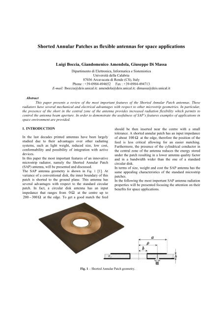
The SAP antenna geometry is shown in Fig. 1 [1]. At<br />
variance of a conventional disk, the inner boundary of this<br />
patch is shorted to the ground plane. This antenna h<strong>as</strong><br />
several advantages with respect to the standard circular<br />
patch. In fact, a circular disk antenna h<strong>as</strong> an input<br />
impedance that ranges from 0 Ω at the centre up to<br />
200 − 300 Ω at the edge. To get a good match the feed<br />
Fig. 1 – <strong>Shorted</strong> <strong>Annular</strong> Patch geometry.<br />
should be then inserted near the centre with a small<br />
tolerance. A shorted annular patch h<strong>as</strong> an input impedance<br />
of about 100 Ω at the edge, there<strong>for</strong>e the position of the<br />
feed is less critical allowing <strong>for</strong> an e<strong>as</strong>ier matching.<br />
Furthermore, the presence of the cylindrical conductor in<br />
the central zone of the antenna reduces the energy stored<br />
under the patch resulting in a lower antenna quality factor<br />
and in a bandwidth wider than the one of a standard<br />
circular disk.<br />
In terms of size, weight and cost the SAP antenna h<strong>as</strong> the<br />
same appealing characteristics of the standard microstrip<br />
patches.<br />
In the following the most important SAP antenna radiation<br />
properties will be presented focusing the attention on their<br />
benefits <strong>for</strong> <strong>space</strong> <strong>applications</strong>.
2. SAP CHARACTERISTICS<br />
SAP antenn<strong>as</strong> have been extensively studied <strong>for</strong> their<br />
property to inhibit surface wave radiation. In [2] it h<strong>as</strong><br />
been demonstrated that an appropriate selection of the<br />
SAP ring external radius inhibits the excitation of the TM0<br />
surface wave mode avoiding the radiation pattern<br />
deterioration due to the surface waves diffraction and<br />
reducing mutual coupling in array <strong>applications</strong> [3]. The<br />
theory h<strong>as</strong> been extended to elliptical SAP, <strong>for</strong> dual band<br />
or circularly polarized antenn<strong>as</strong>, in [4].<br />
Another essential feature of the antenna is that the SAP<br />
pattern can be e<strong>as</strong>ily controlled varying the antenna<br />
geometry without degrading the radiation characteristics.<br />
In order to clarify this <strong>as</strong>pect, let us first consider a<br />
conventional circular patch antenna resonating on its<br />
dominant mode TM11. Once the resonant frequency and<br />
the dielectric characteristics are given, the external radius<br />
of the disk it is uniquely determined and the antenna<br />
radiation pattern, strictly connected to the magnetic current<br />
distribution at the external edge of the patch, can not be<br />
varied.<br />
On the contrary, the shorted annular patch, which h<strong>as</strong> the<br />
same magnetic current distribution of a conventional disk,<br />
offers much more flexibility in shaping the radiation<br />
pattern. In fact, with a proper choice of the external and<br />
internal radii, narrower beams that maintain the radiation<br />
characteristics of a circular disk can be obtained.<br />
As example, three shorted annular patch antenn<strong>as</strong><br />
resonating at the nominal GPS L1 frequency,<br />
1.57542GHz, with an external radius of 35, 45, and 55.7<br />
mm, have been designed considering a substrate with<br />
dielectric constant ε R =2.55 and thickness of 3.2 mm. The<br />
effect of a larger external radius is shown in Fig. 2 where<br />
the co-polar radiation patterns of the three SAP antenn<strong>as</strong><br />
have been compared with the one of a conventional<br />
circular patch resonating at the same frequency and<br />
designed using the same substrate. As expected, a larger<br />
outer radius of the antenna results in a narrower beam.<br />
Fig. 2 – SAP radiation pattern flexibility.<br />
Another important feature of the proposed antenna is that<br />
the gain of the shorted patch is considerably higher than<br />
other conventional microstrip antenn<strong>as</strong>. For instance, the<br />
circular patch antenna taken <strong>as</strong> reference in Fig. 2 h<strong>as</strong> a<br />
gain of 6.8dB while the SAP’s gain varies with the outer<br />
radius of the ring following the curve reported in Fig. 3 and<br />
attaining a maximum of 10.67dB.<br />
Fig. 3 – SAP gain vs. outer radius.<br />
In addition to the radiation properties, the SAP antenna<br />
h<strong>as</strong> mechanical features highly beneficial <strong>for</strong> <strong>space</strong><br />
<strong>applications</strong>. In fact, even if the SAP designs proposed in<br />
this paper have been developed using a conventional<br />
microstrip technology, they can be e<strong>as</strong>ily adapted to<br />
solutions employing suspended technology and high<br />
per<strong>for</strong>mance materials. This opportunity eliminates the<br />
problems arising from the sensitivity of the electrical<br />
characteristics of the substrates and the distortion<br />
generated by the diffraction of surface waves seems to be<br />
advisable. This configuration is e<strong>as</strong>ily accomplished <strong>as</strong> the<br />
central short provides a supporting element on which<br />
single or stacked SAP’s can be build.<br />
As a further advantage of the shorted ring with respect to<br />
other microstrip geometries, it should be noticed that the<br />
central short provides a path <strong>for</strong> ESD avoiding the creation<br />
of ad-hoc circuits.<br />
3. APPLICATIONS<br />
So far, the SAP antenna h<strong>as</strong> been successfully applied to<br />
several aero<strong>space</strong> <strong>applications</strong>.<br />
High Directive Antenn<strong>as</strong><br />
The gain incre<strong>as</strong>e combined with the possibility to control<br />
the beam aperture can result highly beneficial in designing<br />
directive antenn<strong>as</strong> of small and medium satellites.<br />
Normally <strong>for</strong> these <strong>applications</strong> where beam widths around<br />
50degrees and a gain around 12 dB are needed, small<br />
array of printed antenn<strong>as</strong> are employed. The same<br />
requirements can be e<strong>as</strong>ily satisfied in a more efficient way
using a single stacked SAP antenna. With this solution the<br />
beam aperture can be shaped by opportunely selecting the<br />
antenna outer radius and a par<strong>as</strong>tic patch can be used to<br />
further incre<strong>as</strong>e the antenna gain.<br />
High precision GPS<br />
In the l<strong>as</strong>t few years the Global Positioning System (GPS)<br />
h<strong>as</strong> been used in a variety of <strong>applications</strong> <strong>for</strong> which new<br />
and more restrictive requirements <strong>for</strong> the design of the<br />
receiving antenna have been introduced. In particular, <strong>for</strong><br />
high-precision GPS <strong>applications</strong>, such <strong>as</strong> differential GPS,<br />
GPS-b<strong>as</strong>ed <strong>space</strong>craft attitude determination or geodetic<br />
surveying, a receiving antenna with superior rejection to<br />
multipath signals is required.<br />
At the radiator level, multipath can be essentially<br />
controlled in two ways. Antenn<strong>as</strong> with a good rejection of<br />
LHCP signals can potentially eliminate multipath effects<br />
arising from direct reflections. Additionally, considering<br />
that reflections often impinge on the antenna at low<br />
elevations, the multipath rejection per<strong>for</strong>mance can be<br />
improved by shaping the antenna gain pattern to reject<br />
low-elevation signals while ensuring adequate<br />
hemispherical coverage. Furthermore, in order to satisfy<br />
the demanded precision and reliability, a high-per<strong>for</strong>mance<br />
GPS antenna must be capable of operation at the two GPS<br />
frequencies (L1: 1.57542GHz, L2: 1.2276GHz).<br />
Several low multipath GPS antenn<strong>as</strong> have been proposed<br />
in the p<strong>as</strong>t [5]. Un<strong>for</strong>tunately, most of the available<br />
solutions, including arrays or choke rings, are impractical<br />
in aero<strong>space</strong> <strong>applications</strong> due to the operational<br />
requirements in terms of size and weight. A more effective<br />
design h<strong>as</strong> been proposed in [6] where the shorted annular<br />
patch antenna, h<strong>as</strong> been introduced <strong>as</strong> a possible solution<br />
<strong>for</strong> low-multipath GPS <strong>applications</strong>.<br />
As shown in Fig. 2 the SAP radiator offers an extended<br />
radiation pattern flexibility which can be used to optimize<br />
the multipath rejection per<strong>for</strong>mances in consideration of<br />
the specific application constrains.<br />
In order to demonstrate the radiation characteristics of the<br />
shorted patches, the experimental results referred to the<br />
SAP antenna having an external radius of 35mm are<br />
presented. A prototype h<strong>as</strong> been fabricated using a<br />
standard milling drilling machine. An Arlon Diclad<br />
layer ( ε r = 2.<br />
55 ; h=3.2mm) h<strong>as</strong> been used to etch the<br />
patch. The inner hole h<strong>as</strong> been machined into the two<br />
dielectrics and the short circuit h<strong>as</strong> been obtained using<br />
soldered copper foil. Adequate circular polarization purity<br />
is attained by feeding the antenna by means of two 50 Ω<br />
coaxial probes located 90 deg. apart and having 90 deg. of<br />
ph<strong>as</strong>e difference. The inner radius and the feed location<br />
are 6mm and 12mm respectively. The me<strong>as</strong>ured input<br />
impedance of the antenna is presented in Fig. 5, in<br />
comparison with the results of a FEM b<strong>as</strong>ed commercial<br />
simulator [9]. As it can be seen, the predicted result is in<br />
excellent agreement with the experimental values.<br />
Due to the precision of the simulator and the accuracy of<br />
the fabrication process, it w<strong>as</strong> possible to achieve a fairly<br />
precise design that provided predictably high per<strong>for</strong>mance.<br />
In fact, the antenna resonates at the nominal GPS L1<br />
frequency and is very well matched.<br />
The multipath rejection per<strong>for</strong>mances of the SAP<br />
prototype have been evaluated considering both the<br />
sharpness of the antenna pattern toward the horizon and<br />
the circular polarisation purity over the whole radiation<br />
hemisphere.<br />
Fig. 4 - Me<strong>as</strong>ured and simulated radiation patterns.<br />
Fig. 5 - Simulated and me<strong>as</strong>ured input impedance.
The me<strong>as</strong>ured and simulated radiation patterns, reported in<br />
Fig. 4, show that the proposed SAP antenna h<strong>as</strong>, <strong>as</strong><br />
expected, an amplitude roll-off from boresight to horizon<br />
of about 15dB. It is important to note that this result,<br />
which provides a wide hemispherical coverage while<br />
sufficiently rejecting grazing signals, h<strong>as</strong> been obtained<br />
using a 14 cm square ground plane so without incre<strong>as</strong>ing<br />
the overall dimension of the antenna. In addition to the<br />
sharpness of the radiation pattern, the SAP prototype<br />
proposed in this paper fully satisfies the polarization purity<br />
constrains required <strong>for</strong> high precision GPS <strong>applications</strong>. In<br />
fact, the axial ratio stays below 2dB within the entire<br />
coverage hemisphere.<br />
Other geometrical configurations of SAP antenn<strong>as</strong> have<br />
been proposed <strong>for</strong> high precision GPS <strong>applications</strong>. In [7]<br />
the features of the shorted annular elliptical patch antenna<br />
(SAEP) have been shown demonstrating that an effective<br />
low multipath design can be obtained using a single<br />
coaxial feed. As an extension of that design a dual band<br />
SAEP h<strong>as</strong> been presented in [8]. In this latter c<strong>as</strong>e two<br />
shorted elliptical rings have been arranged in a stacked<br />
configuration to provide dual frequency operation.<br />
SAP <strong>for</strong> Radio occultation <strong>applications</strong><br />
The implementation of the GPS network of satellites h<strong>as</strong><br />
created an opportunity <strong>for</strong> active remote sounding of the<br />
earth’s atmosphere by radio occultation. In radio<br />
occultation, the ray path of a radio signal emitted by one<br />
satellite and received at another satellite in low orbit<br />
(LEO) p<strong>as</strong>ses through the atmosphere when the LEO<br />
satellite sets behind the Earth. The signals are delayed <strong>as</strong><br />
they travel through the atmosphere because the refractivity<br />
varies <strong>as</strong> a function of pressure, temperature, and water<br />
vapour pressure. These delays in the GPS signals are<br />
me<strong>as</strong>ured in order to extract atmospheric properties<br />
through an inversion process.<br />
Active remote sounding of the earth’s atmosphere by radio<br />
occultation require high per<strong>for</strong>mances and different modes<br />
of operation, thus the development of suitable instruments<br />
is needed. In particular, the antenn<strong>as</strong> <strong>for</strong> a radio<br />
occultation me<strong>as</strong>urement require shaped beams to<br />
maximize the gain along the curved limb of the earth.<br />
Typically, the antenna the beam in the elevation and<br />
azimuth plane must be localized between -27.8° < θ < -10<br />
and -53° < φ < 53° <strong>for</strong> both the GPS frequencies. To fulfil<br />
the radio occultation radiation requirements a number of<br />
stacked shorted annular patch antenn<strong>as</strong> can be used to<br />
<strong>for</strong>m a linear array. In this configuration the radiation<br />
pattern flexibility of the shorted annular patch antenn<strong>as</strong><br />
can be highly beneficial in reducing the overall dimension<br />
of the array. In fact, the azimuthal radiation pattern<br />
constraints can be en<strong>for</strong>ced by opportunely selecting the<br />
outer radii of the SAP elements while the elevation<br />
shaping is controlled by the array factor. Once again, the<br />
<strong>flexible</strong> radiation properties of the SAP antenna allows <strong>for</strong><br />
a <strong>space</strong> and complexity reduction with respect to other<br />
microstrip geometries.<br />
4. CONCLUSIONS<br />
The <strong>Shorted</strong> <strong>Annular</strong> Patch antenna is an innovative<br />
radiator. In addition to the features of the microstrip<br />
technology, the shorted ring h<strong>as</strong> incre<strong>as</strong>ed radiation<br />
flexibility and mechanical properties more suitable to<br />
aero<strong>space</strong> <strong>applications</strong>.<br />
REFERENCES<br />
[1] G. Di M<strong>as</strong>sa, G. Mazzarella, “<strong>Shorted</strong> <strong>Annular</strong> Patch<br />
Antenna”, MOTL, Vol.8 March 1995<br />
[2] D. R. Jackson, J. T. Williams, Arun K. Bhattacharyya,<br />
Richard L. Smith, Stephen J. Buchheit & S. A. Long,<br />
“Microstrip Patch Designs that do not excite Surface<br />
Waves”, IEEE Trans. On AP, Vol. 41 No.8 Aug 1993<br />
[3] M. Khayat, D. R. Jackson, J. T. Williams, “Mutual<br />
Coupling Between Reduced Surface-Wave Microstrip<br />
Antenn<strong>as</strong>”, IEEE Trans. On AP, Vol. 48, No. 10, Oct<br />
2000<br />
[4] G. Amendola, L. Boccia, G. Di M<strong>as</strong>sa, “Surface<br />
Wave Radiation from a <strong>Shorted</strong> Elliptical Patch<br />
Antenna” - IEEE AP-S, Volume: 2 , 2003<br />
[5] A. M. Dinius - “GPS antenna multipath rejection<br />
per<strong>for</strong>mance”, Lincoln Laboratory Report, Aug 1995<br />
[6] L. Boccia, G. Amendola, G. Di M<strong>as</strong>sa, L. Giulicchi –<br />
“<strong>Shorted</strong> <strong>Annular</strong> patch antenn<strong>as</strong> <strong>for</strong> multipath<br />
rejection in GPS-b<strong>as</strong>ed attitude determination”,<br />
MOTL, January 2001.<br />
[7] L. Boccia, G. Amendola, G. Di M<strong>as</strong>sa – “A shorted<br />
elliptical patch antenna <strong>for</strong> GPS <strong>applications</strong>” – to be<br />
published on IEEE Antenn<strong>as</strong> and Wireless<br />
Propagation Letters<br />
[8] L. Boccia; G. Amendola; G. Di M<strong>as</strong>sa – “A highper<strong>for</strong>mance<br />
dual frequency microstrip antenna <strong>for</strong><br />
global positioning system”- APS, 2001 IEEE<br />
International Symposium , Volume: 4 , 2001<br />
[9] HFSS v8 – Ansoft Corporation


