Download PDF - National Grid
Download PDF - National Grid
Download PDF - National Grid

You also want an ePaper? Increase the reach of your titles
YUMPU automatically turns print PDFs into web optimized ePapers that Google loves.
NGTS 2.1<br />
Page 10 Issue 2<br />
May 1995<br />
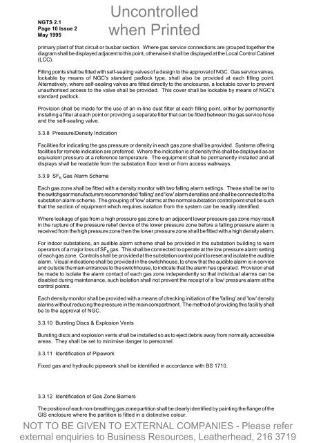
primary plant of that circuit or busbar section. Where gas service connections are grouped together the<br />
diagram shall be displayed adjacent to this point, otherwise it shall be displayed at the Local Control Cabinet<br />
(LCC).<br />
Filling points shall be fitted with self-sealing valves of a design to the approval of NGC. Gas service valves,<br />
lockable by means of NGC's standard padlock type, shall also be provided at each filling point.<br />
Alternatively, where self-sealing valves are fitted directly to the enclosures, a lockable cover to prevent<br />
unauthorised access to the valve shall be provided. This cover shall be lockable by means of NGC's<br />
standard padlock.<br />
Provision shall be made for the use of an in-line dust filter at each filling point, either by permanently<br />
installing a filter at each point or providing a separate filter that can be fitted between the gas service hose<br />
and the self-sealing valve.<br />
3.3.8 Pressure/Density Indication<br />
Facilities for indicating the gas pressure or density in each gas zone shall be provided. Systems offering<br />
facilities for remote indication are preferred. Where the indication is of density this shall be displayed as an<br />
equivalent pressure at a reference temperature. The equipment shall be permanently installed and all<br />
displays shall be readable from the substation floor level or from access walkways.<br />
3.3.9 SF 6 Gas Alarm Scheme<br />
Each gas zone shall be fitted with a density monitor with two falling alarm settings. These shall be set to<br />
the switchgear manufacturers recommended 'falling' and 'low' alarm densities and shall be connected to the<br />
substation alarm scheme. The grouping of 'low' alarms at the normal substation control point shall be such<br />
that the section of equipment which requires isolation from the system can be readily identified.<br />
Where leakage of gas from a high pressure gas zone to an adjacent lower pressure gas zone may result<br />
in the rupture of the pressure relief device of the lower pressure zone before a falling pressure alarm is<br />
received from the high pressure zone then the lower pressure zone shall be fitted with a high density alarm.<br />
For indoor substations, an audible alarm scheme shall be provided in the substation building to warn<br />
operators of a major loss of SF 6 gas. This shall be connected to operate at the low pressure alarm setting<br />
of each gas zone. Controls shall be provided at the substation control point to reset and isolate the audible<br />
alarm. Visual indications shall be provided in the switchhouse, to show that the audible alarm is in service<br />
and outside the main entrances to the switchhouse, to indicate that the alarm has operated. Provision shall<br />
be made to isolate the alarm contact of each gas zone independently so that individual alarms can be<br />
disabled during maintenance, such isolation shall not prevent the receipt of a 'low' pressure alarm at the<br />
control points.<br />
Each density monitor shall be provided with a means of checking initiation of the 'falling' and 'low' density<br />
alarms without reducing the pressure in the main compartment. The method of providing this facility shall<br />
be to the approval of NGC.<br />
3.3.10 Bursting Discs & Explosion Vents<br />
Bursting discs and explosion vents shall be installed so as to eject debris away from normally accessible<br />
areas. They shall be set to minimise danger to personnel.<br />
3.3.11 Identification of Pipework<br />
Fixed gas and hydraulic pipework shall be identified in accordance with BS 1710.<br />
3.3.12 Identification of Gas Zone Barriers<br />
The position of each non-breathing gas zone partition shall be clearly identified by painting the flange of the<br />
GIS enclosure where the partition is fitted in a distinctive colour.