Dual-pipeline heterogeneous ASIP design - School of Computer ...
Dual-pipeline heterogeneous ASIP design - School of Computer ...
Dual-pipeline heterogeneous ASIP design - School of Computer ...
You also want an ePaper? Increase the reach of your titles
YUMPU automatically turns print PDFs into web optimized ePapers that Google loves.
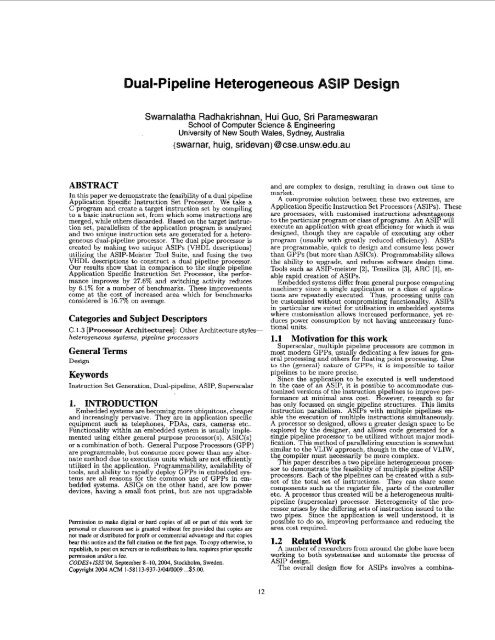
ABSTRACT<br />
<strong>Dual</strong>-Pipeline Heterogeneous A IP Design<br />
Swarnalatha Radhakrishnan, Hui Guo, Sri Parameswaran<br />
<strong>School</strong> <strong>of</strong> <strong>Computer</strong> Science & Engineering<br />
University <strong>of</strong> New South Wales, Sydney, Australia<br />
{swarnar, huig, sridevan}@cse.unsw.edu.au<br />
~~~~~~~~~~~~ ~~~<br />
merged, while others discarded. Based on the target instruction<br />
set, parallelism <strong>of</strong> the application program is analyzed<br />
and two unique instruction sets are generated for a <strong>heterogeneous</strong><br />
dual-<strong>pipeline</strong> processor. The dual pipe processor is<br />
created bv makine two uniaue <strong>ASIP</strong>s (VHDL descrintionsi<br />
I . ~<br />
Application Specific InstructiAn Set Processor, %he performance<br />
improves by 27.6% and switching activity reduces<br />
by 6.1% for a number <strong>of</strong> benchmarks. These improvements<br />
come at the cost <strong>of</strong> increased area which for benchmarks<br />
considered is 16.7% on average.<br />
Categories and Subject Descriptors<br />
C.1.3 [Processor Architectures]: Other Architecture styles~<br />
<strong>heterogeneous</strong> systems, <strong>pipeline</strong> processors<br />
General Terms<br />
Design<br />
Keywords<br />
Instruction Set Generation, <strong>Dual</strong>-<strong>pipeline</strong>, <strong>ASIP</strong>, Superscalar<br />
1. INTRODUCTION<br />
Embedded systems are becoming more ubiquitous, cheaper<br />
and increasingly pervasive. They are in application specific<br />
equipment such as telephones, PDAs, cars, cameras etc..<br />
Functionality within an embedded system is usually imple-<br />
mented using either general purpose processor(s), ASIC(s)<br />
or a combination <strong>of</strong> both. General Purpose Processors (GPP)<br />
are programmable, hut consume more power than an alter-<br />
nate method due to execution units which are not ediently<br />
utilized in the application. Programmability, availability <strong>of</strong><br />
tools, and ability to rapidly deploy GPPs in embedded sys-<br />
tems are all reasons for the common use <strong>of</strong> GPPs in em-<br />
bedded systems. ASICs on the other hand, are low power<br />
devices, having a small foot print, but are not upgradable<br />
Permission to make digital or hard copies <strong>of</strong> all or part <strong>of</strong> this work for<br />
personal or classmm use is granted without fee provided that copies are<br />
not made or distributed for pr<strong>of</strong>it or commercial advantage and that copies<br />
bear this notice and the full cimtian on ihe first page. To copy otherwise, to<br />
republish, to post on servers or to redisiribute to lists, requires prior specific<br />
12<br />
and are complex to <strong>design</strong>, resulting in drawn out time to<br />
market.<br />
A compromise solution between these two extremes, are<br />
Application Specific Instruction Set Processors (<strong>ASIP</strong>s). These<br />
are processors, with customised instructions advanta eous<br />
to the particular program or class <strong>of</strong> programs. An AS18 will<br />
execute an application with great efficiency for which it was<br />
<strong>design</strong>ed, though they are capable <strong>of</strong> executing any other<br />
program (usually with greatly reduced efficiency). <strong>ASIP</strong>s<br />
are programmable, quick to <strong>design</strong> and consume less power<br />
than GPPs (but more than ASICs). Programmability allows<br />
the ability to upgrade, and reduces s<strong>of</strong>tware <strong>design</strong> time.<br />
Tools such as <strong>ASIP</strong>-meister [Z], Tensilica [3], ARC [l], enable<br />
rapid creation <strong>of</strong> <strong>ASIP</strong>s.<br />
Embedded systems differ from general pur ose computing<br />
machinery since a single application or a cyass <strong>of</strong> applications<br />
are repeatedly executed. Thus, rocessin units can<br />
be customised without compromising Rnctionagt <strong>ASIP</strong>s<br />
in particular are suited for utilisation in embeddegsystems<br />
where customisation allows increased performance, yet reduces<br />
power consumption by not having unnecessary functional<br />
units.<br />
1.1 Motivation for this work<br />
Superscalar, multiple <strong>pipeline</strong> processors are common in<br />
most modern GPPs, usual1 dedicating a few issues for en<br />
eral processing and others 6, floating point processing. %U;<br />
to the (general) nature <strong>of</strong> GPPs, it is impossible to tailor<br />
<strong>pipeline</strong>s to be more precise.<br />
Since the application to be executed is well understood<br />
in the case <strong>of</strong> an <strong>ASIP</strong>, it is possible to accommodate customized<br />
versions <strong>of</strong> the instruction <strong>pipeline</strong>s to improve performance<br />
at minimal area cost. However, research so far<br />
has only focussed on single <strong>pipeline</strong> structures. This limits<br />
instruction parallelism. <strong>ASIP</strong>s with multiple pi elines enable<br />
the execution <strong>of</strong> multiple instructions simukaneously.<br />
A processor so <strong>design</strong>ed, allows a greater <strong>design</strong> space to be<br />
explored b the <strong>design</strong>er, and allows code generated for a<br />
single pipeke processor to be utilized without major modification.<br />
This method <strong>of</strong> paralleliziug execution is somewhat<br />
similar to the VLIW approach, though in the case <strong>of</strong> VLIW,<br />
the compiler must necessarily be more complex.<br />
This aper describes a two <strong>pipeline</strong> <strong>heterogeneous</strong> processor<br />
to Amonstrate the feasibility <strong>of</strong> multiple <strong>pipeline</strong> <strong>ASIP</strong><br />
processors. Each <strong>of</strong> the <strong>pipeline</strong>s can be created with a sub<br />
set <strong>of</strong> the total set <strong>of</strong> instructions. They can share some<br />
components such as the register file, parts <strong>of</strong> the controller<br />
etc. A processor thus created will be a <strong>heterogeneous</strong> multi<strong>pipeline</strong><br />
(superscalar) processor. Heterogeneity <strong>of</strong> the processor<br />
arises by the differing sets <strong>of</strong> instruction issued to the<br />
two ?,pes. Since the application is well understood, it is<br />
possi e to do so, improving performance and reducing the<br />
area cost required.<br />
1.2 Related Work<br />
A number <strong>of</strong> researchers from around the globe have been<br />
workin to both systematise and automate the process <strong>of</strong><br />
<strong>ASIP</strong> &sign.<br />
The overall <strong>design</strong> flow for <strong>ASIP</strong>s involves a combina-
~<br />
tiou <strong>of</strong> instruction generation and <strong>design</strong> space exploration<br />
tools. In [4, 17, 221 tool suites take a specification (written<br />
in an architectural description language) and generate re-<br />
targetable compilers, instruction set simulators (ISS) <strong>of</strong> the<br />
target architecture, and synthesisable HDL models <strong>of</strong> the<br />
target processor. The generated tools allow valid assembly<br />
code generation and performance estimation for each spec-<br />
ified architecture. In [21] the <strong>design</strong> flow consists <strong>of</strong> gener-<br />
ating instructions automatically, inserting instructions, and<br />
performing a heuristic <strong>design</strong> space exploration. Automatic<br />
instruction generation locates the regular templates derived<br />
~~ ~~~~ ~~~~~ ~~~~<br />
~ ~~~ ~<br />
are rankkd, and thi hyghest ranking blocks are imple&nt'ed<br />
as instructions.<br />
In [6], the authors searched for regularity in sequential,<br />
parallel and combined sequential/parallel hasic instructions<br />
in a dataflow graph. New sets <strong>of</strong> instructions were gener-<br />
ated by combining basic instructions. Kastner et al. in [14]<br />
searched for an optimal cover <strong>of</strong> a set <strong>of</strong> regular instructions,<br />
and then constructed an optimal set <strong>of</strong> sequential instruc-<br />
tions. Zhao et al. in [23] used static resource models to<br />
explore possible new instructions that can be added to the<br />
data path to enhance erformance.<br />
A system called PEAS-I11 for the creation <strong>of</strong> <strong>pipeline</strong>d<br />
<strong>ASIP</strong>s is described in [16]. A parallel and scalable <strong>ASIP</strong> ar-<br />
chitecture suitable for reactive systems is described in [19].<br />
A novel approach to select the Intellectual Properties (IP)<br />
and interfaces for an <strong>ASIP</strong> core to accelerate the applica-<br />
tion is proposed in [7]. A Hardwarels<strong>of</strong>tware partitioning<br />
algorithm for automatic synthesis <strong>of</strong> a <strong>pipeline</strong>d <strong>ASIP</strong> with<br />
multiple identical functional units with area constraints is<br />
introduced in [5]. The code generation for time critical loops<br />
for Very Large Instruction Word (VLIW) <strong>ASIP</strong>s with het-<br />
erogenous distributed register structure is addressed in [ll].<br />
In 1121 a methodolow for earlv snace exoloration af VLIW<br />
architecture is presented in [9]. In[S] using power estimation<br />
techniques from high level synthesis, a low power <strong>ASIP</strong> is<br />
synthesized from a customized ASIC. Case study <strong>of</strong> power<br />
reduction is given in [lo]. Evaluation <strong>of</strong> the effect <strong>of</strong> register<br />
file size in <strong>ASIP</strong> performance and power is done in (131.<br />
In 1151, Kathail et al. proposed a <strong>design</strong> flow for a VLIW<br />
processor consisting <strong>of</strong> a selection <strong>of</strong> Non-Programmable<br />
hardware Accelerators (NPAs), <strong>design</strong> space exploration <strong>of</strong><br />
implementing different combinations <strong>of</strong> NPAs, and evaluation<br />
<strong>of</strong> the <strong>design</strong>s. An NPA is a co-processor for functions<br />
expressed as compute-intensive nested loops in C.<br />
In [20] the author discusses a decoupled Access/Execute<br />
architecture, with two computation units containing own<br />
instruction streams. The processor decouples data accesses<br />
and execution (for example ALU instructions). One <strong>of</strong> them<br />
does all the memory operations, while both can perform<br />
non-memory access operations. The architecture issues two<br />
instructions per clock cycle. The two instruction streams<br />
communicate via architectural queues.<br />
Our architecture is somewhat similar to the one proposed<br />
in [20]. We customise the processor for a particular application,<br />
while the processor in [20] is generic. They use separate<br />
register files for each pipe, with a common copy area. We<br />
use a global register file. We also avoid an instruction queue,<br />
preferring a compile time schedule <strong>of</strong> instructions and avoid<br />
data hazards by inserting NOPs appropriately.<br />
1.3 Contributions<br />
For the first time we create a dual <strong>pipeline</strong> <strong>ASIP</strong> and<br />
demonstrate that it is feasible to utilize such a processor to<br />
extend the <strong>design</strong> space <strong>of</strong> an application. In particular:<br />
13<br />
a simple <strong>heterogeneous</strong> architecture has been proposed<br />
with data access instructions allocated to one pipe,<br />
instruction fetch and branch instructions allocated to<br />
the other pipe, and all other instructions implemented<br />
on one or both pipes (note we have an ALU on one<br />
pipe, and if necessary some <strong>of</strong> the operations within<br />
the ALU can be duplicated on the other);<br />
and, a methodology containing an algorithm with poly-<br />
nomial complexity has been proposed to determine<br />
which instructions should he in both pipes.<br />
1.4 _Paoer _ Organizatinn<br />
~~ ~~<br />
The rest <strong>of</strong> the paper is organized in the following way.<br />
Section 2 describes the architecture template <strong>of</strong> the dual<br />
nioeline Drocessor to be imolemented. The ~~~~ followine ~~~~~<br />
secii&<br />
desciibes the methodoldgy taken to <strong>design</strong> dual $&%ne<br />
processor. Simulations and results are given in section 4. Finally,<br />
the paper is concluded in section 5.<br />
2. ARCHITECTURE<br />
Our goal is to <strong>design</strong> an application-specific dual <strong>pipeline</strong><br />
processor to improve performance, reduce energy consump-<br />
tion with minimal area penalty.<br />
The architecture template adopted is shown in Figure 1.<br />
.I REGlSTERFlLE I.<br />
I I<br />
Figure 1: Architecture Template<br />
The two-pi eline rocessor has two functional data paths.<br />
Both paths &are de same register file, data memory and<br />
instruction memort The register file has two-ports to enable<br />
data traffic on bot <strong>pipeline</strong> paths at the same time.<br />
The control unit &-one orthe <strong>pipeline</strong>s, controls the instruction<br />
fetch from the instruction memory and dispatches<br />
instructions to both paths. The other path controls data<br />
memory access to transfer data between register file and<br />
data memory. Each path has a separate control unit that<br />
controls the oDeratiou <strong>of</strong> the ~ related ~ ~~~ ~~ functional units on that<br />
path. We sepirate the instruction fetch and data fetch into<br />
two separate pipes to reduce the controller complexity. Some<br />
instructions will appear on both paths. The functional units<br />
in each path are determined by the instruction set desianed<br />
is possible to execute two add instructions simultaneously,<br />
one hy the ALU on the left and one on the adder on the<br />
right. A methodolo for determining the functional units<br />
that havr ~~~ ~ to ~ be dunKatrd ~~ ~~~~ is ~~ riven in section 3.<br />
Based on the arhitectnre, attempt:<br />
to efficiently exploit parallelism by dual <strong>pipeline</strong>s;
to minimize additional area cost;<br />
and, to minimize the total energy consumption.<br />
3. METHODOLOGY<br />
Our <strong>design</strong> approach for a given application consists <strong>of</strong><br />
three tasks: target instruction set generation (Phase I);<br />
dual <strong>pipeline</strong> instruction set creation (Phase 11); and, dual<br />
<strong>pipeline</strong> <strong>ASIP</strong> construction and code generation (Phase 111).<br />
The <strong>design</strong> flow is shown in Figure 2.<br />
Figure 2: Design Flow<br />
3.1 Target Instruction Set Generation<br />
The first step <strong>of</strong> the methodology is the identification <strong>of</strong><br />
the target instruction set. This step is marked Phase I in<br />
Fi ure 2.<br />
% C program is compiled and assembly code is produced<br />
for a base RISC machine. The instruction set is first reduced<br />
by eliminating all un-used instructions<br />
~~~~~~~ r~~~~~~~~~<br />
~~ ..... ~.. .<br />
WlheFe possible; a spechzed instruction is created for ea&<br />
<strong>of</strong> these blocks, and replaces them. However, specialized<br />
instructions may require more functional units in the processor;<br />
resulting in extra chip area. Therefore we create<br />
instructions only for those blocks with hi h execution frc<br />
quency, such as blocks within loops. Metfods for creation<br />
<strong>of</strong> specialized instructions are given in [18] and [Zl].<br />
Figure 3 gives an exam le <strong>of</strong> how an assembly code is<br />
transformed by replacing hpocks by specialized instructions.<br />
Figure 3(a), shows an assembly code (AC) <strong>of</strong> a loop body<br />
produced by a compiler (the code was slightly modified to<br />
enhance explanation <strong>of</strong> methodology). Without loss <strong>of</strong> functional<br />
correctness, some instructions ( in hold font) are reordered<br />
(RAC - reordered assembly code), as shown in Figure<br />
3(h). Figure 3(b) contains six basic blocks (in rectangles).<br />
These blocks can be divided into two groups: G1<br />
and G2. Blocks in G1 - load data to a register from memory<br />
using an indirect addressing mode with an <strong>of</strong>fset. G2<br />
stores data to memory from a register, the memory is also<br />
addressed indirectly with an o set For these blocks, two new<br />
instructions are generated: &dr&nd Sstr. By merging instructions<br />
in those blocks, we obtain the new code as shown<br />
in Figure 3(c) (NAC - new assembly code), where highlighted<br />
new instructions replace the corresponding blocks in<br />
Figure 3(b).<br />
Thus final instruction set is given in Figure 4, as the target<br />
instruction set (TIS) <strong>of</strong> the processor for the example given<br />
in Figure 3.<br />
14<br />
no" rl, r7<br />
sub n, i.1,XB<br />
nI0" r;, ri<br />
sub r3. r3. XI2<br />
Idr r3, Ir31<br />
iSi =2. r3. 112<br />
sub r3. Ti. #a<br />
Idr r3. Ir31<br />
add r3. r2. r;<br />
Idr r2, lrll<br />
Idr r?. Iril<br />
cmp r2, r3<br />
ble .L4<br />
my1 ro. r5<br />
mu1 r5. r6<br />
ma" r1, r,<br />
sub rl, rl, #*<br />
rnOY r3. r7<br />
sub r3. r3. U12<br />
Idr r3. lr31<br />
IS1 r2, r3. #2<br />
sub r3. r7, YP<br />
Idr r3, Ir31<br />
add r3, r2. r3<br />
Idr r3, lr3l<br />
str r3. lrll<br />
"'0" rl. r3<br />
"'0" ro. r3<br />
GI "'0" r3. ri<br />
sub r3, r3, 112<br />
Idr r3. lr31<br />
IS1 r2. r3. 12<br />
Cl- sub r3, r7. +44<br />
Idr r3, [r3l<br />
add r3. r2. r3<br />
D1 rnOY rl, r7<br />
sub n, rl, #8<br />
ldr r2. Irll<br />
Idr r3. Ir3l<br />
cmp r2. r3<br />
ble .L4<br />
"'"1 ro. r5<br />
mu1 r5. r6<br />
61 "'0" r3. ri<br />
sub r3, r3. 1112<br />
Idr r3. Ir31<br />
IS1 r2, r3. U2<br />
GI- sub r?, ri. 84<br />
Idr r3, Ir31<br />
add r3. r2. r3<br />
Idr r3. ir31<br />
02 me" rl, r,<br />
e* rl, rl, XB<br />
SLI r3, Irll<br />
"'0" rl, r3<br />
lb)<br />
"IO" r7, ro<br />
mow r6. rl<br />
Sldrrl. Ir7, 1111<br />
IS1 r2. r3. :2<br />
Sldrrl. 1x7, 111<br />
add r3. r2. r3<br />
SldrXl, 1r7. XB<br />
ldr r3, Ir31<br />
cmp r2. r3<br />
ble .L4<br />
91drr3, Ir?. 1111<br />
IS1 r2. r3. 42<br />
mr3, Ir7. 141<br />
add r3. rZ, r3<br />
Idr r3, ir3i<br />
sstrr3. 1r7, lis1<br />
"IO" r1. r3<br />
rn0" ro. r3<br />
Figure 3: Specific Instruction Generation<br />
(a)Original Assembly Code @)Reordered As-<br />
sembly Code (c)New Assembly Code<br />
Sldr Rn. [Rm. #NI<br />
Srfr Rn, IRm. #NI<br />
add Rn. Rm.Rn<br />
Idr Rn. [Rml<br />
cmp Rn. Rm<br />
ble addrsrr<br />
mw Rn.Rm I<br />
mu1 Rn. Rm I<br />
Figure 4: Target Instruction Set<br />
3.2 <strong>Dual</strong> Pipeline Instruction Set Generation<br />
<strong>Dual</strong> <strong>pipeline</strong> instruction set generation is where the target<br />
instruction set is divided into two sets (some instructions<br />
can he in both sets). This is shown as Phase I1 in Figure 2.<br />
Given the target instruction set TIS, we proceed to create<br />
a <strong>heterogeneous</strong> dual <strong>pipeline</strong> <strong>ASIP</strong> processor. Both pipes<br />
can have differing instructions, allowin the rocessor to be<br />
small, yet have fast processing speed. fake tie code in Figure<br />
3(c) for example. Instruction cmp can be implemented<br />
in just a single <strong>pipeline</strong>. If cmp is implemented in both<br />
pipes, the extra resource in one path will not be used. Thus<br />
we implement cmp in just one path.<br />
A primitive processor provides functionality for memory<br />
accesses, ALU calculations and control. The memory access<br />
instructions can be paired together with ALU instructions,<br />
and can he scheduled to execute simultaneously, such that a<br />
memor instruction fetches data from memory for later use<br />
by an 2LU instruction, while the ALU instruction produces<br />
results for storage (later) by another memory access instruction.<br />
Therefore, we separate the two pipe instruction sets,<br />
IS1 and IS? by allocating memory ~CCCSS<br />
IC)<br />
instructions to one<br />
<strong>pipeline</strong> and basic ALU instructions to other. Rest <strong>of</strong> the<br />
instructions (ALU, and specially created non-memory ac-<br />
cess instructions) are then spread over the two pipes, with<br />
some overlap <strong>of</strong> instructions in both pi es Branches are<br />
only implemented on the instruction fetc! pipe.<br />
The implementation efficiency <strong>of</strong> an instruction in both<br />
pipes is proportional to the number <strong>of</strong> times that instruction<br />
can be executed in parallel, and is inversely proportional to<br />
the additional area cost <strong>of</strong> the instruction. The more fre-<br />
quently an instruction is executed in parallel with another<br />
instruction <strong>of</strong> the same type, the greater the implementation<br />
efficiency.<br />
We define the following terms, to explain the rest <strong>of</strong> the<br />
paper.<br />
Definition 1: Dependency Graph, G. The graphical rep-
esentation depictin the de endency <strong>of</strong> instructions in an<br />
instruction trace, wfere nocfes represent instructions, and<br />
directed edges represent dependency. A node has a ty e<br />
that corresponds to the type <strong>of</strong> instruction it represents. in<br />
instruction is dependent on another if the first instruction<br />
can only be executed after the second is completed. Some<br />
dependent instructions can he executed simultaneously (for<br />
example see lines 4 and 5 in Figure 6(b), which can he ex+<br />
cuted together due to the <strong>pipeline</strong> execution)<br />
Definition 2: Connected Graph, y. The subgraph <strong>of</strong> G,<br />
where all nodes in<br />
are connected by directed edges.<br />
Definition 3: lssociated Graph Set, 9. The set <strong>of</strong> con-<br />
nected graphs that contain nodes <strong>of</strong> a given type. For an<br />
instruction, Insl in the instruction set, its Assoczated Graph<br />
Set is denoted by Pi.<br />
Definition 4: Dependency Depth. The depth <strong>of</strong> a node<br />
in a connected gra h, y, from the starting nodes. A starting<br />
node is not de enzent on any other nodes and has a depth<br />
<strong>of</strong> 1. The totardepth <strong>of</strong> graph g is denoted by d,.<br />
Figure 5: Example <strong>of</strong> Instruction Graph<br />
Y . I<br />
Graph Set, QI = {gl,yZ}. For Ins3, its Associated Graph<br />
set, IS = {gl}. For Insl in suh-graph gl, the depth <strong>of</strong> node<br />
1 is 1 and the depth <strong>of</strong> node 5 is 4.<br />
It is ossible for any instructions with the same dependency<br />
&pth to be grouped in pairs for parallel execution.<br />
Take the instruction nodes 6 and 7 <strong>of</strong> graph 82, in Figure<br />
5, as an example. Both have the same depth, therefore<br />
they can be grou ed into a parallel execution pair. For instructions<br />
in didrent connected raphs, because there is<br />
no dependency, they can always form the parallel execution<br />
pairs. For example, instruction node 6 in g2 can be<br />
paired with any instruction node in gl. But this inter-ymph<br />
matching may result in longer execution. For example, by<br />
grouping instruction nodes 5 and 6, gl and g2 are put in<br />
sequence. The overall execution time will be at least 8 instruction<br />
cycles. As such, it is advisable to match parallel<br />
instructions locally within connected graphs. Only left-over<br />
instructions are considered for inter-graph matching. The<br />
following definition formalizes the parallelizability.<br />
Definition 5: Instmction parallelizability, a. The pu<br />
teutial for an instruction to he executed in parallel with<br />
another instruction <strong>of</strong> the same type. For instruction Ins,,<br />
it is defined as<br />
1<br />
0% = E(LPt +GPi),<br />
(1)<br />
where N is the total number <strong>of</strong> instructions in the target<br />
instruction set; and LPe denotes the intra-graph parallelism<br />
<strong>of</strong> Instruction i, and is defined as<br />
where k, is the number <strong>of</strong> nodes (representing Ins;) <strong>of</strong> depth<br />
j in graph y, I'PliI is the number <strong>of</strong> elements in set 9,; and<br />
(3)<br />
where the first part <strong>of</strong> the product stands for avera e left<br />
over instructions per connected graph. Therefore, GJ, gives<br />
an approximate value <strong>of</strong> possible instruction matching pairs<br />
across the connected graphs.<br />
We use the D value to estimate how <strong>of</strong>ten two <strong>of</strong> the same<br />
instruction type can be scheduled simultaneously.<br />
Definition 6: instmction cost, c. The area overhead,<br />
due to augmenting the basic processor hy implementing the<br />
instruction.<br />
Based on the above definitions, we define the implemen-<br />
tation efficiency for an instruction as follows.<br />
Definition 7: Implementation eficiency, 7. Given an<br />
instruction, Ins,, from the tar et instruction set, assume the<br />
cost for the instruction is c; an$ its parallelizability is, ai, the<br />
implementation efficiency <strong>of</strong> implementing the instruction in<br />
both pipes is qa = o ,/~<br />
In order to determine whether to implement an instruction<br />
in two pipes, we set a criteria value, denoted by 0. An<br />
instruction is implemented in both pi es if 7 2 0. The<br />
value 0 could he derived in many didrent ways. We use<br />
an average-value based scheme by using the average value<br />
<strong>of</strong> o and c over all instructions, which can be implemented<br />
on both <strong>pipeline</strong> paths. Assume the number <strong>of</strong> instructions<br />
(implementable in both paths) in the instruction set is m,<br />
Ins.<br />
2: Is1<br />
mov<br />
mu1<br />
c a 7<br />
E? : :<br />
0.04<br />
0.004<br />
0.12<br />
0<br />
0.22<br />
0.11<br />
0<br />
55<br />
0.92
App. AC AC cc cc SA SA Clk. per Clk.per<br />
Single Parallel Single Parallel Single Parallel Single (ns) Parallel (ns)<br />
~<br />
20547000<br />
8218985<br />
7119392<br />
51202126<br />
14021924<br />
19876018<br />
~<br />
Table 2: Simulation Results<br />
13.104<br />
13.415<br />
12.974<br />
13.049<br />
11.876<br />
13.335<br />
AC % Perf % SA %<br />
Penal. ~ Impr. 1 Red. 1<br />
IS1 /* Algorithm: Given the assembly program (NAC) and<br />
Sldr Rn. rm, *a,<br />
idr m. Is,<br />
sstr m. Is, "ti,<br />
Target Instruction Set (TIS), find two instruction sets,<br />
IS1 and IS2 for two pipes*/<br />
/* Initialize the two instruction sets with Load/Store<br />
ms" m. m instructions and ALU/CTRL instructions in TIS/<br />
IS1 = LoadStore(TISj;<br />
IS2 = ALU(TIS) + CTRL(TIS);<br />
/* Get all non-memory instructions in TIS<br />
and check their area efficiency */<br />
TIS = TIS - ISlUCTRL(TIS);<br />
/' Calculate 7 for each instruction and Theta<br />
CWq, e);<br />
I* Determine whether to imdement instruction in one or two<br />
pipes*/<br />
for all Ins< t TIS<br />
if ni < R<br />
-- .,. - -<br />
/* One pipe. if instruction is<br />
3.3 ~~~l <strong>pipeline</strong> processor and Code G ~ ~ ~ ~ -<br />
ation<br />
Finally we construct the dual <strong>pipeline</strong> processor and gen-<br />
erate machine code for the application. This is shown as<br />
Phase I11 in Figure 2.<br />
Given the two instruction sets, we generate a two-pipe<br />
processor in two steps as illustrated in Figure 8.<br />
Stepl:<br />
Create VHDL descriptions for each instruction set by us-<br />
ing <strong>ASIP</strong>Meister, a single-pipe <strong>ASIP</strong> <strong>design</strong> s<strong>of</strong>tware tool.<br />
The tool takes as input the instruction set, constraints, and<br />
else<br />
an ALU instruction, it is already assi ned to<br />
IS2, no further assimment - is require8<br />
Otherwise, */<br />
if Ins, is not an ALU instruction<br />
IS2 t Ins,:<br />
endif<br />
/* Two pipe impelerntation. If it is an ALU<br />
instruction, further assign it to IS1;<br />
otherwise, assign it to both sets */<br />
if Ins, is not an ALU instruction<br />
IS2 t Ins.:<br />
Fty; 7: <strong>Dual</strong> Instruction Set Generation Aka-<br />
microcode for each instruction, and produces a synthesiz- With the proposed methodology, we desi ned six dual<br />
able VHDL description for the processor. We create two pipe Processors for the following programs: Ereater Corn-<br />
separate processors, one for each instruction set. mon Divisor (GCD), Prime Number Finder (PNF), Ma-<br />
Step2: trix Multiplication (MM), Bubble Sort(BS), InSort(1S) and<br />
Construct the VHDL description for the dual pipe proces- ShellSort(SS).<br />
SOT by modifying and integrating the two single-pipe VHDL The base instruction set chosen was similar to the THUMB<br />
descriptions as per <strong>design</strong>ated architecture shown in Fig- (ARM) instruction set, order to the effective-<br />
ure 1.<br />
The instruction code for the dual pipe processor is gener-<br />
ated by merging the two parallel assembly sequences (cre-<br />
ated during the previous stage - two instruction set gencr-<br />
ation). The merge is performed in two steps. First, each<br />
<strong>of</strong> the two parallel sequences is assembled b the GCC and<br />
object code obtained. Next, the two sets <strong>of</strong>Xinary code for<br />
each <strong>of</strong> the parallel se uences are merged such that a parallel<br />
instruction pair fromzoth sequences forms a single instruc-<br />
tion line. Each line in the code contains two instructions,<br />
one for each <strong>pipeline</strong>, Thus the resulting code forms code<br />
for the two pipe processor.<br />
This phase is presently hand generated, though automa-<br />
tion is possible.<br />
4- SIMULATIONS AND<br />
Figure 8: 2-Pipline Processor Generation<br />
1
Figure 9: 2-pipes .vs. 1-pipe<br />
ness <strong>of</strong> the created two-pipe processors, and our <strong>design</strong> a p<br />
proach, we also implemented those functions with single<br />
pipe <strong>ASIP</strong>s produced by <strong>ASIP</strong>Meister. The verification sys-<br />
tem for sin le pipe and two-pi e processors are shown in<br />
Figure 10. %,e that the sirnurated results are for the in-<br />
struction set after Phase I. All applications used the same<br />
sample data set for both single and parallel implementations.<br />
Figure 10: Synthesis/Simulation System<br />
the moeram in'terms <strong>of</strong> clock cvcles ICC,). We also o kin<br />
microns from AMI.<br />
The simulation results are shown in Table 2. The first col-<br />
umn gives the name <strong>of</strong> the application, the second and third<br />
the area cost <strong>of</strong> single and arallel implementations respec-<br />
tively, the fourth and the &th columns give the number <strong>of</strong><br />
clock cycles for execution <strong>of</strong> the application, and the sixth<br />
and the seventh gives the switching activity when the appli-<br />
cation was executed. Eight and ninth columns give the clock<br />
period for the processors <strong>design</strong>ed (results obtained from<br />
Synplify ASIC). Tenth, eleventh and the twelfth columns<br />
give the percentage increase in area, percentage speed im-<br />
provements, and percentage switching activity reductions.<br />
These three columns (10,ll and 12) are plotted in Figure 9.<br />
As can be seen from the table, there is up to 36% im rove-<br />
ment in speed. The speed improvement is at the cost orsome<br />
extra chip area. The two-instruction sets in each <strong>design</strong><br />
were created with very little overlap, i.e., few instructions<br />
were in both pipes. The clock eriod reductions came from<br />
the decreased controller compyexity. The extra area cost<br />
mainly comes from the second controller, additional func-<br />
tional blocks and data buses for parallel processin which<br />
is common to all dual-pi e <strong>design</strong>s. Therefore, tfe extra<br />
area cost is almost same t% all the <strong>design</strong>, which is around<br />
16%<br />
Switching activity reductions are obtained by reduced switch-<br />
ing in program counter and simplified functional circuitry.<br />
For exam le, two parallel add instructions can have less<br />
number <strong>of</strong>switches than the two instructions executed in<br />
a single pipe, since addition is implemented with an adder<br />
instead <strong>of</strong> an ALU in second pipe.<br />
17<br />
5. CONCLUSIONS<br />
In this paper we have described a system which expands<br />
the <strong>design</strong> space <strong>of</strong> <strong>ASIP</strong>s, by increasing the number <strong>of</strong><br />
<strong>pipeline</strong>s. We allocate load/store operations to one <strong>of</strong> the<br />
pipes, and in general ALU operation to the other pipe. If<br />
there are additional ALU operations which can be paral-<br />
lelized, then they are spread over the next pipe. We see<br />
speed improvements <strong>of</strong> up to 36% and switching activity<br />
reductions <strong>of</strong> up to 11%. The additional area costs approx-<br />
imately 16%.<br />
6. REFERENCES<br />
Arctangent processor. ARC International.<br />
(http://www.arc.com).<br />
Asip-meister. (http://www.~d~-m~i~t~~.~~g/asi~m~i~t~~/)<br />
Xtensa processor. Tensilica Inc. (http://www.tensilica.com)<br />
N. Binh. M. Imai. and Y. Takeuchi. A Derformance<br />
maximization dgbrithm to <strong>design</strong> =ips- under the constm.int <strong>of</strong><br />
chip area including ram and rom sine. In ASP-DAC, 1998.<br />
Nguyen Ngoc Binh, Masaharu Imai, Akichika Shiomi, and<br />
Nobuyuki Hikichi. A hardware/s<strong>of</strong>tware partitioning algorithm<br />
for desi "in ipelined asips with least gate counts. In Pmc. <strong>of</strong><br />
the 33r2 DdE pages 527-532. ACM Press, 1996.<br />
161 P. Brisk, A. Kaplan, R. Kastner, and M. Suriafiadeh.<br />
Instruction eneration and re ularit extraction for<br />
reconfigurade processorb. in &ASEX 2002.<br />
171 Hoon Chai, Ju Hwan Yi. Jong-Yeol Lee, In-Cheol Park, and<br />
Chong-Min Kyun Ex biting intellectual pro erties in asi<br />
desi ns for embehed fz s<strong>of</strong>tware. In Pmcee&~gs <strong>of</strong> the hth<br />
DA& pages 939-944. A M press, 1999.<br />
181 J.G. Cousin, M. Denoual, D. Saille, and 0. Sentieys. Fast asip<br />
synthesis and power estimation for ds ap lication. IEEE Sips<br />
2000 : Deszon and Imolementotmn. gct& 2000.<br />
191 Kayhan K &ai. An asip <strong>design</strong> methodology for embedded<br />
systems. In Pmceedzngs <strong>of</strong> the seventh internotionol workshop<br />
on Hardwove/so,fLware co<strong>design</strong>, pages 17-21. ACM Press,<br />
1999.<br />
Tilman Glokler and Heinrich Meyi. Power reduction for sips:<br />
A case study.<br />
M. Jacome, G. de Veciana, and C. Akturan. Resource<br />
constrained dataflow retimin heuristics for vliw asips. In<br />
Proceedings <strong>of</strong> the seventh BODES, pages 12-16. ACM Press,<br />
1uou<br />
Margarida F. Jacome, Gustavo de Veciana, and Viktor<br />
Lapinskii. Exploring performance trade<strong>of</strong>fs for clustered vliw<br />
asi s. In Proceedings <strong>of</strong> the 2000 ICCAD. pages 504-510.<br />
IEEE press. 2000.<br />
hl. K. Jain, L. Wehmeyer, S. Steinke, P. Marwedel, and<br />
M. Bal-akrishnan. Evaluating register file size in asip <strong>design</strong>. In<br />
CODES, 2001.<br />
R. Kastner, S. Ogrenci-Memik, E. Bozorgzadeh, and<br />
M. Sar-rafiadeh. Instruction eneration for hybrid<br />
reconfigurable systems. In IC!CAO, 2001.<br />
V. Kathail, shail Aditya, R. Schreiber, B. R. Rau, D. C.<br />
Cron-quist. and M. Sivaraman. Pico: Automatically <strong>design</strong>ing<br />
CUStom computers. in computer, 2002.<br />
Akira Kitajima, Makiko Itoh, Jun Sato, Akichika Shiomi,<br />
Yoshinori Takeuchi, and Masaharu Imai. Effectiveness <strong>of</strong> the<br />
asip <strong>design</strong> system eas iii in <strong>design</strong> <strong>of</strong> i dined rocessors. In<br />
Pmc. <strong>of</strong> the 2001 hP-DAC, pages 64&4. A& Press, 2001.<br />
S. Kobayashi, H. Mita, Y. Takeuchi, and M. Irnai. Design space<br />
exploration for dsp a lications using the asip development<br />
system peas-iii. I" ABPP, 2002.<br />
J. Lee, K. Choi, and N. Dutt. Efficient instruction encoding for<br />
automatic instmction set desifn <strong>of</strong> configurable asips. In<br />
ICCAD. znnz.<br />
~~ ~~~~<br />
A. Pyttel, A. Sedlmeier, and C. Veith. Pscp: a scalable parallel<br />
asip architecture for reactive systems. In Proceedings <strong>of</strong> DATE,<br />
.I oases 370-376. IEEE Comouter Societv. ", 1998.<br />
~~~<br />
James E. Smith. Decoupled access/execute computer<br />
architectures. ACM Trans. Comput. Syst., 2(4):289-308, 1984<br />
F. Sun, S. Ravi, A. Raghunathan, and N. Jha. Synthesis <strong>of</strong><br />
custom processors based on extenbible platforms. In ICCAD,<br />
nnnn<br />
J.-H. Yang, B.-W. Kim, et al. Metacore: an application specific<br />
dsp development system. In DAC, 1998.<br />
4. Zhao. B. Mesman, and T. Basten. Practical instruction set<br />
desi n and corn iler retargetability using statio resource<br />
mo& ~n DA~E, 2002.


