Automated Synthesis of Body Schema using Multiple Sensor ...
Automated Synthesis of Body Schema using Multiple Sensor ...
Automated Synthesis of Body Schema using Multiple Sensor ...

You also want an ePaper? Increase the reach of your titles
YUMPU automatically turns print PDFs into web optimized ePapers that Google loves.
a<br />
b<br />
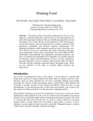
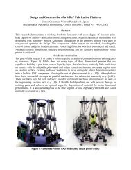
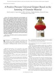
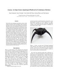
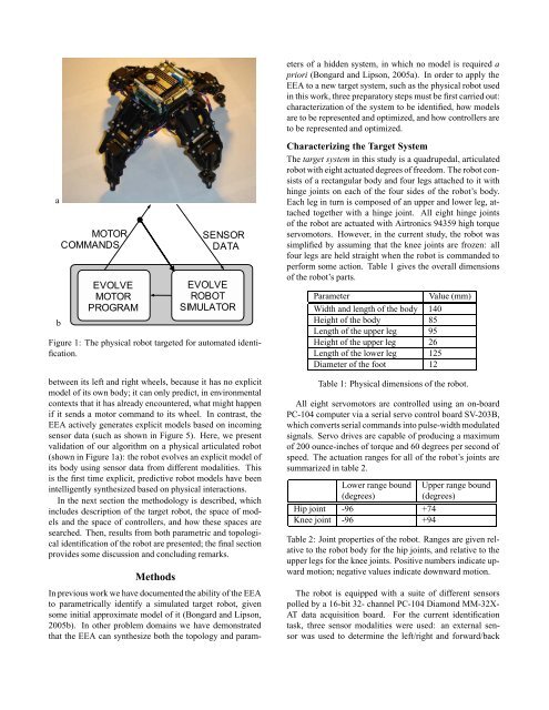
Figure 1: The physical robot targeted for automated identification.<br />
between its left and right wheels, because it has no explicit<br />
model <strong>of</strong> its own body; it can only predict, in environmental<br />
contexts that it has already encountered, what might happen<br />
if it sends a motor command to its wheel. In contrast, the<br />
EEA actively generates explicit models based on incoming<br />
sensor data (such as shown in Figure 5). Here, we present<br />
validation <strong>of</strong> our algorithm on a physical articulated robot<br />
(shown in Figure 1a): the robot evolves an explicit model <strong>of</strong><br />
its body <strong>using</strong> sensor data from different modalities. This<br />
is the first time explicit, predictive robot models have been<br />
intelligently synthesized based on physical interactions.<br />
In the next section the methodology is described, which<br />
includes description <strong>of</strong> the target robot, the space <strong>of</strong> models<br />
and the space <strong>of</strong> controllers, and how these spaces are<br />
searched. Then, results from both parametric and topological<br />
identification <strong>of</strong> the robot are presented; the final section<br />
provides some discussion and concluding remarks.<br />
Methods<br />
In previous work we have documented the ability <strong>of</strong> the EEA<br />
to parametrically identify a simulated target robot, given<br />
some initial approximate model <strong>of</strong> it (Bongard and Lipson,<br />
2005b). In other problem domains we have demonstrated<br />
that the EEA can synthesize both the topology and param-<br />
eters <strong>of</strong> a hidden system, in which no model is required a<br />
priori (Bongard and Lipson, 2005a). In order to apply the<br />
EEA to a new target system, such as the physical robot used<br />
in this work, three preparatory steps must be first carried out:<br />
characterization <strong>of</strong> the system to be identified, how models<br />
are to be represented and optimized, and how controllers are<br />
to be represented and optimized.<br />
Characterizing the Target System<br />
The target system in this study is a quadrupedal, articulated<br />
robot with eight actuated degrees <strong>of</strong> freedom. The robot consists<br />
<strong>of</strong> a rectangular body and four legs attached to it with<br />
hinge joints on each <strong>of</strong> the four sides <strong>of</strong> the robot’s body.<br />
Each leg in turn is composed <strong>of</strong> an upper and lower leg, attached<br />
together with a hinge joint. All eight hinge joints<br />
<strong>of</strong> the robot are actuated with Airtronics 94359 high torque<br />
servomotors. However, in the current study, the robot was<br />
simplified by assuming that the knee joints are frozen: all<br />
four legs are held straight when the robot is commanded to<br />
perform some action. Table 1 gives the overall dimensions<br />
<strong>of</strong> the robot’s parts.<br />
Parameter Value (mm)<br />
Width and length <strong>of</strong> the body 140<br />
Height <strong>of</strong> the body 85<br />
Length <strong>of</strong> the upper leg 95<br />
Height <strong>of</strong> the upper leg 26<br />
Length <strong>of</strong> the lower leg 125<br />
Diameter <strong>of</strong> the foot 12<br />
Table 1: Physical dimensions <strong>of</strong> the robot.<br />
All eight servomotors are controlled <strong>using</strong> an on-board<br />
PC-104 computer via a serial servo control board SV-203B,<br />
which converts serial commands into pulse-width modulated<br />
signals. Servo drives are capable <strong>of</strong> producing a maximum<br />
<strong>of</strong> 200 ounce-inches <strong>of</strong> torque and 60 degrees per second <strong>of</strong><br />
speed. The actuation ranges for all <strong>of</strong> the robot’s joints are<br />
summarized in table 2.<br />
Lower range bound Upper range bound<br />
(degrees) (degrees)<br />
Hip joint -96 +74<br />
Knee joint -96 +94<br />
Table 2: Joint properties <strong>of</strong> the robot. Ranges are given relative<br />
to the robot body for the hip joints, and relative to the<br />
upper legs for the knee joints. Positive numbers indicate upward<br />
motion; negative values indicate downward motion.<br />
The robot is equipped with a suite <strong>of</strong> different sensors<br />
polled by a 16-bit 32- channel PC-104 Diamond MM-32X-<br />
AT data acquisition board. For the current identification<br />
task, three sensor modalities were used: an external sensor<br />
was used to determine the left/right and forward/back