

Klartext 54 - heidenhain - DR. JOHANNES HEIDENHAIN GmbH
Klartext 54 - heidenhain - DR. JOHANNES HEIDENHAIN GmbH
Klartext 54 - heidenhain - DR. JOHANNES HEIDENHAIN GmbH

Create successful ePaper yourself
Turn your PDF publications into a flip-book with our unique Google optimized e-Paper software.
<strong>Klartext</strong> <strong>54</strong> + 09/2011<br />
Now it’s the iTNC’s turn<br />
(interpolation turning option)<br />
Interpolation turning is a real alternative<br />
for certain tasks, such the machining of<br />
flanges or shoulders. Here are some of<br />
the advantages: alignment of a rotationally<br />
asymmetric workpiece for turning is<br />
not necessary, nor are any exotic special<br />
tools, setup times are reduced, and more.<br />
How does interpolation turning even<br />
work?<br />
In interpolation turning the cutting edge of<br />
the tool moves on a circle, with the cutting<br />
edge always oriented to the center of<br />
the circle. This way you can produce rotationally<br />
symmetric objects in any working<br />
plane.<br />
The new interpolation turning cycle<br />
290, which is suited for finishing, does it<br />
like this:<br />
■ The starting and end point of a rotationally<br />
symmetric shoulder is defined.<br />
■ The center of rotation is the tool location<br />
in the working plane at the time<br />
the cycle is called.<br />
■ The rotational surfaces can be inclined<br />
or rounded relative to each other.<br />
The machining strategy can be chosen<br />
flexibly: from the outside in or vice versa,<br />
and also from top to bottom or vice versa.<br />
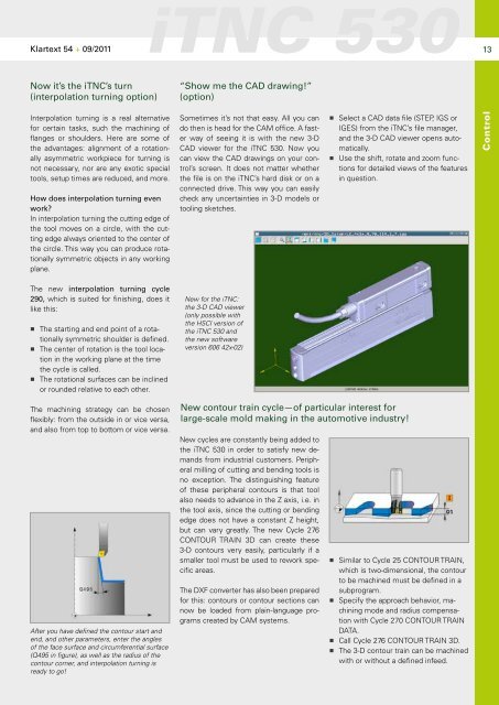
After you have defined the contour start and<br />
end, and other parameters, enter the angles<br />
of the face surface and circumferential surface<br />
(Q495 in figure), as well as the radius of the<br />
contour corner, and interpolation turning is<br />
ready to go!<br />
iTNC 530<br />
“Show me the CAD drawing!”<br />
(option)<br />
Sometimes it’s not that easy. All you can<br />
do then is head for the CAM office. A faster<br />
way of seeing it is with the new 3-D<br />
CAD viewer for the iTNC 530. Now you<br />
can view the CAD drawings on your control’s<br />
screen. It does not matter whether<br />
the file is on the iTNC’s hard disk or on a<br />
connected drive. This way you can easily<br />
check any uncertainties in 3-D models or<br />
tooling sketches.<br />
New for the iTNC:<br />
the 3-D CAD viewer<br />
(only possible with<br />
the HSCI version of<br />
the iTNC 530 and<br />
the new software<br />
version 606 42x-02)<br />
New contour train cycle—of particular interest for<br />
large-scale mold making in the automotive industry!<br />
New cycles are constantly being added to<br />
the iTNC 530 in order to satisfy new demands<br />
from industrial customers. Peripheral<br />
milling of cutting and bending tools is<br />
no exception. The distinguishing feature<br />
of these peripheral contours is that tool<br />
also needs to advance in the Z axis, i.e. in<br />
the tool axis, since the cutting or bending<br />
edge does not have a constant Z height,<br />
but can vary greatly. The new Cycle 276<br />
CONTOUR TRAIN 3D can create these<br />
3-D contours very easily, particularly if a<br />
smaller tool must be used to rework specific<br />
areas.<br />
The DXF converter has also been prepared<br />
for this: contours or contour sections can<br />
now be loaded from plain-language programs<br />
created by CAM systems.<br />
■ Select a CAD data file (STEP, IGS or<br />
IGES) from the iTNC’s file manager,<br />
and the 3-D CAD viewer opens automatically.<br />
■ Use the shift, rotate and zoom functions<br />
for detailed views of the features<br />
in question.<br />
■ Similar to Cycle 25 CONTOUR TRAIN,<br />
which is two-dimensional, the contour<br />
to be machined must be defined in a<br />
subprogram.<br />
■ Specify the approach behavior, machining<br />
mode and radius compensation<br />
with Cycle 270 CONTOUR TRAIN<br />
DATA.<br />
■ Call Cycle 276 CONTOUR TRAIN 3D.<br />
■ The 3-D contour train can be machined<br />
with or without a defined infeed.<br />
13<br />
Control


