AN10717 DMX512 communication using the LPC2000 - NXP ...
AN10717 DMX512 communication using the LPC2000 - NXP ...
AN10717 DMX512 communication using the LPC2000 - NXP ...

You also want an ePaper? Increase the reach of your titles
YUMPU automatically turns print PDFs into web optimized ePapers that Google loves.
<strong>AN10717</strong><br />
<strong>DMX512</strong> <strong>communication</strong> <strong>using</strong> <strong>the</strong> <strong>LPC2000</strong><br />
Rev. 01 — 1 July 2008 Application note<br />
Document information<br />
Info Content<br />
Keywords LPC2148, ARM7, <strong>DMX512</strong>, USB to <strong>DMX512</strong>, <strong>DMX512</strong> slave<br />
Abstract This application note demonstrates <strong>the</strong> use of a low cost ARM7 based<br />
<strong>NXP</strong> microcontroller as a <strong>DMX512</strong> transmitter and receiver.
<strong>NXP</strong> Semiconductors<br />
Revision history<br />
Rev Date Description<br />
01 20080701 Initial version.<br />
Contact information<br />
For additional information, please visit: http://www.nxp.com<br />
For sales office addresses, please send an email to: salesaddresses@nxp.com<br />
<strong>AN10717</strong><br />
<strong>DMX512</strong> <strong>communication</strong> <strong>using</strong> <strong>the</strong> <strong>LPC2000</strong><br />
<strong>AN10717</strong>_1 © <strong>NXP</strong> B.V. 2008. All rights reserved.<br />
Application note Rev. 01 — 1 July 2008 2 of 13
<strong>NXP</strong> Semiconductors<br />
1. Introduction<br />
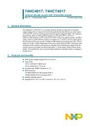
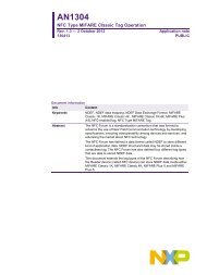
Fig 1. <strong>DMX512</strong> Packet<br />
<strong>AN10717</strong><br />
<strong>DMX512</strong> <strong>communication</strong> <strong>using</strong> <strong>the</strong> <strong>LPC2000</strong><br />
The <strong>DMX512</strong> standard describes a method of digital data transmission between<br />
controllers and controlled equipment. It is designed to carry repetitive control data from a<br />
single controller to one or more receivers.<br />
<strong>DMX512</strong> is a unidirectional asynchronous serial <strong>communication</strong> protocol. There’s no<br />
error checking or correction mechanism and <strong>the</strong>re’s no handshake between all receivers<br />
and <strong>the</strong> transmitter. This makes <strong>the</strong> protocol extremely simple, but also unsuitable for<br />
safety critical applications. The transmission rate is 250k Baud (11 bits data: 1 start bit, 8<br />
data bits and 2 stop bits) over an RS-485 interface. The physical interface (like cables<br />
and connectors) is not discussed in this application note.<br />
The transmitter is sending data in packets of up to 513 slots (see Fig 1). Each slot<br />
contains an 8-bit value, between 0 and 255. The first slot is a START Code, which<br />
defines <strong>the</strong> meaning of <strong>the</strong> information in <strong>the</strong> subsequent slots in <strong>the</strong> packet. The NULL<br />
Start Code is reserved for sending dimming data, where 0 means light off and 255<br />
represents a maximum light intensity.<br />
All receiver devices connected to <strong>the</strong> link choose one of <strong>the</strong> 512 slots (address selection)<br />
to extract <strong>the</strong> data for processing from each transmitted packet. The <strong>DMX512</strong>-A<br />
transmitter continuously repeats (at least once per second) <strong>the</strong> transmission of a packet<br />
as shown in Table 1.<br />
MBB MAB 2 stop bits<br />
Table 1. <strong>DMX512</strong> Timing Values<br />
Break Start code Slot 1 data Slot 512 data<br />
Description Min Typical Max Unit<br />
MBB – mark before break 0 - < 1.00 µsec / s<br />
Break 92 176 - µsec<br />
MAB – mark after break 12 - < 1.00 µsec / s<br />
Bit Time 3.92 4 4.08 µsec<br />
<strong>DMX512</strong> Packet 1204 - < 1.00 µsec / s<br />
<strong>AN10717</strong>_1 © <strong>NXP</strong> B.V. 2008. All rights reserved.<br />
Application note Rev. 01 — 1 July 2008 3 of 13
<strong>NXP</strong> Semiconductors<br />
2. <strong>DMX512</strong> transmitter<br />
USB<br />
6<br />
3 2<br />
5 4 1<br />
+<br />
5V<br />
10u<br />
<strong>AN10717</strong><br />
<strong>DMX512</strong> <strong>communication</strong> <strong>using</strong> <strong>the</strong> <strong>LPC2000</strong><br />
The DMX transmitter described in this application note is in fact a USB to <strong>DMX512</strong><br />
protocol converter. It’s a small board connected to <strong>the</strong> USB port of a PC running a simple<br />
GUI that can send a dimming value to one of 512 DMX slaves.<br />
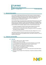
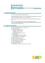
2.1 Hardware<br />
For <strong>the</strong> design an LPC2141 microcontroller is used (see Fig 2) because of its on-chip<br />
USB interface (used to communicate with a PC GUI). UART1 of <strong>the</strong> LPC2141 is used for<br />
<strong>the</strong> <strong>DMX512</strong> interface.<br />
LD1117S33<br />
IN OUT<br />
GND<br />
33e<br />
1K5<br />
3V3<br />
100n<br />
33e<br />
100n<br />
100n<br />
18p<br />
100n<br />
Fig 2. USB to <strong>DMX512</strong> demo board schematics<br />
3V3<br />
47K<br />
18p<br />
32<br />
28<br />
64<br />
24<br />
56<br />
52<br />
60<br />
20<br />
57<br />
16<br />
12<br />
8<br />
4<br />
48<br />
44<br />
40<br />
36<br />
11<br />
10<br />
49<br />
63<br />
23<br />
43<br />
51<br />
7<br />
6<br />
18<br />
25<br />
42<br />
50<br />
59<br />
P1.24<br />
P1.25<br />
P1.27<br />
P1.26<br />
P1.29<br />
P1.30<br />
P1.28<br />
P1.31<br />
RSTn<br />
P1.16<br />
P1.17<br />
P1.18<br />
P1.19<br />
P1.20<br />
P1.21<br />
P1.22<br />
P1.23<br />
D-<br />
D+<br />
Vbat<br />
Vref<br />
Vdd<br />
Vdd<br />
Vdd<br />
Vdda<br />
Vss<br />
Vss<br />
Vss<br />
Vss<br />
Vss<br />
Vssa<br />
LPC2141<br />
19<br />
P0.0<br />
21<br />
P0.1<br />
22<br />
P0.2<br />
26<br />
P0.3<br />
27<br />
P0.4<br />
29<br />
P0.5<br />
30<br />
P0.6<br />
31<br />
P0.7<br />
TXD1 / P0.8<br />
RXD1 / P0.9<br />
P0.10<br />
P0.11<br />
P0.12<br />
P0.13<br />
P0.14<br />
P0.15<br />
33<br />
34<br />
35<br />
37<br />
38<br />
39<br />
41<br />
45<br />
46<br />
P0.16<br />
47<br />
P0.17<br />
53<br />
P0.18<br />
54<br />
P0.19<br />
55<br />
P0.20<br />
1<br />
P0.21<br />
2<br />
P0.22<br />
58<br />
P0.23<br />
P0.25<br />
P0.28<br />
P0.29<br />
P0.30<br />
P0.31<br />
XTAL1<br />
XTAL2<br />
RTXC2<br />
RTXC1<br />
9<br />
13<br />
14<br />
15<br />
17<br />
62<br />
61<br />
5<br />
3<br />
5V<br />
47K<br />
22p<br />
12MHz<br />
100n<br />
3V3<br />
8<br />
VCC<br />
6<br />
1<br />
DO/RI<br />
7<br />
2<br />
RO DO/RI<br />
3<br />
RE<br />
4<br />
DE<br />
5<br />
DI GND<br />
22p<br />
DS75176<br />
<strong>DMX512</strong><br />
<strong>AN10717</strong>_1 © <strong>NXP</strong> B.V. 2008. All rights reserved.<br />
Application note Rev. 01 — 1 July 2008 4 of 13<br />
1<br />
2<br />
3
<strong>NXP</strong> Semiconductors<br />
2.2 Software<br />
<strong>AN10717</strong><br />
<strong>DMX512</strong> <strong>communication</strong> <strong>using</strong> <strong>the</strong> <strong>LPC2000</strong><br />
The example software is written in C language and compiled <strong>using</strong> Keil’s uVision (ARM7<br />
RealView, V3.1) free demo compiler. It performs following main tasks:<br />
2.2.1 main.c<br />
• Initialization: for LPC2141 configuration <strong>the</strong> standard startup code from Keil was<br />
used and set as CCLK = PCLK = 60 MHz<br />
• USB (HID class) interface for receiving slave number and dimming data. The USB<br />
modules from Keil’s HID example were used (not listed in this application note)<br />
• Use Timer 1 to generate a system-interrupt every 10 milliseconds and a timing event<br />
every 200 milliseconds (see timer1.c module listed below)<br />
• Sending of a <strong>DMX512</strong> packet every 200 milliseconds. This part consists of three<br />
modules (main.c – dmx.c – uart1.c), all listed below<br />
1 #include // LPC214x definitions<br />
2<br />
3 void SetOutReport(unsigned char *rep) // OutReport received from USB host<br />
4 {<br />
5 unsigned short i;<br />
6<br />
7 i = (rep[0] * 100) + rep[1]; // First 2 bytes are slave nr: 1-512<br />
8 DMX_buf[i] = rep[2]; // Third byte is dim value<br />
9 }<br />
10<br />
11 int main (void)<br />
12 {<br />
13 USB_Init(); // USB Initialization<br />
14 USB_Connect(TRUE); // USB Connect<br />
15 DMX_Init();<br />
16 T1_Init();<br />
17<br />
18 while(1)<br />
19 {<br />
20 if (f_200ms) // every 200 msec . . .<br />
21 {<br />
22 f_200ms = 0;<br />
23 DMX_SendPacket(); // <strong>DMX512</strong> send data to slaves<br />
24 }<br />
25 }<br />
26 }<br />
2.2.2 timer1.c<br />
1 #include <br />
2<br />
3 char f_10ms = 0;<br />
4 char f_200ms = 0;<br />
5<br />
6 __irq void T1_Isr(void) // Timer 1 ISR every 10 msec<br />
7 {<br />
8 static unsigned char cnt = 0;<br />
9<br />
10 f_10ms = 1; // toggles every 10 mseconds<br />
11<br />
12 if (++cnt > 20)<br />
<strong>AN10717</strong>_1 © <strong>NXP</strong> B.V. 2008. All rights reserved.<br />
Application note Rev. 01 — 1 July 2008 5 of 13
<strong>NXP</strong> Semiconductors<br />
2.2.3 dmx.c<br />
<strong>AN10717</strong><br />
<strong>DMX512</strong> <strong>communication</strong> <strong>using</strong> <strong>the</strong> <strong>LPC2000</strong><br />
13 {<br />
14 cnt = 0;<br />
15 f_200ms = 1; // toggles every 200 mseconds<br />
16 }<br />
17 T1IR = 0x01; // reset interrupt flag<br />
18 VICVectAddr = 0; // reset VIC<br />
19 }<br />
20<br />
21 void T1_Init(void)<br />
22 {<br />
23 VICVectAddr2 = (unsigned int) &T1_Isr;<br />
24 VICVectCntl2 = 0x25; // Channel2 on Source#5 ... enabled<br />
25 VICIntEnable |= 0x20; // Channel#5 is <strong>the</strong> Timer 1<br />
26<br />
27 T1MR0 = 600000; // = 10 msec / 16,67 nsec<br />
28 T1MCR = 3; // Interrupt on MR0, reset TC on match<br />
29 T1TC = 0; // reset Timer counter<br />
30 T1TCR = 1; // enable Timer<br />
31 }<br />
1 #include <br />
2<br />
3 unsigned char DMX_buf[513];<br />
4<br />
5 void DMX_SendPacket(void)<br />
6 {<br />
7 T0TC = 0; // reset Timer counter<br />
8 T0IR = 0x01; // reset interrupt flag<br />
9 T0MR0 = 92; // set match to 92 us<br />
10 U1LCR = 0x47; // 'break'<br />
11 T0TCR = 1; // start timer 0<br />
12 while ((T0IR & 0x01) == 0); // wait for timer match<br />
13<br />
14 T0TC = 0; // reset Timer counter<br />
15 T0IR = 0x01; // reset interrupt flag<br />
16 T0MR0 = 12; // set match to 12 us<br />
17 U1LCR = 7; // 'mark'<br />
18 T0TCR = 1; // start timer 0<br />
19 while ((T0IR & 0x01) == 0); // wait for timer match<br />
20<br />
21 UART1_Send(DMX_buf,513); // send data packet to slaves<br />
22 }<br />
23<br />
24 void DMX_Init(void)<br />
25 {<br />
26 int i;<br />
27<br />
28 for (i = 0; i < 513; i++) DMX_buf[i] = 0;<br />
29<br />
30 IODIR0 |= 0x00000080; // P0.7 = DS75176 enable<br />
31 IOSET0 |= 0x00000080; // Tx enable high active<br />
32 UART1_Init(250000);<br />
33 T0PR = 60; // 60, timer runs at 60 MHz / 60 = 1 MHz<br />
34 T0MCR = 7; // Int on MR0, reset and stop <strong>the</strong> timer<br />
35 }<br />
<strong>AN10717</strong>_1 © <strong>NXP</strong> B.V. 2008. All rights reserved.<br />
Application note Rev. 01 — 1 July 2008 6 of 13
<strong>NXP</strong> Semiconductors<br />
2.2.4 uart1.c<br />
<strong>AN10717</strong><br />
<strong>DMX512</strong> <strong>communication</strong> <strong>using</strong> <strong>the</strong> <strong>LPC2000</strong><br />
1 #include <br />
2<br />
3 #define Fosc 12000000<br />
4 #define Fpclk 60000000<br />
5<br />
6 unsigned int txin; // Next In Index<br />
7 unsigned int txout; // Next Out Index<br />
8 unsigned char *txbuf; // pointer to Tx buffer<br />
9<br />
10 __irq void U1_Isr(void)<br />
11 {<br />
12 char i = 16;<br />
13<br />
14 if ((U1IIR & 0x0F) == 2) // THRE Interrupt ?<br />
15 {<br />
16 while (i && txout)<br />
17 {<br />
18 U1THR = txbuf[txin++];<br />
19 txout --;<br />
20 i --;<br />
21 }<br />
22 }<br />
23 VICVectAddr = 0; // Acknowledge Interrupt<br />
24 }<br />
25<br />
26 void UART1_Send(unsigned char *buf, unsigned int len)<br />
27 {<br />
28 char i = 16;<br />
29<br />
30 if (txout == 0) // previous message send ?<br />
31 {<br />
32 txbuf = buf; // copy buffer pointer<br />
33 txout = len;<br />
34 txin = 0;<br />
35 while (i && txout)<br />
36 {<br />
37 U1THR = txbuf[txin++];<br />
38 txout --;<br />
39 i --;<br />
40 }<br />
41 }<br />
42 }<br />
43<br />
44 void UART1_Init(unsigned int baudrate)<br />
45 {<br />
46 volatile char dummy;<br />
47 unsigned int brd = (Fpclk / (baudrate
<strong>NXP</strong> Semiconductors<br />
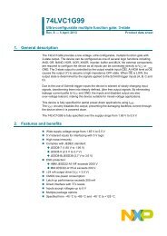
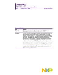
2.3 GUI<br />
Fig 3. <strong>DMX512</strong> - GUI<br />
<strong>AN10717</strong><br />
<strong>DMX512</strong> <strong>communication</strong> <strong>using</strong> <strong>the</strong> <strong>LPC2000</strong><br />
61 VICIntEnable |= 0x00000080; // Source #7 is UART1<br />
62<br />
63 dummy = U1IIR; // Read IrqID to get interrupts started<br />
64 U1IER = 2; // Enable UART1 THRE Interrupt<br />
65 }<br />
A Windows Ⓡ graphical user interface is available to control <strong>the</strong> USB to <strong>DMX512</strong> demo<br />
board (see Fig 3). The program is called “USB-DMX.EXE” and is developed in Microsoft<br />
Visual Basic 2008 Express, so it needs <strong>the</strong> Microsoft .NET framework at your PC.<br />
<strong>AN10717</strong>_1 © <strong>NXP</strong> B.V. 2008. All rights reserved.<br />
Application note Rev. 01 — 1 July 2008 8 of 13
<strong>NXP</strong> Semiconductors<br />
3. <strong>DMX512</strong> receiver<br />
USB<br />
6<br />
3 2<br />
5 4 1<br />
5V<br />
+<br />
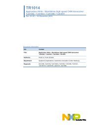
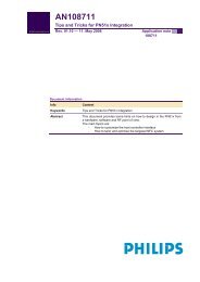
3.1 Hardware<br />
10u<br />
<strong>AN10717</strong><br />
<strong>DMX512</strong> <strong>communication</strong> <strong>using</strong> <strong>the</strong> <strong>LPC2000</strong><br />
For <strong>the</strong> <strong>DMX512</strong> receiver part an LPC2103 is used (see Fig 4). UART1 of <strong>the</strong> LPC2103<br />
is used for <strong>the</strong> <strong>DMX512</strong> interface. Received dimming data is output on ports P0.16 to<br />
P0.23 connected to a buffer and eight LEDs.<br />
LD1117S33<br />
IN OUT<br />
GND<br />
LD1117S18<br />
IN OUT<br />
GND<br />
3V3<br />
22p<br />
100n<br />
12MHz<br />
47K<br />
100n<br />
Fig 4. <strong>DMX512</strong> - Slave test application<br />
22p<br />
100n<br />
100n<br />
11<br />
12<br />
20<br />
25<br />
26<br />
6<br />
5<br />
4<br />
17<br />
40<br />
42<br />
27<br />
7<br />
19<br />
43<br />
31<br />
X1<br />
X2<br />
RTCX1<br />
RTCX2<br />
RTCK<br />
RST<br />
VDD(1V8)<br />
VBAT<br />
VDD(3V3)<br />
VDD(3V3)<br />
VDDA<br />
DBGSEL<br />
VSS<br />
VSS<br />
VSS<br />
VSSA<br />
LPC2103<br />
P0.0<br />
P0.1<br />
P0.2<br />
P0.3<br />
P0.4<br />
P0.5<br />
P0.6<br />
P0.7<br />
P0.8/TXD1<br />
P0.9/RXD1<br />
P0.10<br />
P0.11<br />
P0.16<br />
P0.17<br />
P0.18<br />
P0.19<br />
P0.20<br />
P0.21<br />
P0.22<br />
P0.23<br />
P0.24<br />
P0.25<br />
P0.26<br />
P0.27<br />
P0.28<br />
P0.29<br />
13<br />
14<br />
18<br />
21<br />
22<br />
23<br />
24<br />
28<br />
29<br />
30<br />
35<br />
36<br />
37<br />
P0.12<br />
41<br />
P0.13<br />
44<br />
P0.14<br />
45<br />
P0.15<br />
46<br />
47<br />
48<br />
1<br />
2<br />
3<br />
32<br />
33<br />
34<br />
38<br />
39<br />
8<br />
9<br />
10<br />
15<br />
P0.30<br />
16<br />
P0.31<br />
47K<br />
3V3<br />
5V<br />
100n<br />
8<br />
VCC<br />
6<br />
1<br />
DO/RI<br />
7<br />
2<br />
RO DO/RI<br />
3<br />
RE<br />
4<br />
DE<br />
5<br />
DI GND<br />
<strong>AN10717</strong>_1 © <strong>NXP</strong> B.V. 2008. All rights reserved.<br />
Application note Rev. 01 — 1 July 2008 9 of 13<br />
10<br />
DS75176<br />
1<br />
19<br />
OE1<br />
OE2<br />
2<br />
4<br />
A1<br />
6<br />
A2<br />
8<br />
A3<br />
11<br />
A4<br />
13<br />
A5<br />
15<br />
A6<br />
17<br />
A7<br />
A8<br />
GND<br />
74LVC244<br />
VCC<br />
20<br />
18<br />
Y1<br />
16<br />
Y2<br />
14<br />
Y3<br />
12<br />
Y4<br />
9<br />
Y5<br />
7<br />
Y6<br />
5<br />
Y7<br />
3<br />
Y8<br />
3V3<br />
120e<br />
8 x LED<br />
1<br />
2<br />
3<br />
<strong>DMX512</strong>
<strong>NXP</strong> Semiconductors<br />
3.2 Software<br />
<strong>AN10717</strong><br />
<strong>DMX512</strong> <strong>communication</strong> <strong>using</strong> <strong>the</strong> <strong>LPC2000</strong><br />
The receiver example software is written in C language and compiled <strong>using</strong> Keil’s uVision<br />
(ARM7 RealView, V3.1) free demo compiler. It performs following main tasks:<br />
3.2.1 main.c<br />
• Initialization: for LPC2103 configuration <strong>the</strong> standard startup code from Keil was<br />
used and set as CCLK = PCLK = 60 MHz<br />
• Use Timer 1 to generate a system-interrupt every 10 milliseconds and a timing event<br />
every 200 milliseconds (see timer1.c module listed below), used to output <strong>the</strong><br />
received slave data to 8 LEDs (see main.c module listed below)<br />
• Receiving of <strong>DMX512</strong> packets (uart1.c module listed below)<br />
1 #include // LPC2103 definitions<br />
2<br />
3 #define DMX_NR 368 // My own DMX slave numer<br />
4<br />
5 int main(void)<br />
6 {<br />
7 UART1_Init(250000);<br />
8 T1_Init();<br />
9<br />
10 IODIR |= 0x00FF0000; // LEDs at P0.16 - 23<br />
11 IOCLR |= 0x00FF0000; // turn LEDs off<br />
12<br />
13 while(1)<br />
14 {<br />
15 if (f_200ms)<br />
16 {<br />
17 f_200ms = 0;<br />
18 IOPIN = (IOPIN & 0xFF00FFFF) | (DMX_buf[DMX_NR] 20)<br />
13 {<br />
14 cnt = 0;<br />
15 f_200ms = 1; // toggles every 200 mseconds<br />
16 }<br />
17 T1IR = 0x01; // reset interrupt flag<br />
18 VICVectAddr = 0; // reset VIC<br />
19 }<br />
20<br />
<strong>AN10717</strong>_1 © <strong>NXP</strong> B.V. 2008. All rights reserved.<br />
Application note Rev. 01 — 1 July 2008 10 of 13
<strong>NXP</strong> Semiconductors<br />
<strong>AN10717</strong><br />
<strong>DMX512</strong> <strong>communication</strong> <strong>using</strong> <strong>the</strong> <strong>LPC2000</strong><br />
21 void T1_Init(void)<br />
22 {<br />
23 VICVectAddr1 = (unsigned int) &T1_Isr;<br />
24 VICVectCntl1 = 0x25; // Channel1 on Source#5 ... enabled<br />
25 VICIntEnable |= 0x20; // Channel#5 is <strong>the</strong> Timer 1<br />
26<br />
27 T1MR0 = 600000-1; // every 10 msec<br />
28 T1MCR = 3; // Interrupt on MR0, reset timer<br />
29 T1TC = 0; // reset Timer counter<br />
30 T1TCR = 1; // enable Timer<br />
31 }<br />
3.2.3 uart1.c<br />
1 #define Fpclk 60000000<br />
2<br />
3 unsigned int rxin = 0; // buffer index<br />
4 unsigned char DMX_buf[513], dummy;<br />
5<br />
6 __irq void U1_Isr(void)<br />
7 {<br />
8 static int iid;<br />
9<br />
10 while (((iid = U1IIR) & 1) == 0)<br />
11 {<br />
12 if ((iid & 0x0E) == 6) // Receive Line Status<br />
13 {<br />
14 U1LSR; U1RBR; // read LSR to clear <strong>the</strong> interrupt<br />
15 rxin = 0;<br />
16 }<br />
17 Else // Receive Data Available<br />
18 do<br />
19 {<br />
20 DMX_buf[rxin] = U1RBR;<br />
21 if (rxin < 513)<br />
22 rxin ++;<br />
23 } while (U1LSR & 1); // receive data ready<br />
24 }<br />
25 VICVectAddr = 0; // Acknowledge Interrupt<br />
26 }<br />
27<br />
28 void UART1_Init(unsigned int baudrate)<br />
29 {<br />
30 unsigned int brd = (Fpclk / (baudrate
<strong>NXP</strong> Semiconductors<br />
4. Legal information<br />
4.1 Definitions<br />
Draft — The document is a draft version only. The content is still under<br />
internal review and subject to formal approval, which may result in<br />
modifications or additions. <strong>NXP</strong> Semiconductors does not give any<br />
representations or warranties as to <strong>the</strong> accuracy or completeness of<br />
information included herein and shall have no liability for <strong>the</strong> consequences<br />
of use of such information.<br />
4.2 Disclaimers<br />
General — Information in this document is believed to be accurate and<br />
reliable. However, <strong>NXP</strong> Semiconductors does not give any representations<br />
or warranties, expressed or implied, as to <strong>the</strong> accuracy or completeness of<br />
such information and shall have no liability for <strong>the</strong> consequences of use of<br />
such information.<br />
Right to make changes — <strong>NXP</strong> Semiconductors reserves <strong>the</strong> right to make<br />
changes to information published in this document, including without<br />
limitation specifications and product descriptions, at any time and without<br />
notice. This document supersedes and replaces all information supplied prior<br />
to <strong>the</strong> publication hereof.<br />
<strong>AN10717</strong><br />
<strong>DMX512</strong> <strong>communication</strong> <strong>using</strong> <strong>the</strong> <strong>LPC2000</strong><br />
Suitability for use — <strong>NXP</strong> Semiconductors products are not designed,<br />
authorized or warranted to be suitable for use in medical, military, aircraft,<br />
space or life support equipment, nor in applications where failure or<br />
malfunction of a <strong>NXP</strong> Semiconductors product can reasonably be expected<br />
to result in personal injury, death or severe property or environmental<br />
damage. <strong>NXP</strong> Semiconductors accepts no liability for inclusion and/or use of<br />
<strong>NXP</strong> Semiconductors products in such equipment or applications and<br />
<strong>the</strong>refore such inclusion and/or use is for <strong>the</strong> customer’s own risk.<br />
Applications — Applications that are described herein for any of <strong>the</strong>se<br />
products are for illustrative purposes only. <strong>NXP</strong> Semiconductors makes no<br />
representation or warranty that such applications will be suitable for <strong>the</strong><br />
specified use without fur<strong>the</strong>r testing or modification.<br />
4.3 Trademarks<br />
Notice: All referenced brands, product names, service names and<br />
trademarks are property of <strong>the</strong>ir respective owners.<br />
<strong>AN10717</strong>_1 © <strong>NXP</strong> B.V. 2008. All rights reserved.<br />
Application note Rev. 01 — 1 July 2008 12 of 13
<strong>NXP</strong> Semiconductors<br />
5. Contents<br />
1. Introduction .........................................................3<br />
2. <strong>DMX512</strong> transmitter.............................................4<br />
2.1 Hardware...............................................................4<br />
2.2 Software ................................................................5<br />
2.2.1 main.c....................................................................5<br />
2.2.2 timer1.c .................................................................5<br />
2.2.3 dmx.c.....................................................................6<br />
2.2.4 uart1.c ...................................................................7<br />
2.3 GUI........................................................................8<br />
3. <strong>DMX512</strong> receiver..................................................9<br />
3.1 Hardware...............................................................9<br />
3.2 Software ..............................................................10<br />
3.2.1 main.c..................................................................10<br />
3.2.2 timer1.c ...............................................................10<br />
3.2.3 uart1.c .................................................................11<br />
4. Legal information ..............................................12<br />
4.1 Definitions............................................................12<br />
4.2 Disclaimers..........................................................12<br />
4.3 Trademarks .........................................................12<br />
5. Contents.............................................................13<br />
<strong>AN10717</strong><br />
<strong>DMX512</strong> <strong>communication</strong> <strong>using</strong> <strong>the</strong> <strong>LPC2000</strong><br />
Please be aware that important notices concerning this document and <strong>the</strong> product(s)<br />
described herein, have been included in <strong>the</strong> section 'Legal information'.<br />
© <strong>NXP</strong> B.V. 2008. All rights reserved.<br />
For more information, please visit: http://www.nxp.com<br />
For sales office addresses, email to: salesaddresses@nxp.com<br />
Date of release: 1 July 2008<br />
Document identifier: <strong>AN10717</strong>_1