Scout 37B operator and Parts Manual
Scout 37B operator and Parts Manual
Scout 37B operator and Parts Manual

You also want an ePaper? Increase the reach of your titles
YUMPU automatically turns print PDFs into web optimized ePapers that Google loves.
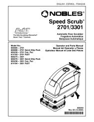
www.nobles.com<br />
R<br />
SCOUT <strong>37B</strong><br />
SWEEPER<br />
OPERATOR AND PARTS MANUAL<br />
608792<br />
Rev. 06 (12-2006)<br />
*608792*
All <strong>operator</strong>s <strong>and</strong> maintenance personnel MUST read <strong>and</strong> underst<strong>and</strong> this manual before<br />
operating or maintaining this equipment. Pay particular attention to cautions <strong>and</strong> warnings.<br />
If assistance is required, contact Customer Support at 1--800--553--8033.<br />
This manual covers all machine variations <strong>and</strong> st<strong>and</strong>ard options. The instruction portion<br />
of the manual consists of Specification, Operation, Maintenance, <strong>and</strong> Appendix sections.<br />
The parts portion consists of the machine <strong>Parts</strong>, Options, <strong>and</strong> Electrical Components.<br />
This machine will provide excellent service. However, the best results will be obtained at<br />
minimum costs if:<br />
D The machine is operated with reasonable care.<br />
D The machine is maintained regularly -- per the maintenance instructions<br />
provided.<br />
D The machine is maintained with manufacturer supplied or equivalent<br />
parts.<br />
<strong>Parts</strong> <strong>and</strong> supplies may be ordered by phone, mail, or fax. Before ordering parts or supplies,<br />
be sure to have your machine model number <strong>and</strong> serial number h<strong>and</strong>y. Fill out the<br />
data block below for future reference.<br />
Machine Serial Number --<br />
Date Of Installation --<br />
<strong>Manual</strong> Number --<br />
Revision Number: 05<br />
Published: 12--04<br />
MACHINE DATA<br />
Please fill out at time of installation.<br />
Tennant Company<br />
PO Box 1452<br />
Minneapolis, MN 554400<br />
Phone: (800)--533--8033 or (763) 513--2850<br />
www.tennantco.com<br />
CopyrightE 2001--2004 Tennant Company<br />
Nobles <strong>and</strong> <strong>Scout</strong> are United States trademarks of Tennant Company
The following symbols are used throughout this<br />
manual as indicated in their descriptions:<br />
WARNING: To warn of hazards or unsafe<br />
practices which could result in severe<br />
personal injury or death.<br />
FOR SAFETY: To identify actions which must<br />
be followed for safe operation of equipment.<br />
The following information signals potentially<br />
dangerous conditions to the <strong>operator</strong> or<br />
equipment. Read this manual carefully. Know<br />
when these conditions can exist. Locate all safety<br />
devices on the machine. Then, take necessary<br />
steps to train machine operating personnel.<br />
Report machine damage or faulty operation<br />
immediately. Do not use the machine if it is not in<br />
proper operating condition.<br />
WARNING: Batteries Emit Hydrogen Gas.<br />
Explosion Or Fire Can Result. Keep Sparks<br />
And Open Flame Away. Keep Covers Open<br />
When Charging.<br />
WARNING: Brush Throws Debris. Stop Motor<br />
Before Lifting Hopper.<br />
WARNING: Machine Moves When Motor Is<br />
Running. Stop Motor Before Leaving Machine.<br />
FOR SAFETY:<br />
1. Do Not Operate Machine:<br />
- Unless Trained And Authorized.<br />
- Unless Operation <strong>Manual</strong> Is Read<br />
And Understood.<br />
- In Flammable Or Explosive Areas<br />
Unless Designed For Use In Those<br />
Areas.<br />
- In Areas With Possible Falling Objects<br />
Unless Equipped With Overhead<br />
Guard.<br />
2. Before Starting Machine:<br />
- Make Sure All Safety Devices Are In<br />
Place And Operate Properly.<br />
3. When Using Machine:<br />
- Go Slow On Grades And Slippery<br />
Surfaces.<br />
- Use Care When Backing Machine.<br />
- Do Not Carry Riders On Machine.<br />
- Always Follow Safety And Traffic<br />
Rules.<br />
<strong>Scout</strong>t <strong>37B</strong> (3 -02)<br />
SAFETY PRECAUTIONS<br />
GENERAL INFORMATION<br />
4. Before Leaving Or Servicing Machine:<br />
- Stop On Level Surface.<br />
- Turn Off Machine And Remove Key.<br />
5. When Servicing Machine:<br />
- AvoidMoving<strong>Parts</strong>.DoNotWear<br />
Loose Jackets, Shirts, Or Sleeves<br />
When Working On Machine.<br />
- Block Machine Tires Before Jacking<br />
Machine Up.<br />
- Jack Machine Up At Designated<br />
Locations Only. Block Machine Up<br />
With Jack St<strong>and</strong>s.<br />
- Use Hoist Or Jack That Will Support<br />
The Weight Of The Machine.<br />
- Wear Eye And Ear Protection When<br />
Using Pressurized Air Or Water.<br />
- Disconnect Battery Connections<br />
Before Working On Machine.<br />
- Avoid Contact With Battery Acid.<br />
- Use Castex/Nobles Supplied Or<br />
Equivalent Replacement <strong>Parts</strong>.<br />
6. When Loading/Unloading Machine<br />
Onto/Off Truck Or Trailer:<br />
- Turn Off Machine.<br />
- Use Truck Or Trailer That Will Support<br />
The Weight Of The Machine.<br />
- Use Winch. Do Not Push The Machine<br />
Onto/Off The Truck Or Trailer Unless<br />
The Load Height Is 380 mm (15 in) Or<br />
Less From The Ground.<br />
- Block Machine Tires.<br />
- Tie Machine Down To Truck Or Trailer.<br />
1
GENERAL INFORMATION<br />
The following safety labels are mounted on the<br />
machine in the locations indicated. If these or any<br />
label becomes damaged or illegible, install a new<br />
label in its place.<br />
MACHINE CREEPING WARNING LABEL -<br />
LOCATED ON MACHINE HANDLE FRAME.<br />
FLYING DEBRIS WARNING LABEL -<br />
LOCATED ON TOP OF HOPPER.<br />
2<br />
FOR SAFETY LABEL - LOCATED ON<br />
MACHINE HANDLE FRAME.<br />
HAZARD CHARGING LABEL - LOCATED ON<br />
BATTERY COVER.<br />
01189<br />
<strong>Scout</strong>t <strong>37B</strong> (3 -01)
Page<br />
GENERAL INFORMATION .................. 1<br />
SAFETY PRECAUTIONS ................ 1<br />
CONTENTS ............................ 3<br />
SPECIFICATIONS ......................... 5<br />
MACHINE SPECIFICATIONS ............. 5<br />
POWER TYPE ....................... 5<br />
POWER TRAIN ...................... 5<br />
SUSPENSION SYSTEM .............. 5<br />
GENERAL MACHINE<br />
DIMENSIONS/CAPACITIES ........ 5<br />
MACHINE WEIGHTS ................. 5<br />
GENERAL MACHINE<br />
PERFORMANCE .................. 5<br />
MACHINE DIMENSIONS ................. 6<br />
OPERATION .............................. 7<br />
PREPARATION FOR OPERATION ........ 7<br />
OPERATION OF CONTROLS ............ 8<br />
MACHINE COMPONENTS ............... 8<br />
CLUTCH CONTROL HANDLE ......... 9<br />
MAIN BRUSH LIFT HANDLE .......... 9<br />
SIDE BRUSH ........................ 9<br />
MAIN BRUSH REMOVAL LEVER ...... 9<br />
BATTERY COVER ................... 10<br />
MASTER POWER SWITCH .......... 10<br />
MACHINE CIRCUIT BREAKER ....... 10<br />
CHARGER PANEL .................. 10<br />
HOUR METER ...................... 10<br />
MACHINE OPERATION ................. 11<br />
NORMAL SWEEPING OPERATION ... 11<br />
PRE-START CHECKLIST ............ 11<br />
TO START MACHINE ................ 11<br />
TO SWEEP ......................... 11<br />
TO DUMP HOPPER ................. 12<br />
POST OPERATION CHECKLIST --<br />
MOTOR OPERATING ............. 12<br />
TO STOP MACHINE ................. 12<br />
POST OPERATION CHECKLIST --<br />
MOTOR STOPPED ............... 12<br />
MACHINE TROUBLESHOOTING ........ 13<br />
MACHINE STORAGE ................... 14<br />
STORING MACHINE ................ 14<br />
MAINTENANCE .......................... 15<br />
RECOMMENDED FIRST 20-HOUR<br />
MACHINE INSPECTION ............. 15<br />
MAINTENANCE CHART ................ 16<br />
ELECTRICAL SYSTEM ................. 17<br />
BATTERIES ........................ 17<br />
BATTERY CHARGING ............... 17<br />
TO CHARGE BATTERIES ......... 18<br />
ELECTRICAL SCHEMATIC ........... 20<br />
<strong>Scout</strong>t <strong>37B</strong> (3 -02)<br />
CONTENTS<br />
GENERAL INFORMATION<br />
Page<br />
BRUSHES ............................. 21<br />
MAIN BRUSH ....................... 21<br />
TO REMOVE MAIN BRUSH ....... 21<br />
TO INSTALL MAIN BRUSH ........ 21<br />
TO CHECK AND ADJUST MAIN<br />
BRUSH PATTERN ............. 22<br />
SIDE BRUSH ....................... 23<br />
TO REMOVE SIDE BRUSH ........ 23<br />
TO INSTALL SIDE BRUSH ........ 23<br />
TO ADJUST SIDE BRUSH ......... 23<br />
DEBRIS HOPPER AND DUST FILTER .... 24<br />
DEBRIS HOPPER ................... 24<br />
TO EMPTY HOPPER ............. 24<br />
TO ADJUST HOPPER FLOOR<br />
CLEARANCE ................. 24<br />
REAR GUIDE WHEELS .............. 25<br />
TO ADJUST REAR GUIDE<br />
WHEELS ..................... 25<br />
HOPPER DUST FILTER .............. 25<br />
TO REMOVE DUST FILTER ....... 25<br />
TO INSTALL DUST FILTER ........ 26<br />
SKIRTS AND SEALS ................... 27<br />
SIDE DUST SKIRTS ................. 27<br />
TO ADJUST SIDE DUST SKIRTS .. 27<br />
TO REPLACE SIDE DUST<br />
SKIRTS ...................... 27<br />
HOPPER SIDE SEALS ............... 28<br />
TO REPLACE HOPPER SIDE<br />
SEALS ....................... 28<br />
REAR BRUSH SKIRT ................ 28<br />
TO REPLACE REAR BRUSH<br />
SKIRT ........................ 28<br />
BELTS AND CHAINS ................... 29<br />
FLAT PROPELLING BELT ............ 29<br />
TO CHECK AND ADJUST FLAT<br />
PROPELLING BELT ........... 29<br />
TO REPLACE FLAT PROPELLING<br />
BELT ......................... 29<br />
MOTOR DRIVE BELT ................ 30<br />
TO CHECK AND ADJUST MOTOR<br />
DRIVE BELT .................. 30<br />
TO REPLACE MOTOR<br />
DRIVE BELT ........................ 31<br />
BRUSH DRIVE BELT ................ 32<br />
TO REPLACE BRUSH<br />
DRIVE BELT .................. 32<br />
SIDE BRUSH DRIVE BELT ........... 33<br />
TO ADJUST SIDE BRUSH<br />
DRIVE BELT .................. 33<br />
TO REPLACE SIDE BRUSH<br />
DRIVE BELT .................. 33<br />
STATIC DRAG CHAIN ............... 33<br />
PUSHING AND TRANSPORTING<br />
THE MACHINE ...................... 34<br />
PUSHING THE MACHINE ............ 34<br />
TRANSPORTING THE MACHINE .....<br />
34<br />
3
GENERAL INFORMATION<br />
STANDARD MODEL PARTS<br />
Page<br />
............... 37<br />
HOW TO USE THIS MANUAL ........... 37<br />
IMPORTANT INFORMATION ......... 37<br />
FINDING A PART NUMBER .......... 37<br />
PLACING AN ORDER ............... 38<br />
Fig. 1 -- Recommended General<br />
Maintenance Items .......... 39<br />
Fig. 2 -- Replacement Brushes .......... 40<br />
Fig. 3 -- Main Frame <strong>and</strong> Charger Group . 42<br />
Fig. 4 -- H<strong>and</strong>le Group ................. 44<br />
Fig. 5 -- Hopper Assembly .............. 45<br />
Fig. 6 -- Brush Drive Group ............. 46<br />
Fig. 7 -- Motor <strong>and</strong> Wheel Drive Group ... 48<br />
Fig. 8 -- Filter Group ................... 50<br />
Fig. 9 -- Battery Group ................. 52<br />
Fig. 10 -- Wire Harnesses Group .......... 54<br />
Fig. 11 -- Vacuum Fan Group ............. 55<br />
Fig. 12 -- Label Kit ...................... 56<br />
Fig. 13 -- Cord Kit ....................... 57<br />
Fig. 14 -- Side Brush Group ..............<br />
58<br />
4<br />
<strong>Scout</strong>t <strong>37B</strong> (3 -01)
POWER TYPE<br />
Electric motor -- Nominal voltage 24 VDC,<br />
0.75 hp (0.56 kw) @ 2175 rpm, 29 A<br />
Batteries (2) -- 12 V, 530 CCA, 105Ah<br />
Battery charger -- 24 VDC, 15 A output<br />
115 VAC input<br />
Battery charger -- 24 VDC, 15 A, 115/230 VAC<br />
POWER TRAIN<br />
Propelling -- belt driven<br />
Main brush -- belt driven<br />
Side brush option -- belt driven<br />
SUSPENSION SYSTEM<br />
Front (2) -- 4 x 1.37 caster wheels<br />
Rear--8x2solidtire<br />
GENERAL MACHINE<br />
DIMENSIONS/CAPACITIES<br />
Length -- 52 in (1320 mm)<br />
Length with side brush -- 62 in (1575 mm)<br />
Width -- 32 in (815 mm)<br />
Widthwithsidebrush--34.5in(880mm)<br />
Height -- 40.25 in (1020 mm)<br />
Track -- 29.75 in (755 mm)<br />
Wheelbase -- 26.5 in (675 mm)<br />
Main brush diameter -- 8 in (205 mm)<br />
Main brush length -- 28.6 in (725 mm)<br />
Side brush diameter -- 16 in (405 mm)<br />
Sweeping path width -- 29 in (735 mm)<br />
Sweeping path width with side brush -- 37 in<br />
(940 mm)<br />
Hopper capacity -- 2.6 cu ft (0.07 m 3 )<br />
Dust filter area -- 49 sq ft (4.5 m 2 )<br />
<strong>Scout</strong>t <strong>37B</strong> (3 -01)<br />
MACHINE SPECIFICATIONS<br />
SPECIFICATIONS<br />
MACHINE WEIGHTS<br />
GVWR -- 435 lb (197 kg)<br />
St<strong>and</strong>ard net weight, dry -- 310 lb (141 kg)<br />
GENERAL MACHINE PERFORMANCE<br />
Maximum travel speed -- 3 mph (4.8 km/h)<br />
Turning radius -- 56 in (1420 mm)<br />
5
SPECIFICATIONS<br />
6<br />
40.25 in<br />
(1020 mm)<br />
MACHINE DIMENSIONS<br />
52 in<br />
(1320 mm)<br />
TOP VIEW<br />
26.5 in<br />
(675 mm)<br />
SIDE VIEW<br />
32 in<br />
(815 mm)<br />
FRONT VIEW<br />
<strong>Scout</strong>t <strong>37B</strong> (3 -01)
After uncrating <strong>and</strong> before operating the machine:<br />
1. Check the machine for shipping damage.<br />
Report any damage to the carrier at once.<br />
2. Read this manual carefully before operating<br />
or servicing this machine.<br />
FOR SAFETY: Do Not Operate Machine,<br />
Unless Operation <strong>Manual</strong> Is Read And<br />
Understood.<br />
3. Install the batteries <strong>and</strong> battery cables if not<br />
already done:<br />
E<br />
A<br />
A. Place the batteries in the machine with<br />
the positive (+) posts toward the front<br />
of the machine.<br />
<strong>Scout</strong>t <strong>37B</strong> (3 -01)<br />
C<br />
BATTERY CABLE CONNECTIONS<br />
A. Cable “4”<br />
B. Cable “3”<br />
C. Cable “1”<br />
D. Brush Lift Lever Side Battery<br />
E. Vacuum Fan Side Battery<br />
F. Front of Machine<br />
PREPARATION FOR OPERATION<br />
F<br />
B<br />
D<br />
00099<br />
B. Connect the cable labeled “1” between<br />
the positive (+) post on the vacuum fan<br />
side battery <strong>and</strong> the negative (--) post<br />
on the brush lift lever side battery.<br />
OPERATION<br />
C. Connect the cable labeled “3” to the<br />
positive (+) post of the brush lift lever<br />
side battery.<br />
D. Connect the cable labeled “4” to the<br />
negative (--) post of the vacuum fan<br />
side battery.<br />
4. Check the state of charge of the batteries as<br />
described in BATTERIES in the<br />
MAINTENANCE section. Charge the<br />
batteries if necessary.<br />
WARNING: Batteries Emit Hydrogen Gas.<br />
Explosion Or Fire Can Result. Keep Sparks<br />
And Open Flame Away. Keep Covers Open<br />
When Charging.<br />
5. Install the brushes as described in<br />
BRUSHES in the MAINTENANCE section.<br />
6. Connect the batteries-to-machine connector.<br />
B<br />
02669<br />
CONNECTING BATTERIES -TO -MACHINE<br />
CONNECTOR<br />
A<br />
A. Batteries Connector<br />
B. Machine Connector<br />
7. Check the brush pattern(s) as described in<br />
BRUSHES in the MAINTENANCE section.<br />
7
OPERATION<br />
8<br />
J<br />
I<br />
E<br />
OPERATION OF CONTROLS<br />
K<br />
F<br />
G<br />
D<br />
L<br />
H<br />
C<br />
MACHINE COMPONENTS<br />
A. Clutch Control H<strong>and</strong>le H. Dust Filter Enclosure<br />
B. Main Brush Lift H<strong>and</strong>le I. Master Power Switch<br />
C. Hopper J. 15 Amp Resetable Circuit Breaker<br />
D. Side Brush K. Hour Meter<br />
E. Side Brush Arm L. Machine Circuit Breaker<br />
F. Main Brush Removal Lever<br />
G. Battery Cover<br />
A<br />
B<br />
02666<br />
01189<br />
<strong>Scout</strong>t <strong>37B</strong> (6 -03)
CLUTCH CONTROL HANDLE<br />
The clutch control h<strong>and</strong>le operates a cable which<br />
controls the drive belt idler. To propel the machine<br />
forward, press the control h<strong>and</strong>le -- engaging the<br />
drive belt. To stop the machine, release the<br />
control h<strong>and</strong>le -- disengaging the drive belt.<br />
<strong>Scout</strong>t <strong>37B</strong> (3 -01)<br />
CLUTCH CONTROL HANDLE<br />
MAIN BRUSH LIFT HANDLE<br />
The main brush lift h<strong>and</strong>le operates a linkage<br />
which controls the height of the main brush.<br />
06249<br />
To lower the main brush, pull the h<strong>and</strong>le up, back,<br />
<strong>and</strong> release into the “lower” position.<br />
To raise the main brush, pull the h<strong>and</strong>le up <strong>and</strong><br />
forward into the “raise” position.<br />
MAIN BRUSH LIFT HANDLE<br />
01192<br />
OPERATION<br />
SIDE BRUSH<br />
The side brush option gives the machine the<br />
added flexibility of sweeping along walls <strong>and</strong><br />
under edges of tables, desks, etc. It is belt driven.<br />
To lower the side brush <strong>and</strong> start brush rotation,<br />
pull the side brush arm up, forward <strong>and</strong> down into<br />
the “operating” position -- this engages the drive<br />
belt.<br />
To raise the side brush <strong>and</strong> stop rotation, pull the<br />
side brush arm up <strong>and</strong> back into the “raised”<br />
position -- this disengages the drive belt.<br />
RAISING SIDE BRUSH<br />
MAIN BRUSH REMOVAL LEVER<br />
The main brush removal lever controls the main<br />
brush spring arm idler plug position. The spring<br />
arm secures the main brush in the idler plug. To<br />
remove the main brush, lift <strong>and</strong> pull the lever<br />
away from the machine. This disengages the<br />
main brush idler plug from the main brush.<br />
01195<br />
To install <strong>and</strong> secure the main brush in the<br />
machine, align the brush slots <strong>and</strong> idler keys <strong>and</strong><br />
swing the lever toward the machine, locking it on<br />
the machine frame. See MAIN BRUSH in the<br />
MAINTENANCE section.<br />
MAIN BRUSH REMOVAL LEVER<br />
01193<br />
9
OPERATION<br />
BATTERY COVER<br />
The battery cover covers the batteries <strong>and</strong> other<br />
electrical components. To tilt the battery cover<br />
forward, push the sides of the cover in. To remove<br />
or reinstall the battery cover, first remove the<br />
hopper. The front of the battery cover has hooks<br />
which are inserted in slots in the machine frame.<br />
Always have the battery cover in place when<br />
operating the machine. Always open the battery<br />
cover when charging the machine batteries.<br />
WARNING: Batteries Emit Hydrogen Gas.<br />
Explosion Or Fire Can Result. Keep Sparks<br />
And Open Flame Away. Keep Covers Open<br />
When Charging.<br />
10<br />
REMOVING BATTERY COVER<br />
01194<br />
MASTER POWER SWITCH<br />
The master power switch controls the machine<br />
motor. To start the motor, turn the key clockwise<br />
into the “on” position. To stop the motor turn the<br />
key counterclockwise into the “off” position. Do<br />
not leave the machine unattended when the motor<br />
is operating.<br />
WARNING: Machine Moves When Motor Is<br />
Running. Stop Motor Before Leaving Machine.<br />
MACHINE CIRCUIT BREAKER<br />
The machine circuit breaker provides the machine<br />
electrical overload protection, excluding the filter<br />
shaker motor. It is a 50 A circuit breaker. In the<br />
event of a circuit overload, the circuit breaker will<br />
trip. To reset the circuit breaker, push the reset<br />
button in. If the overload which caused the circuit<br />
breaker to trip is still present in the circuit, the<br />
circuit breaker will continue to stop current flow<br />
until the overload is corrected.<br />
NOTE: A 15 AMP Circuit Breaker provides<br />
additional electrical overload protection in the<br />
event of a short circuit. Reset by pushing in<br />
button.<br />
CHARGER PANEL<br />
The charger panel indicates battery charging<br />
status. The panel is located next to the vacuum<br />
fan housing. The panel shows the status of<br />
charging after the charger has been plugged into<br />
a wall outlet.<br />
The panel also has an interrupt switch to be used<br />
if the charging cycle needs to be stopped.<br />
NOTE: If the charge cycle has to be stopped,<br />
press the interrupt switch while unplugging the<br />
charger.<br />
A<br />
CHARGER PANEL<br />
A. Interrupt Switch<br />
HOUR METER<br />
The hour meter records the number of hours the<br />
machine has been operated. This information is<br />
useful in determining when to service the<br />
machine.<br />
06898<br />
<strong>Scout</strong>t <strong>37B</strong> (3 -01)
NORMAL SWEEPING OPERATION<br />
A normal sweeping operation consists of seven<br />
typical operations: pre-start checklist, starting<br />
machine, sweeping, dumping hopper, post<br />
operation checklist -- motor operating, stopping<br />
machine, <strong>and</strong> post operation checklist -- motor<br />
stopped.<br />
THE PRE-START CHECKLIST lists things to<br />
check before starting the machine.<br />
TO START MACHINE lists the steps required to<br />
start the machine.<br />
TO SWEEP lists things to keep in mind before<br />
<strong>and</strong> during the sweeping operation.<br />
TO DUMP HOPPER lists the steps required to<br />
dump the hopper.<br />
POST OPERATION CHECKLIST -- Motor<br />
Operating lists things to check before stopping the<br />
machine motor.<br />
TO STOP MACHINE lists the steps required to<br />
stop the machine.<br />
POST OPERATION CHECKLIST -- Motor<br />
Stopped lists things to check after stopping the<br />
machine motor.<br />
PRE-START CHECKLIST<br />
Check under machine for leak spots.<br />
Check battery charge level.<br />
Check controls for proper operation.<br />
Check service records to determine service<br />
requirements.<br />
FOR SAFETY: Before Starting Machine, Make<br />
Sure All Safety Devices Are In Place And<br />
Operate Properly.<br />
<strong>Scout</strong>t <strong>37B</strong> (3 -01)<br />
MACHINE OPERATION<br />
OPERATION<br />
TO START MACHINE<br />
NOTE: Before starting machine, perform the<br />
pre-start checks.<br />
1. Place the master power switch in the “on”<br />
position.<br />
2. Drive the machine to the area to be cleaned.<br />
TO SWEEP<br />
Plan the sweeping in advance. Try to arrange long<br />
runs with minimum stopping <strong>and</strong> starting. Sweep<br />
debris from very narrow aisles into main aisles<br />
ahead of time. Do an entire floor or section at one<br />
time. Overlap brush paths.<br />
Pick up oversize debris before sweeping. Flatten<br />
or remove bulky cartons from aisles before<br />
sweeping. Pick up pieces of wire, twine, string,<br />
etc., which could become entangled in brush or<br />
brush plugs.<br />
Press the clutch h<strong>and</strong>le to place the machine in<br />
motion. Release the clutch h<strong>and</strong>le for easier<br />
turning. Sweep as straight a path as possible.<br />
Avoid bumping into posts or scraping the sides of<br />
the sweeper. Empty the debris hopper when it<br />
becomes full.<br />
1. Place the main brush lift h<strong>and</strong>le in the<br />
“lower” position.<br />
2. Pull the side brush arm up, forward <strong>and</strong><br />
down into the “operating” position if present.<br />
3. Sweep as required.<br />
NOTE: Do not allow the machine to remain<br />
stationary with machine operating <strong>and</strong> the main<br />
brush in the “lower” position as it may cause wear<br />
marks on the floor.<br />
11
OPERATION<br />
TO DUMP HOPPER<br />
1. Stop the motor.<br />
WARNING: Brush Throws Debris. Stop Motor<br />
Before Lifting Hopper.<br />
12<br />
2. Grasp the hopper h<strong>and</strong>les with both h<strong>and</strong>s.<br />
3. Lift <strong>and</strong> swing the hopper upward to remove<br />
the hopper from the machine.<br />
REMOVING HOPPER<br />
4. Dump the debris out of the hopper into<br />
suitable refuse container.<br />
5. Tip the hopper down <strong>and</strong> slide it into place<br />
on the machine.<br />
01196<br />
POST OPERATION CHECKLIST -- MOTOR<br />
OPERATING<br />
Check brush patterns for width <strong>and</strong> evenness.<br />
TO STOP MACHINE<br />
1. When finished sweeping, place the main<br />
brush lift h<strong>and</strong>le <strong>and</strong> the side brush arm in<br />
the “raise” position.<br />
FOR SAFETY: Before Leaving Or Servicing<br />
Machine; Stop On Level Surface, And Turn Off<br />
Machine And Remove Key.<br />
2. Stop the motor.<br />
POST OPERATION CHECKLIST -- MOTOR<br />
STOPPED<br />
Check the batteries state of charge. Charge if<br />
needed.<br />
Check skirts for damage, wear, <strong>and</strong> adjustment.<br />
Check for wire or string tangled on brushes.<br />
<strong>Scout</strong>t <strong>37B</strong> (3 -88)
MACHINE TROUBLESHOOTING<br />
<strong>Scout</strong>t <strong>37B</strong> (3 -01)<br />
OPERATION<br />
Problem Cause Remedy<br />
Poor sweeping performance Main brush worn out Replace main brush<br />
Main Brush not properly adjusted Adjust main brush lift h<strong>and</strong>le to<br />
obtain correct brush pattern<br />
Main Brush not level with floor Adjust brush pattern<br />
Hopper full Empty hopper<br />
Dust filter clogged Remove <strong>and</strong> clean dust filter<br />
Brush jammed with debris Remove debris<br />
Hopper lip or dust skirt not<br />
properly adjusted<br />
Adjust hopper lip or dust skirt<br />
Brush drive belts slipping or<br />
broken<br />
Adjust or replace belts<br />
Dusting Dust filter clogged Remove <strong>and</strong> clean filter<br />
Filter not seated correctly against<br />
its seals<br />
Remove <strong>and</strong> re--install filter<br />
Dust filter damaged Replace dust filter<br />
Hopper full Empty hopper<br />
Clogged ducts Clean ducts<br />
Ducts not engaging seals or seals<br />
damaged<br />
Adjust or replace seals<br />
Dust skirts not properly adjusted<br />
or are damaged<br />
Adjust or replace dust skirts<br />
Vacuum fan not operating Fan drive sheave or impeller key<br />
is broken. Check drive belt<br />
Brush pattern not even Main brush not lowering evenly<br />
due to debris jam<br />
Remove main brush <strong>and</strong> debris<br />
Bail arm not level Adjust arm position<br />
Main brush spring arm may be out<br />
of adjustment<br />
Adjust arm position<br />
Main brush not seated correctly<br />
on drive cups<br />
Remove <strong>and</strong> re--install main brush<br />
Machine will not travel Flat belt broken Replace belt<br />
Oil on flat belt or shaft Clean belt <strong>and</strong> sheaves<br />
Clutch shaft arm loose or out of<br />
adjustment<br />
Adjust arm<br />
Clutch cable broken or out of<br />
adjustment<br />
Replace or adjust cable<br />
Rear drive wheel jammed Free wheel<br />
Motor drive belt broken or slipping Replace or adjust belt<br />
Excessive belt wear or Belt is over--tensioned or<br />
Adjust belt tension<br />
breakage<br />
under--tensioned, causing<br />
slippage<br />
Belt sheaves have moved out of<br />
adjustment<br />
Align sheaves<br />
Belt or sheaves have dirt or oil on<br />
them<br />
Clean sheaves <strong>and</strong> belt<br />
13
OPERATION<br />
STORING MACHINE<br />
When storing the machine for extended periods of<br />
time, the following procedures must be followed to<br />
lessen the chance of rust, sludge, <strong>and</strong> other<br />
deposits from forming:<br />
14<br />
1. Place the main brush, <strong>and</strong> side brush if so<br />
equipped, in the “raise” position.<br />
2. Empty <strong>and</strong> clean the debris hopper.<br />
3. Charge the machine batteries.<br />
4. Disconnect the batteries-to-machine battery<br />
connector.<br />
MACHINE STORAGE<br />
<strong>Scout</strong>t <strong>37B</strong> (3 -01)
<strong>Scout</strong>t <strong>37B</strong> (3 -01)<br />
RECOMMENDED FIRST 20-HOUR MACHINE INSPECTION<br />
After the first 20 hours of operation, perform the<br />
following procedures:<br />
1. Check the specific gravity of the batteries.<br />
2. Check the battery cable connections.<br />
3. Check the floor skirts to floor clearance.<br />
4. Check the main brush <strong>and</strong> side brush, if so<br />
equipped, brush patterns.<br />
MAINTENANCE<br />
15
MAINTENANCE<br />
16<br />
MAINTENANCE CHART<br />
7<br />
8<br />
4<br />
3<br />
10<br />
12<br />
11<br />
Interval Key Description Procedure<br />
9<br />
2<br />
3<br />
4<br />
5<br />
6<br />
7<br />
8<br />
1<br />
Lubricant/<br />
Fluid<br />
01189<br />
No. of<br />
Service<br />
Points<br />
Daily 11 Batteries Check electrolyte level -- 2<br />
6 Main brush Check for wear or damage -- 1<br />
10 Side brush Check for wear or damage -- 1<br />
1 Dust filter Rap clean -- 1<br />
20 Hours 11 Batteries Check specific gravity -- 2<br />
or Weekly 12 Battery cables Check for loose or corroded<br />
connections<br />
-- 3<br />
6 Main brush Rotate end-or-end <strong>and</strong> check<br />
brush pattern<br />
-- 1<br />
10 Side brush Check brush pattern -- 1<br />
80 Hours 11 Batteries Clean battery tops -- 2<br />
or 4 9 Debris hopper Check floor clearance adjustment -- 1<br />
Weeks 1 Dust filter Clean -- 1<br />
7 Side dust skirts Check for wear or damage <strong>and</strong><br />
adjustment<br />
-- 2<br />
8 Hopper side seals Check for wear or damage -- 2<br />
5 Rear brush skirt Check for wear or damage -- 1<br />
160 Hours<br />
or 8<br />
Weeks<br />
3 Drive belts Check for wear or damage <strong>and</strong><br />
adjustment<br />
-- 1<br />
2 Static drag chain Check for wear <strong>and</strong> floor contact -- 1<br />
4 Rear guide wheels Check floor clearance adjustment -- 2<br />
<strong>Scout</strong>t <strong>37B</strong> (3 -01)
BATTERIES<br />
The two 12-volt machine batteries provide all of<br />
the energy used by the machine. The st<strong>and</strong>ard<br />
batteries are rated at 530 CCA. They require<br />
regular maintenance to keep them operating their<br />
best.<br />
Do not allow batteries to remain in discharged<br />
condition for any length of time. Do not operate<br />
machine if batteries are in poor condition or<br />
discharged beyond 75%, specific gravity below<br />
1.170.<br />
Check the battery cables for loose connections on<br />
the battery terminals daily. Inspect the cables for<br />
corrosion or damage.<br />
Clean the top surface <strong>and</strong> the terminals of the<br />
batteries after every 80 hours of operation. Use a<br />
strong solution of baking soda <strong>and</strong> water. Brush<br />
the solution sparingly over the battery top,<br />
terminals, <strong>and</strong> cable clamps. Do not allow any<br />
baking soda solution to enter the battery. Use a<br />
wire brush to clean the terminal posts <strong>and</strong> the<br />
cable connectors. After cleaning, apply a coating<br />
of clear petroleum jelly to the terminals <strong>and</strong> the<br />
cable connectors. Keep the tops of the batteries<br />
clean <strong>and</strong> dry.<br />
Keep all metallic objects off the top of the<br />
batteries, as they may cause a short circuit.<br />
Replace worn or damaged wires.<br />
Check the electrolyte level in each battery cell<br />
before <strong>and</strong> after charging, <strong>and</strong> after every 50<br />
hours of operation. Do not charge the batteries<br />
unless the fluid is slightly above the battery plates.<br />
If needed, add just enough distilled water to cover<br />
the plates. Never add acid to the batteries. Do not<br />
overfill. Always keep the battery caps on, except<br />
when adding water or taking hydrometer readings.<br />
BATTERY ELECTROLYTE LEVEL<br />
<strong>Scout</strong>t <strong>37B</strong> (3 -01)<br />
ELECTRICAL SYSTEM<br />
MAINTENANCE<br />
Use a hydrometer to check the electrolyte specific<br />
gravity after every 20 hours of operation.<br />
If one or more battery cells tests lower than the<br />
other battery cells, (0.050 or more) the cell is<br />
damaged, shorted, or is about to fail.<br />
NOTE: Do not take readings immediately after<br />
adding water - if the water <strong>and</strong> acid are not<br />
thoroughly mixed, the readings may not be<br />
accurate. Check the hydrometer readings against<br />
this chart:<br />
SPECIFIC GRAVITY<br />
at 80_ F(27_C) BATTERY<br />
CONDITION<br />
1.260 -- 1.280 100% charged<br />
1.230 -- 1.250 75% charged<br />
1.200 -- 1.220 50% charged<br />
1.170 -- 1.190 25% charged<br />
1.110 -- 1.160 Discharged<br />
NOTE: If the readings are taken when the battery<br />
electrolyte is any temperature other than 80_ F<br />
(27_ C), the reading must be temperature<br />
corrected.<br />
To determine the corrected specific gravity<br />
reading when the temperature of the battery<br />
electrolyte is other than 80_ F(27_ C):<br />
Add to the specific gravity reading 0.004,<br />
4 points, for each 10_ F(6_ C) above 80_ F<br />
(27_ C).<br />
Subtract from the specific gravity reading<br />
0.004, 4 points for each 10_ F(6_ C) below<br />
80_ F(27_ C).<br />
BATTERY CHARGING<br />
The machine batteries are specifically made for<br />
this machine application. They are unique in that<br />
they hold their power for long periods of time, but<br />
they can only be recharged a certain number of<br />
times. To get the most life from the batteries,<br />
charge them when 75% of the battery power has<br />
been used, so the battery specific gravity is<br />
between 1.190 <strong>and</strong> 1.170.<br />
Do not charge the batteries for more than eight<br />
hours. If batteries are not fully discharged, reduce<br />
charging time proportionally.<br />
Do not expose the battery charger to water. Do<br />
not touch uninsulated battery terminals or<br />
unnecessarily expose any portion of your body to<br />
the batteries when making electrical connections.<br />
17
MAINTENANCE<br />
TO CHARGE BATTERIES<br />
1. Stop the machine on a flat, dry surface next<br />
to an electrical outlet.<br />
18<br />
2. Turn off the master power switch.<br />
FOR SAFETY: Before Leaving Or Servicing<br />
Machine; Stop On Level Surface, And Turn Off<br />
Machine And Remove Key.<br />
3. Lift the battery cover into the “open”<br />
position.<br />
WARNING: Batteries Emit Hydrogen Gas.<br />
Explosion Or Fire Can Result. Keep Sparks<br />
And Open Flame Away. Keep Covers Open<br />
When Charging.<br />
4. Check the water level in the batteries.<br />
CHECK ELECTROLYTE LEVEL<br />
If the water level is low, add just enough distilled<br />
water to cover the plates. DO NOT OVERFILL.<br />
The battery can overflow during charging due to<br />
expansion.<br />
BATTERY ELECTROLYTE LEVEL<br />
08247<br />
FOR SAFETY: When Servicing Machine, Avoid<br />
Contact With Battery Acid.<br />
5. Plug the battery charger into an AC wall<br />
outlet. The charger will go through a self<br />
diagnostic check. All the indicator lamps on<br />
the charger panel will flash showing the<br />
diagnostic check is in progress.<br />
NOTE:Ifthered no charge indicator lamp lights<br />
when the charger is plugged into a wall outlet, the<br />
charger can not charge the battery, meaning there<br />
is something wrong with the battery.<br />
When the lamps stop flashing, the red<br />
incomplete battery status indicator lamp<br />
lights. After a short delay, the yellow charger<br />
on indicator lamp lights showing the charger<br />
has turned on.<br />
A<br />
B C D E F<br />
CHARGER PANEL<br />
06898<br />
A. Interrupt Switch<br />
B. Red No Charge Indicator Lamp<br />
C. Yellow Charger On Indicator Lamp<br />
D. Red Incomplete Battery Status<br />
Indicator Lamp<br />
E. Yellow 80% Charge Indicator Lamp<br />
F. Green Complete Charge Indicator<br />
Lamp<br />
As the battery charges, the red incomplete<br />
battery status indicator lamp goes out <strong>and</strong><br />
the yellow 80% charge indicator lamp lights.<br />
Finally the yellow 80% charge indicator lamp<br />
goes out <strong>and</strong> the green complete charge<br />
indicator lamp lights showing the battery is<br />
completely charged. After a short time, the<br />
yellow charger on indicator lamp goes out<br />
showing the charger has turned off.<br />
The green complete charge indicator lamp<br />
will remain on until the charger is unplugged<br />
from the wall outlet.<br />
NOTE: If the charge cycle has to be stopped,<br />
press the interrupt switch while unplugging the<br />
charger from the wall outlet.<br />
<strong>Scout</strong>t <strong>37B</strong> (3 -01)
6. Unplug the charger from the wall outlet.<br />
7. Check the electrolyte level in each battery<br />
cell after charging. If needed, add distilled<br />
water to raise the electrolyte level to about<br />
12 mm (0.4 in) below the bottom of the sight<br />
tubes.<br />
8. Close the battery cover.<br />
<strong>Scout</strong>t <strong>37B</strong> (3 -02)<br />
MAINTENANCE<br />
19
MAINTENANCE<br />
20<br />
41/BLK<br />
42/BLU<br />
FEMALE<br />
4<br />
6<br />
40A/WHT<br />
3<br />
FEMALE<br />
MALE<br />
MALE<br />
42/BLU<br />
40A/WHT<br />
BLACK<br />
WHITE<br />
GREEN<br />
1<br />
VOLTAGE CONNECTIONS<br />
AC VOLTAGE CONNECT<br />
112 TO 125 1TO4&3TO6<br />
218 TO 240 3TO4<br />
40/WHT<br />
S.W.<br />
B2<br />
B1<br />
2<br />
A1<br />
A2<br />
1<br />
CONTROL PANEL<br />
40A/WHT<br />
42/BLU<br />
TRANSFORMER: 50 HZ<br />
WHITE<br />
43/YEL<br />
660VAC<br />
CAP.<br />
TRANSFORMER: 100VAC<br />
ELECTRICAL SCHEMATIC<br />
43/YEL<br />
TRANSFORMER: 60 HZ - 120VAC<br />
CB -5<br />
11<br />
1<br />
6<br />
13<br />
7<br />
43/YEL 44/BRN<br />
44/BRN<br />
2<br />
VFC 2200 3<br />
5<br />
4<br />
6<br />
CAPACITOR<br />
DC<br />
CB -4<br />
YELLOW<br />
WHITE<br />
BLUE<br />
CAPACITOR<br />
50 HZ WHITE TO BLUE<br />
60 HZ<br />
CYCLE PHASE<br />
STOP<br />
N.O.<br />
44/BRN<br />
CB -3<br />
WHITE TO YELLOW<br />
FEMALE<br />
MALE<br />
FEMALE<br />
DC<br />
11/RED<br />
12/V 12/V<br />
RED BLK BLK<br />
8/RED<br />
CB -1<br />
24/BLK<br />
50A<br />
CB -2<br />
7/RED 17/BLU<br />
28/ORA<br />
15A KEY S.W.<br />
DC<br />
9/BLK<br />
2/BLK<br />
DRIVE<br />
MTR<br />
16/BLK<br />
PM<br />
SEE BELOW<br />
M1<br />
27/ORA<br />
HM<br />
26/BLK<br />
25/BLK<br />
29/ORA 30/BLK<br />
VM<br />
06985<br />
<strong>Scout</strong>t <strong>37B</strong> (3 -01)
MAIN BRUSH<br />
The main brush is tubular <strong>and</strong> spans the width of<br />
the machine. It sweeps debris into the hopper. It<br />
should be inspected daily for wear or damage.<br />
Remove any string or wire found tangled on the<br />
main brush, main brush drive hub, or main brush<br />
idler hub.<br />
The main brush pattern should be checked after<br />
every 20 hours of operation. The main brush<br />
pattern should be approximately 1.5 in (40 mm)<br />
wide when sweeping hard floors <strong>and</strong> 0.5 in<br />
(15 mm) when sweeping carpeted floors. Check<br />
the main brush pattern only on hard floors with the<br />
main brush in the lowered position. Main brush<br />
pattern adjustments are made by rotating the<br />
main brush lift h<strong>and</strong>le. Use the carpet brush on<br />
carpets for better performance <strong>and</strong> brush life.<br />
Rotate the brush after every 20 hours of operation<br />
for maximum brush life. The main brush should be<br />
replaced when the remaining brush bristle<br />
measures 1.25 in (30 mm).<br />
TO REMOVE MAIN BRUSH<br />
1. Place the master power switch in the “off”<br />
position.<br />
FOR SAFETY: Before Leaving Or Servicing<br />
Machine; Stop On Level Surface, And Turn Off<br />
Machine And Remove Key.<br />
2. Disconnect the batteries-to-machine<br />
connector.<br />
3. Lift the hopper up <strong>and</strong> out of the machine.<br />
WARNING: Brush Throws Debris. Stop Motor<br />
Before Lifting Hopper.<br />
4. Pull the main brush removal lever away from<br />
the machine to disengage the main brush<br />
idler plug from the main brush.<br />
5. Grasp the main brush <strong>and</strong> pull it off the main<br />
brush drive plug <strong>and</strong> out of the main brush<br />
compartment.<br />
<strong>Scout</strong>t <strong>37B</strong> (3 -01)<br />
BRUSHES<br />
MAINTENANCE<br />
TO INSTALL MAIN BRUSH<br />
1. Pull the main brush removal lever away from<br />
the machine.<br />
2. Line up one of the slotted ends of the main<br />
brush with the drive plug drive keys.<br />
A<br />
A<br />
B<br />
MAIN BRUSH DRIVE SLOTS<br />
A. Main Brush<br />
B. Drive Slot<br />
B<br />
01207<br />
01208<br />
MAIN BRUSH DRIVE PLUG DRIVE KEYS<br />
A. Drive Plug<br />
B. Drive Key<br />
21
MAINTENANCE<br />
22<br />
3. Fit one end of the main brush over the main<br />
brush drive plug.<br />
INSTALLING MAIN BRUSH<br />
4. Position the other end of the main brush<br />
over the main brush idler plug.<br />
01209<br />
5. Push <strong>and</strong> lock the main brush removal lever<br />
into place on the machine frame to secure<br />
themainbrush.<br />
6. Check <strong>and</strong> adjust the main brush pattern as<br />
described in TO CHECK AND ADJUST<br />
MAIN BRUSH PATTERN.<br />
7. Reconnect the batteries-to-machine<br />
connector.<br />
TO CHECK AND ADJUST MAIN BRUSH<br />
PATTERN<br />
1. Place the machine over a hard floor.<br />
2. Place the master power switch in the “on”<br />
position.<br />
3. Place the main brush lift h<strong>and</strong>le in the<br />
“lower” position to lower the main brush to<br />
the floor for one minute while holding the<br />
machine in one place.<br />
4. Pull the main brush lift h<strong>and</strong>le up <strong>and</strong><br />
forwardtoraisethemainbrush.<br />
5. Move the machine away from the main<br />
brush polish mark.<br />
6. Place the master power switch in the “off”<br />
position.<br />
FOR SAFETY: Before Leaving Or Servicing<br />
Machine; Stop On Level Surface, And Turn Off<br />
Machine And Remove Key.<br />
7. Observe the width of the polish mark. The<br />
proper polish width is 1.5 in (40 mm) for<br />
hard floors <strong>and</strong> 0.5 in (15 mm) for carpet<br />
floors.<br />
A<br />
MAIN BRUSH PATTERN<br />
A. Main Brush Pattern<br />
B. Polish Width<br />
If the polish mark width is too wide, turn the main<br />
brush lift h<strong>and</strong>le clockwise to raise the brush.<br />
If the polish mark width is too narrow, turn the<br />
main brush lift h<strong>and</strong>le counterclockwise to lower<br />
the brush.<br />
If any adjustments are made, recheck the main<br />
brush pattern before resuming work with the<br />
machine.<br />
B<br />
00582<br />
<strong>Scout</strong>t <strong>37B</strong> (3 -01)
SIDE BRUSH<br />
The side brush sweeps debris from walls or curbs<br />
into the path of the main brush. It should be<br />
inspected daily for wear or damage. Remove any<br />
string or wire found tangled on the side brush or<br />
side brush drive hub.<br />
The side brush adjustment should be checked<br />
after every 20 hours of operation. The side brush<br />
is properly adjusted when, with the side brush arm<br />
in the “raised” position, there is approximately<br />
1 in (25 mm) of space between the floor <strong>and</strong> the<br />
side brush bristles.<br />
Side brush adjustments are made by mounting<br />
thesidebrushinadifferentoneofthefive<br />
mounting holes in the side brush drive shaft.<br />
The side brush should be replaced when the<br />
remaining brush bristle measures 1 in (25 mm) in<br />
length.<br />
TO REMOVE SIDE BRUSH<br />
1. Place the master power switch in the “off”<br />
position.<br />
FOR SAFETY: Before Leaving Or Servicing<br />
Machine; Stop On Level Surface, And Turn Off<br />
Machine And Remove Key.<br />
2. Pull the side brush arm up <strong>and</strong> back to raise<br />
thesidebrush.<br />
3. Remove the side brush retaining bolt or hair<br />
cotter pin.<br />
01027<br />
REMOVING SIDE BRUSH RETAINING BOLT<br />
4. Slide the side brush off the side brush drive<br />
shaft.<br />
<strong>Scout</strong>t <strong>37B</strong> (3 -01)<br />
MAINTENANCE<br />
TO INSTALL SIDE BRUSH<br />
1. Slide the side brush onto the side brush<br />
drive shaft.<br />
2. Fasten the side brush to the shaft with the<br />
retaining bolt or hair cotter pin.<br />
3. Check the side brush adjustment as<br />
described in TO ADJUST SIDE BRUSH.<br />
TO ADJUST SIDE BRUSH<br />
1. Place the master power switch in the “off”<br />
position.<br />
FOR SAFETY: Before Leaving Or Servicing<br />
Machine; Stop On Level Surface, And Turn Off<br />
Machine And Remove Key.<br />
2. Pull the side brush arm up <strong>and</strong> back to put<br />
the side brush in the “raised” position.<br />
3. Remove the side brush retaining bolt or hair<br />
cotter pin.<br />
4. Slide the side brush up or down on the shaft<br />
until there is approximately 1 in (25 mm) of<br />
space between the floor <strong>and</strong> the side brush<br />
bristles.<br />
ADJUSTING SIDE BRUSH HEIGHT<br />
01027<br />
5. Line up the side brush <strong>and</strong> drive shaft holes<br />
to allow the side brush to be nearest to the<br />
specified dimension.<br />
6. Secure the side brush to the drive shaft with<br />
the retaining bolt or hair cotter pin.<br />
23
MAINTENANCE<br />
DEBRIS HOPPER<br />
The debris hopper collects debris swept up by the<br />
main brush. It should be emptied after every work<br />
shift.<br />
The hopper floor clearance should be checked<br />
<strong>and</strong> adjusted, if necessary, after every 80 hours of<br />
operation.<br />
TO EMPTY HOPPER<br />
1. Place the master power switch in the “off”<br />
position.<br />
WARNING: Brush Throws Debris. Stop Motor<br />
Before Lifting Hopper.<br />
24<br />
2. Grasp the hopper h<strong>and</strong>les with both h<strong>and</strong>s.<br />
3..Lift <strong>and</strong> swing the hopper upward to remove<br />
the hopper from the machine.<br />
REMOVING HOPPER<br />
4. Dump the debris out of the hopper into<br />
suitable refuse container.<br />
5. Tip the hopper down <strong>and</strong> slide it into place<br />
on the machine.<br />
DEBRIS HOPPER AND DUST FILTER<br />
01196<br />
TO ADJUST HOPPER FLOOR CLEARANCE<br />
1. Empty the hopper<br />
2. Stop the machine on a smooth level floor.<br />
3. Place the master power switch in the “off”<br />
position.<br />
FOR SAFETY: Before Leaving Or Servicing<br />
Machine; Stop On Level Surface, And Turn Off<br />
Machine And Remove Key.<br />
4. Loosen the three hopper top seal retainer<br />
bolts on the hopper.<br />
HOPPER TOP SEAL RETAINER<br />
B<br />
A. Hopper Top Seal Retainer<br />
B. Retainer Bolt<br />
5. Place two 0.38 to 0.5 in (10 to 15 mm)<br />
blocks on the floor under the hopper wear<br />
plate.<br />
6. Slide the hopper top seal retainer up or<br />
down so that the retainer just touches the<br />
machine frame.<br />
7. Tighten the hopper top seal retainer bolts.<br />
8. Remove the blocks from under the hopper<br />
wear plate.<br />
A<br />
01210<br />
<strong>Scout</strong>t <strong>37B</strong> (3 -01)
REAR GUIDE WHEELS<br />
The rear guide wheels prevent the rear of the<br />
machine from tipping. They are located just<br />
behind the main brush shroud. Check the floor<br />
clearance after every 160 hours of operation.<br />
They should clear the floor by 0.38 in (10 mm).<br />
TO ADJUST REAR GUIDE WHEELS<br />
1. Place the master power switch in the “off”<br />
position.<br />
FOR SAFETY: Before Leaving Or Servicing<br />
Machine; Stop On Level Surface, And Turn Off<br />
Machine And Remove Key.<br />
2. Loosen the two bolts holding each of the<br />
rear guide wheels in place.<br />
3. Slide the guide wheels up or down so that<br />
they clear the floor by 0.38 in (10 mm).<br />
<strong>Scout</strong>t <strong>37B</strong> (3 -01)<br />
REAR GUIDE WHEEL<br />
4. Tighten the two bolts on each guide wheel.<br />
01211<br />
MAINTENANCE<br />
HOPPER DUST FILTER<br />
The hopper dust filter is located inside the dust<br />
filter compartment. The dust filter filters the air<br />
which is drawn up from the main brush<br />
compartment. Rap on the front filter housing with<br />
a fist daily to shake the excess dust from the filter.<br />
Clean the filter after every 3 hours of operation.<br />
Use one of the following methods to clean the<br />
dust filter:<br />
D Tapping -- Tap the filter gently on a flat<br />
surface with the dirty side down. Do not<br />
damage the edges of the filter element or<br />
the filter will not seat properly in the filter<br />
frame.<br />
D Air -- Blow compressed air, 40 psi (275 kPa)<br />
maximum, through the dust filter opposite<br />
the direction of the arrows.<br />
D Water -- Soak the dust filter in a water <strong>and</strong><br />
mild detergent solution. Rinse the dust filter<br />
until it is clean. The maximum water<br />
pressure allowable is 40 psi (275 kPa). Air<br />
dry the wet dust filter; do not use<br />
compressed air.<br />
NOTE: Be sure the dust filter is dry before<br />
reinstalling it in the machine.<br />
TO REMOVE DUST FILTER<br />
1. Place the master power switch in the “off”<br />
position.<br />
FOR SAFETY: Before Leaving Or Servicing<br />
Machine; Stop On Level Surface, And Turn Off<br />
Machine And Remove Key.<br />
2. Rap on the front filter housing with a fist to<br />
shake the excess dust from the dust filter.<br />
RAPPING FILTER HOUSING<br />
25
MAINTENANCE<br />
B<br />
A<br />
26<br />
3. Unlatch the two filter cover latches <strong>and</strong><br />
lower the rear filter cover.<br />
B<br />
LOWERING REAR FILTER COVER<br />
A. Rear Filter Cover<br />
B. Filter Cover Latch<br />
A<br />
01214<br />
4. Slide the filter retention bar up <strong>and</strong> out of the<br />
slotted retention brackets.<br />
REMOVING FILTER RETENTION BAR<br />
A. Filter Retention Bar<br />
B. Retention Bracket<br />
5. Push the filter retention spring upward <strong>and</strong><br />
slide the filter out of the filter compartment.<br />
01215<br />
TO INSTALL DUST FILTER<br />
1. Push the filter retention spring upward <strong>and</strong><br />
slide the filter into place on the filter base in<br />
the filter compartment.<br />
A<br />
B<br />
INSTALLING FILTER<br />
A. Filter<br />
B. Filter Housing<br />
NOTE: Make sure the arrows on the filter are<br />
pointing to the front of the machine.<br />
2. Release the filter retention spring.<br />
3. Slide the filter retention bar down into the<br />
slotted retention brackets.<br />
4. Lift the rear filter cover back into the<br />
“operating” position.<br />
5. Latch the two filter cover latches.<br />
02667<br />
<strong>Scout</strong>t <strong>37B</strong> (3 -01)
SIDE DUST SKIRTS<br />
A dust skirt is located on each side of the brush<br />
compartment. They control main brush dusting.<br />
The dust skirts should be inspected for wear or<br />
damage <strong>and</strong> adjustment after every 80 hours of<br />
operation.<br />
TO ADJUST SIDE DUST SKIRTS<br />
1. Place the master power switch in the “off”<br />
position.<br />
WARNING: Brush Throws Debris. Stop Motor<br />
Before Lifting Hopper.<br />
2. Grasp the hopper h<strong>and</strong>les; lift <strong>and</strong> swing the<br />
hopper up <strong>and</strong> out of the machine.<br />
3. Loosen the side dust skirts retaining bolts.<br />
B<br />
<strong>Scout</strong>t <strong>37B</strong> (3 -01)<br />
A<br />
RIGHT SIDE DUST SKIRT<br />
A. Side Dust Skirt<br />
B. Side Dust Seal<br />
A<br />
LEFT SIDE DUST SKIRT<br />
A. Side Dust Skirt<br />
B. Side Dust Seal<br />
SKIRTS AND SEALS<br />
B<br />
01217<br />
01208<br />
MAINTENANCE<br />
4. Slide the side dust skirts up or down so<br />
thereis0.03to0.25in(1to5mm)<br />
clearance between the floor <strong>and</strong> the bottom<br />
of the skirt.<br />
5. Tighten the skirt retaining bolts.<br />
6. Reinstall the hopper.<br />
TO REPLACE SIDE DUST SKIRTS<br />
1. Place the master power switch in the “off”<br />
position.<br />
WARNING: Brush Throws Debris. Stop Motor<br />
Before Lifting Hopper.<br />
2. Grasp the hopper h<strong>and</strong>les; lift <strong>and</strong> swing the<br />
hopper up <strong>and</strong> out of the machine.<br />
3. Remove the side dust skirts retaining bolts<br />
<strong>and</strong> strips.<br />
4. Remove the side dust skirts.<br />
5. Position the new side dust skirts on the<br />
machine so there will be floor clearance of<br />
0.03 to 0.25 in (1 to 5 mm).<br />
6. Install <strong>and</strong> tighten the skirt retaining strips<br />
<strong>and</strong> bolts.<br />
7. Reinstall the hopper.<br />
27
MAINTENANCE<br />
HOPPER SIDE SEALS<br />
A seal is located on each side of the machine<br />
frame to seal the sides of the hopper. The seals<br />
should be checked for wear or damage after<br />
every 80 hours of operation.<br />
TO REPLACE HOPPER SIDE SEALS<br />
1. Place the master power switch in the “off”<br />
position.<br />
WARNING: Brush Throws Debris. Stop Motor<br />
Before Lifting Hopper.<br />
28<br />
2. Grasp the hopper h<strong>and</strong>les; lift <strong>and</strong> swing the<br />
hopper up <strong>and</strong> out of the machine.<br />
3. Remove the two side seal retaining bolts.<br />
B<br />
LEFT SIDE DUST SEAL<br />
A. Side Dust Seal<br />
B. Side Dust Skirt<br />
4. Remove the side seal retaining strip <strong>and</strong><br />
side seal.<br />
5. Fold new side seal so the mounting holes<br />
line up.<br />
A<br />
01208<br />
6. Slide the retaining bolts through the retaining<br />
strip, the side seal, <strong>and</strong> into the machine.<br />
7. Tighten the seal retaining bolts.<br />
REAR BRUSH SKIRT<br />
A dust skirt is located behind the main brush to<br />
control dusting. It should be checked for wear or<br />
damage after every 80 hours of operation.<br />
TO REPLACE REAR BRUSH SKIRT<br />
1. Place the master power switch in the “off”<br />
position.<br />
WARNING: Brush Throws Debris. Stop Motor<br />
Before Lifting Hopper.<br />
2. Remove the debris hopper <strong>and</strong> battery<br />
cover.<br />
3. Disconnect the batteries-to-machine<br />
connector.<br />
FOR SAFETY: When Servicing Machine;<br />
Disconnect Battery Connections Before<br />
Working On Machine, And Avoid Contact With<br />
Battery Acid.<br />
4. Remove the batteries from the machine.<br />
5. Carefully tip the machine onto its side.<br />
6. Remove the bottom bolts from each of the<br />
rear guide wheel brackets.<br />
7. Remove the single bolt between the two rear<br />
guide wheel brackets.<br />
B<br />
A<br />
REAR BRUSH SKIRT<br />
A. Rear Brush Skirt<br />
B. Brush Baffle<br />
01218<br />
8. Pull the rear brush skirt <strong>and</strong> brush baffle out<br />
of the machine.<br />
9. Position the new rear skirt <strong>and</strong> brush baffle<br />
on the machine.<br />
10. Secure the rear skirt <strong>and</strong> brush baffle to the<br />
machine with the three bolts removed<br />
earlier.<br />
11. Carefully tip the machine back into the<br />
“operating” position.<br />
12. Reinstall the batteries. Reconnect the<br />
batteries-to-machine connector.<br />
13. Replace the debris hopper <strong>and</strong> battery<br />
cover.<br />
<strong>Scout</strong>t <strong>37B</strong> (3 -01)
FLAT PROPELLING BELT<br />
The flat propelling belt transfers power from the<br />
motor jackshaft to the drive wheel. Check the belt<br />
for wear after every 80 hours of operation. Check<br />
the belt tension after every 160 hours of<br />
operation.<br />
TO CHECK AND ADJUST FLAT PROPELLING<br />
BELT<br />
1. Place the master power switch in the “on”<br />
position.<br />
2. Press the clutch h<strong>and</strong>le. The machine<br />
should pull forward just before the clutch<br />
h<strong>and</strong>le touches the machine stationary<br />
h<strong>and</strong>le. If it does not, adjust as follows:<br />
A. Place the master power switch in the<br />
“off” position.<br />
FOR SAFETY: Before Leaving Or Servicing<br />
Machine; Stop On Level Surface, And Turn Off<br />
Machine And Remove Key.<br />
B. Loosen the clutch cable jam nut.<br />
<strong>Scout</strong>t <strong>37B</strong> (3 -01)<br />
CLUTCH CABLE<br />
A. Clutch Cable<br />
B. Jam Nut<br />
C. Clutch Cable Bracket<br />
C. Loosen clutch cable to relieve belt<br />
tension. Thread the clutch cable into<br />
the cable bracket to tighten belt<br />
tension.<br />
A<br />
B<br />
BELTS AND CHAINS<br />
C<br />
01220<br />
MAINTENANCE<br />
D. Tighten the clutch cable jam nut to the<br />
cable bracket.<br />
E. Place the master power switch in the<br />
“on” position. The machine should not<br />
creep or move unless the clutch h<strong>and</strong>le<br />
is fully pressed to the machine h<strong>and</strong>le.<br />
If the machine moves before the clutch<br />
h<strong>and</strong>le is fully pressed, the drive belt<br />
will be excessively stressed. Readjust<br />
the cable as necessary.<br />
TO REPLACE FLAT PROPELLING BELT<br />
1. Place the master power switch in the “off”<br />
position.<br />
FOR SAFETY: Before Leaving Or Servicing<br />
Machine; Stop On Level Surface, And Turn Off<br />
Machine And Remove Key.<br />
2. Remove debris hopper <strong>and</strong> battery cover.<br />
3. Disconnect the batteries-to-machine<br />
connector.<br />
FOR SAFETY: When Servicing Machine,<br />
Disconnect Battery Connections Before<br />
Working On Machine.<br />
4. Remove the batteries from the machine.<br />
5. Loosen the clutch cable jam nut.<br />
6. Thread the clutch cable almost out of the<br />
cable bracket.<br />
7. Carefully tip the machine on its side.<br />
8. Remove the drive wheel retaining bolt. Take<br />
note of bolt spacer positions.<br />
29
MAINTENANCE<br />
C<br />
30<br />
B<br />
DRIVE WHEEL<br />
A. Drive Wheel<br />
B. Flat Propelling Belt<br />
C. Retaining Bolt<br />
D. Spacer<br />
9. Slide the flat propelling belt off the drive<br />
wheel.<br />
10. Remove the drive wheel.<br />
11. Remove the flat propelling belt.<br />
12. Slide new flat propelling belt over the belt<br />
idler pulley.<br />
13. Position flat propelling belt over the pulley<br />
portion of the drive wheel <strong>and</strong> slide drive<br />
wheel into position in machine.<br />
14. Slide the drive wheel retaining bolt through<br />
the frame cutout, the drive wheel, <strong>and</strong> the<br />
other side frame cutout.<br />
NOTE: Make sure drive wheel spacers removed<br />
earlier are placed in the same positions.<br />
15. Thread the retaining nut onto the retaining<br />
bolt <strong>and</strong> tighten.<br />
16. Carefully tip the machine back into the<br />
“operating” position.<br />
17. Reinstall the batteries in the machine.<br />
18. Reconnect the batteries-to-machine<br />
connector.<br />
19. Replace the debris hopper <strong>and</strong> battery<br />
cover.<br />
20. Adjust the clutch cable as described in TO<br />
ADJUST FLAT PROPELLING BELT.<br />
A<br />
D<br />
01221<br />
MOTOR DRIVE BELT<br />
The motor drive belt transfers power from the<br />
electric motor to the vacuum fan <strong>and</strong> the motor<br />
jackshaft. Check the belt for wear after every 80<br />
hours of operation. Check the belt tension after<br />
every 160 hours of operation.<br />
TO CHECK AND ADJUST MOTOR DRIVE BELT<br />
1. Place the master power switch in the “off”<br />
position.<br />
FOR SAFETY: Before Leaving Or Servicing<br />
Machine, Stop On Level Surface, Turn Off<br />
Machine And Remove Key.<br />
2. Unlatch <strong>and</strong> remove the rear filter cover.<br />
3. Remove the rear shroud.<br />
4. Check the motor drive belt deflection on the<br />
span between the motor sheave <strong>and</strong> the<br />
vacuum fan sheave. Proper belt deflection is<br />
0.25 in (5 mm) from a force of 5 to 9 lb<br />
(2.3 to 4 kg). Burrough’s Tensiometer<br />
reading -- 55. If the belt does not deflect the<br />
proper amount, adjust as follows.<br />
B<br />
A<br />
CHECKING MOTOR DRIVE BELT<br />
DEFLECTION<br />
A. Motor Drive Belt<br />
B. Belt Tension Gauge<br />
C. Motor Mounting Nut<br />
5. Loosen the electric motor mounting nuts.<br />
6. Pull the motor back to tighten the belt. Do<br />
not pry on the motor.<br />
7. Tighten the electric motor mounting bolts.<br />
C<br />
01222<br />
<strong>Scout</strong>t <strong>37B</strong> (3 -01)
8. Recheck the belt tension, readjust as<br />
necessary.<br />
9. Reinstall the rear shroud <strong>and</strong> rear filter<br />
cover.<br />
TO REPLACE MOTOR DRIVE BELT<br />
1. Place the master power switch in the “off”<br />
position.<br />
FOR SAFETY: Before Leaving Or Servicing<br />
Machine; Stop On Level Surface, And Turn Off<br />
Machine And Remove Key.<br />
2. Unlatch <strong>and</strong> remove the rear filter cover.<br />
3. Remove the rear shroud <strong>and</strong> battery cover.<br />
4. Loosen the electric motor mounting nuts.<br />
5. Pivot motor forward to loosen the existing<br />
drive belt.<br />
NOTE: For machines equipped with a side brush:<br />
A. Loosen the locking collar setscrew.<br />
01204<br />
LOOSENING LOCKING COLLAR SETSCREW<br />
B. Unthread <strong>and</strong> separate the jackshaft<br />
extension from the jackshaft enough to<br />
slide the drive belt through. Also note<br />
that the jackshaft extension is threaded<br />
onto the jackshaft with left h<strong>and</strong><br />
threads.<br />
<strong>Scout</strong>t <strong>37B</strong> (3 -01)<br />
6. Remove existing drive belt.<br />
MAINTENANCE<br />
7. Position new drive belt over vacuum fan<br />
sheave, large diameter sheave, <strong>and</strong> motor<br />
sheave.<br />
NOTE: For machines equipped with a side brush:<br />
A. Reconnect <strong>and</strong> tighten the jackshaft<br />
extension to the jackshaft. Remember<br />
the jackshaft extension is threaded onto<br />
the jackshaft with left h<strong>and</strong> threads.<br />
B. Reposition the jackshaft extension<br />
support bearing locking collar <strong>and</strong><br />
tighten its setscrews.<br />
8. Set the motor drive belt tension as described<br />
in TO CHECK AND ADJUST MOTOR<br />
DRIVE BELT.<br />
9. Reinstall the rear shroud <strong>and</strong> battery cover.<br />
10. Replace the rear filter cover.<br />
31
MAINTENANCE<br />
BRUSH DRIVE BELT<br />
The brush drive belt transfers power from the<br />
motor jackshaft to the brush drive plug. Check the<br />
belt for wear after every 80 hours of operation.<br />
There is no tension adjustment as it is controlled<br />
by a belt idler <strong>and</strong> spring arrangement.<br />
TO REPLACE BRUSH DRIVE BELT<br />
1. Place the master power switch in the “off”<br />
position.<br />
FOR SAFETY: Before Leaving Or Servicing<br />
Machine; Stop On Level Surface, And Turn Off<br />
Machine And Remove Key.<br />
32<br />
2. Remove the debris hopper <strong>and</strong> battery<br />
cover.<br />
3. Disconnect the batteries-to-machine<br />
connector.<br />
FOR SAFETY: When Servicing Machine,<br />
Disconnect Battery Connections Before<br />
Working On Machine.<br />
4. Remove the batteries from the machine.<br />
5. Carefully tip the machine on its right side.<br />
6. Disconnect the belt idler spring from the<br />
spring bracket.<br />
E<br />
A<br />
BRUSH DRIVE BELT<br />
A. Brush Drive Sheave<br />
B. Belt Idler Sheave<br />
C. Brush Drive Belt<br />
D. Motor Jackshaft Sheave<br />
E. Belt Idler Spring<br />
C<br />
B<br />
D<br />
01223<br />
7. Slide the belt off the jackshaft sheave, the<br />
brush drive sheave, <strong>and</strong> out of the machine.<br />
NOTE: A small amount of force from a blunt<br />
instrument may be required to get the belt over<br />
the end of the jackshaft.<br />
8. Slide the new belt over the end of the<br />
jackshaft <strong>and</strong> into position on the three<br />
sheaves.<br />
9. Reconnect the belt idler spring to the spring<br />
bracket.<br />
10. Carefully tip the machine into the “operating”<br />
position.<br />
11. Reinstall the batteries.<br />
12. Reconnect the batteries-to-machine<br />
connector.<br />
13. Replace the debris hopper <strong>and</strong> the battery<br />
cover.<br />
<strong>Scout</strong>t <strong>37B</strong> (3 -01)
SIDE BRUSH DRIVE BELT<br />
The side brush drive belt transfers power from the<br />
jackshaft extension to the side brush gear box.<br />
Check the belt for wear after every 80 hours of<br />
operation. Adjust the drive belt tension after every<br />
160 hours of operation.<br />
TO ADJUST SIDE BRUSH DRIVE BELT<br />
1. Place the master power switch in the “off”<br />
position.<br />
FOR SAFETY: Before Leaving Or Servicing<br />
Machine; Stop On Level Surface, And Turn Off<br />
Machine And Remove Key.<br />
2. Place the side brush arm in the “operating”<br />
position.<br />
3. Remove the five side brush arm cover bolts.<br />
4. Remove the side brush arm cover.<br />
5. Loosen the four gearbox mounting bolts.<br />
A B<br />
<strong>Scout</strong>t <strong>37B</strong> (3 -01)<br />
C<br />
SIDE BRUSH DRIVE BELT<br />
A. Jackshaft Extension Sheave<br />
B. Side Brush Drive Belt<br />
C. Side Brush Arm Cover<br />
D. Gearbox<br />
E. Gearbox Mounting Bolts<br />
F. Gearbox Sheave<br />
G. Side Brush<br />
G<br />
D<br />
E<br />
F<br />
01224<br />
6. Slide the gearbox forward to increase belt<br />
tension. Slide the gearbox back to decrease<br />
belt tension.<br />
7. When belt appears tight, tighten the four<br />
gearbox mounting bolts.<br />
8. Replace the side brush arm cover.<br />
9. Place the master power switch in the “on”<br />
position <strong>and</strong> check side brush operation.<br />
Readjust the drive belt as necessary.<br />
MAINTENANCE<br />
TO REPLACE SIDE BRUSH DRIVE BELT<br />
1. Place the master power switch in the “off”<br />
position.<br />
FOR SAFETY: Before Leaving Or Servicing<br />
Machine; Stop On Level Surface, And Turn Off<br />
Machine And Remove Key.<br />
2. Place the side brush arm in the “raised”<br />
position.<br />
3. Remove the five side brush arm cover bolts.<br />
4. Remove the side brush arm cover.<br />
5. Loosen the four gearbox mounting bolts.<br />
6. Slide the gearbox back, toward the machine.<br />
7. Remove the old drive belt.<br />
8. Position new drive belt over the jackshaft<br />
extension sheave <strong>and</strong> the gearbox sheave.<br />
9. Adjust the side brush drive belt tension as<br />
described in TO ADJUST SIDE BRUSH<br />
DRIVE BELT.<br />
STATIC DRAG CHAIN<br />
A static drag chain is provided to prevent the<br />
buildup of static electricity in the machine. The<br />
chain is attached near the rear of the machine.<br />
Check the chain for wear after every 160 hours of<br />
operation. Make sure the chain is making contact<br />
with the floor at all times.<br />
STATIC DRAG CHAIN<br />
01225<br />
33
MAINTENANCE<br />
PUSHING THE MACHINE<br />
If the machine becomes disabled, it can be easily<br />
pushed in neutral if necessary.<br />
TRANSPORTING THE MACHINE<br />
1. Position the front of the machine at the<br />
loading edge of the truck or trailer.<br />
34<br />
PUSHING AND TRANSPORTING THE MACHINE<br />
FOR SAFETY: Use Truck Or Trailer That<br />
Will Support The Weight Of The<br />
Machine.<br />
NOTE: Empty the hopper before transporting the<br />
machine.<br />
2. If the loading surface is not horizontal or is<br />
higher than 380 mm (15 in) from the ground,<br />
use a winch to load machine.<br />
If the loading surface is horizontal AND is<br />
380 mm (15 in) or less from the ground, the<br />
machine may be pushed onto the truck or<br />
trailer.<br />
LOADING SURFACE<br />
A. Loading Surface Height<br />
3. To winch the machine onto the truck or<br />
trailer, remove the hopper <strong>and</strong> attach the<br />
winching chains to the top of the front<br />
casters. Make sure the machine is centered.<br />
A<br />
B<br />
ATTACH WINCHING CHAIN<br />
A. Winching Chain<br />
B. Front Caster<br />
FOR SAFETY: When Loading Machine<br />
Onto Truck Or Trailer, Use Winch. Do<br />
Not Push The Machine Onto The Truck<br />
Or Trailer Unless The Loading Surface<br />
Is Horizontal AND Is 380 mm (15 in) Or<br />
Less From The Ground.<br />
4. Position the machine onto the truck or trailer<br />
as far as possible. If the machine starts to<br />
veer off the centerline of the truck or trailer,<br />
stop <strong>and</strong> center the machine.<br />
5. Block the machine tires. Tie down the<br />
machine to the truck or trailer before<br />
transporting.<br />
6. Secure the front of the machine by wrapping<br />
a strap around the hopper <strong>and</strong> fastening it to<br />
the truck or trailer.<br />
A<br />
FRONT TIE DOWN STRAP<br />
A. Front Tie Strap<br />
<strong>Scout</strong>t <strong>37B</strong> (8 -01)
7. Secure the rear of the machine by wrapping<br />
straps around each end of the the h<strong>and</strong>le<br />
<strong>and</strong> fastening them to the truck or trailer.<br />
B<br />
A<br />
<strong>Scout</strong>t <strong>37B</strong> (8 -01)<br />
REAR TIE DOWN STRAP<br />
A. Rear Tie Down Strap<br />
B. H<strong>and</strong>le<br />
8. If the loading surface is not horizontal or is<br />
higher than 380 mm (15 in) from the ground,<br />
use a winch to unload machine.<br />
If the loading surface is horizontal AND is<br />
380 mm (15 in) or less from the ground, the<br />
machine may be pushed off the truck or<br />
trailer.<br />
FOR SAFETY: When Unloading Machine<br />
Off Truck Or Trailer, Use Winch. Do Not<br />
Push The Machine Off The Truck Or<br />
Trailer Unless The Loading Surface Is<br />
Horizontal AND Is 380 mm (15 in) Or<br />
Less From The Ground.<br />
MAINTENANCE<br />
35
MAINTENANCE<br />
36<br />
<strong>Scout</strong>t <strong>37B</strong> (3 -01)
This section on HOW TO USE THIS MANUAL will<br />
tell you how to:<br />
-- Find important machine information for<br />
ordering correct repair parts.<br />
-- Find part numbers.<br />
-- Order parts <strong>and</strong> supplies.<br />
IMPORTANT INFORMATION<br />
When placing an order for parts, the machine<br />
model <strong>and</strong> machine serial number are important.<br />
Refer to the MACHINE DATA box which is filled<br />
out during the installation of your machine. The<br />
MACHINE DATA box is located on the inside of<br />
the front cover of this manual.<br />
The serial number of your machine is printed on<br />
the machine data plate located as shown.<br />
<strong>Scout</strong>t <strong>37B</strong> (3 -01)<br />
HOW TO USE THIS MANUAL<br />
STANDARD MODEL PARTS<br />
FINDING A PART NUMBER<br />
The STANDARD PARTS section lists repair parts<br />
for st<strong>and</strong>ard machines. They are grouped in this<br />
general order:<br />
-- How to use this manual.<br />
-- General wear parts.<br />
-- Machine frame <strong>and</strong> related parts.<br />
-- Machine propelling system.<br />
-- Scrubbing components.<br />
-- Electrical parts.<br />
All sections in this manual consist of parts<br />
illustrations <strong>and</strong> corresponding parts lists.<br />
The parts illustrations are numbered with Ref<br />
numbers which refer to corresponding parts lists.<br />
37
STANDARD MODEL PARTS<br />
The parts lists include a number of columns of<br />
information:<br />
38<br />
-- Ref -- column refers to the reference number<br />
on the parts illustration.<br />
∇ -- indicates the part is an assembly.<br />
Y -- indicates the part is included in the<br />
assembly listed just before it.<br />
-- Part No. -- column lists the part number for<br />
the part.<br />
-- Description -- column is a brief description<br />
of the part.<br />
-- Qty. -- column lists the quantity of that part<br />
used in that area of the machine.<br />
NOTE: If a service kit is installed on your<br />
machine, be sure to keep the INSTRUCTION<br />
BULLETIN which came with the kit. It contains<br />
repair parts numbers needed for ordering future<br />
parts.<br />
NOTE: Fasteners used in this machine may be<br />
metric or non-metric. Take care when replacing<br />
hardware to replace with same thread size.<br />
PLACING AN ORDER<br />
Orders may be placed by phone, fax, or by mail.<br />
Phone orders may need written confirmation.<br />
Follow the steps below to insure prompt delivery:<br />
1. Identify the model number of your machine.<br />
2. Identify the serial number of your machine.<br />
3. Find the part number of the part you need.<br />
Do not order by page number or reference<br />
number. If you are not able to find the part<br />
number, call your Castex/Nobles<br />
representative for help or send the old part<br />
as a sample.<br />
4. Determine the quantity of the part you need.<br />
5. Provide the following company information:<br />
-- Company name<br />
-- Customer ID Number<br />
-- Shipping address<br />
-- Billing address<br />
-- First <strong>and</strong> last name of person ordering<br />
parts<br />
-- Telephone number<br />
-- Purchase order number<br />
6. Provide definitive shipping instructions.<br />
Any claim for loss or damage to a shipment in<br />
transit should be filed promptly with the<br />
transportation company making the delivery.<br />
Shipments will be complete unless the packing list<br />
or order acknowledgement indicates items back<br />
ordered.<br />
If parts received are suspected to be incorrect or<br />
defective, please contact the Castex/Nobles<br />
representative from whom you ordered the part.<br />
They will give authorization for return <strong>and</strong>/or<br />
h<strong>and</strong>le replacement shipments when required.<br />
<strong>Scout</strong>t <strong>37B</strong> (3 -01)
<strong>Scout</strong>t <strong>37B</strong> (3 -02)<br />
Fig. 1 - Recommended General Maintenance Items<br />
STANDARD MODEL PARTS<br />
Ref. Part No. Description Qty.<br />
o * 59455 Replmt.<strong>Parts</strong> Pkg 1<br />
Y 41656 Filter Pkg, Dust, Panl, 119plts 1<br />
Y 32862 Belt, V, [3vx] 28.0l 1<br />
Y 23243 Belt, V, [3l] 36.0l 1<br />
Y 23279 Belt, V 1<br />
Y 09944 Skirt 2<br />
Y 41563 Skirt, .06th, 10.00w 30.00l, 06/0.31h 1<br />
Y 41396 Skirt 2<br />
Y 09944 Skirt 1<br />
Y 16232 Skirt 1<br />
Y 16230 Skirt 1<br />
Y 01847 Wheel, 1.6d 0.72w 0.21b 2<br />
41678 Belt, V, [3l] 80.0l 1<br />
Y 47037 Adhesive, Contact, [1357 5.0oz] 1<br />
Y 02592 Seal, Rbr, Open, 0.19th, 0.62w 04.6l 2<br />
Y 41838 Gasket, Duct, Output 1<br />
Y 41837 Hinge, Pyp, .06 2.0 W 03.3l 4/0.34h 1<br />
Y 41840 Gasket, Duct 2<br />
Y 60378 Seal, Rbr, Open, 0.19th, 0.62w 1<br />
o 03973 Kit, Maint, Skirt, Gas 1<br />
Y 16232 Skirt 1<br />
Y 41396 Skirt 2<br />
Y 61088 Washer, 0.19b 1.00d .06, Stl, Pl 10<br />
Y 16230 Skirt 1<br />
Y 09944 Skirt 1<br />
Y 61110 Nut, U, .25--20 3<br />
Y 09944 Skirt 1<br />
Y 41563 Skirt, .06th, 10.00w 30.00l, 06/0.31h 1<br />
01229<br />
39
STANDARD MODEL PARTS<br />
40<br />
1<br />
Fig. 2 - Replacement Brushes<br />
3<br />
2<br />
<strong>Scout</strong>t <strong>37B</strong> (3 -01)
<strong>Scout</strong>t <strong>37B</strong> (3 -02)<br />
Fig. 2 - Replacement Brushes<br />
STANDARD MODEL PARTS<br />
Ref. Part No. Description Qty.<br />
1 60341 Brush, Swp, 28l, 6 Dr, Pyp -- All Purpose (Option) 1<br />
1 60340 Brush, Swp, 28l, 12 Sr, Umx Carpet (St<strong>and</strong>ard) 1<br />
o 2 41673 Brush Assy, Disk, Swp, 13.0 D, Pyp 1<br />
Y 3 28013B Adaptor, Brush, Side, .628b 1<br />
01186<br />
41
STANDARD MODEL PARTS<br />
25<br />
42<br />
29<br />
13<br />
24<br />
28<br />
27<br />
12<br />
11<br />
22<br />
19<br />
21<br />
14<br />
20<br />
16<br />
1<br />
23<br />
26<br />
9<br />
10<br />
15<br />
8<br />
17<br />
3<br />
7<br />
30<br />
Fig. 3 - Main Frame <strong>and</strong> Charger Group<br />
5<br />
4<br />
31<br />
33<br />
5<br />
32<br />
7<br />
6<br />
2<br />
18<br />
5<br />
33<br />
32<br />
4<br />
<strong>Scout</strong>t <strong>37B</strong> (3 -01)
<strong>Scout</strong>t <strong>37B</strong> (3 -01)<br />
Fig. 3 - Main Frame <strong>and</strong> Charger Group<br />
STANDARD MODEL PARTS<br />
Ref. Part No. Description Qty.<br />
1 06234 Frame Assy, F/[61010b] 1<br />
1 04010 Frame Wldt, Main 1<br />
2 41624 Caster Rep.By23252 2<br />
3 26395--2 Clamp, Cable, Stl, 0.38d X 0.38w, 1h 1<br />
4 41396 Skirt 2<br />
5 61088 Washer, 0.19b 1.00d .06, Stl, Pl 10<br />
6 16230 Skirt 1<br />
o 41608 Bracket / Wheel Assy 2<br />
Y 7 01847 Wheel, 1.6d 0.72w 0.21b 1<br />
Y 8 41600 Bracket, Mtg, Caster 1<br />
9 41449 Strip 1<br />
10 16232 Skirt 1<br />
11 41701 Panel, Brush 1<br />
12 61110 Nut, U, .25--20 3<br />
13 09944 Skirt 1<br />
14 41670 H<strong>and</strong>le 1<br />
15 50609 Cap, Plug 1<br />
16 28499--2 Chain, Sash, #35, 05.3l 09 Link 1<br />
17 60496 Cord, Ele, 16--3 18.0inch 1<br />
18 04007 Tray 1<br />
19 41827 Cover, Frame, Rear 1<br />
20 64757 Bumper, Rbr, 0.5d 0.14t Adh 1<br />
21 49266 Tie, Cable, Nyl, 07.3l .19w 1.8 Max D 4<br />
22 61046 Bracket, Mounting (Replaced by none) 1<br />
23 60493 Kit, Replmt, Chrgr, F/ 50708 1<br />
o 23 60507 Kit, Replmt, Chrgr, F/ 50709 1<br />
Y 24 43942 Terminal, Qdc, [.25f, Ins ,14] 1<br />
25 50456 Terminal, Qdc, [.25m, Insf,10] 2<br />
26 04756 Wire 1<br />
27 60494 Bracket, Mtg, Cntrl Panl 1<br />
28 15006 Terminal, Qdc, [.25m, Inss, ] 3<br />
29 50049 Controlbox, Charger 1<br />
30 50050 Charger, 24vdc 015a 60hz 120vac Auto 1<br />
30 50116 Charger, 24vdc 15a 50hz 1<br />
31 70004 Bracket, Spacer, Battery 2<br />
32 23155 Caster, Stem, Swivel, 4.0 D 2<br />
33 82229 Sleeve 2<br />
02637<br />
43
STANDARD MODEL PARTS<br />
44<br />
14<br />
12<br />
2<br />
16<br />
6<br />
3<br />
10<br />
4<br />
7<br />
3<br />
10<br />
15<br />
11<br />
9<br />
Fig. 4 - H<strong>and</strong>le Group<br />
Ref. Part No. Description Qty.<br />
* 1 31914 Kit, Replmt, Frame, F/ 48625--1 1<br />
1 31912 Kit, Replmt, Frame, F/ 09003 1<br />
1 31918 H<strong>and</strong>le Assy, W/ Label 1<br />
2 61379 Kit, Replmt, Cable Guide, Clutch 1<br />
3 60428 Rivet, Blind, .188d X 0.58 X .38d, Stl 4<br />
4 41665 Nut, Speed, Retainer, .25--20 4<br />
5 61377 Bushing, Flng, 0.28b 0.50d 0.50l, Pye 1<br />
6 41567--1 H<strong>and</strong>le Assy, Tube, 1.00d 24.9w 1<br />
7 41832 H<strong>and</strong>le, Clutch 1<br />
8 41829 Cable, .13d, 28.5l, .25--20 /.38ball 1<br />
9 08868 Bar, Flt, Stl, 0.12 X 0.9 X 2.0 L 2<br />
10 23709 Catch 2<br />
11 60426 Rod 1<br />
12 41783 Bracket, Cord 2<br />
13 379000 Plug Button 2<br />
14 06524 Rivet, Blind, .196d X 0.62 X .38d, Alm 2<br />
15 61088 Washer, 0.19b 1.00d .06, Stl, Pl 2<br />
16 60565 Cord, Ele, 16--3 127.0 Inch 2<br />
8<br />
5<br />
1<br />
13<br />
13<br />
02632<br />
<strong>Scout</strong>t <strong>37B</strong> (8 -01)
10<br />
3<br />
<strong>Scout</strong>t <strong>37B</strong> (12 -06)<br />
2<br />
5<br />
9<br />
4<br />
Fig. 5 - Hopper Assembly<br />
STANDARD MODEL PARTS<br />
Ref. Part No. Description Qty.<br />
o 1 41870 Hopper Assy 1<br />
Y 2 09944 Skirt 1<br />
Y 3 41447 Retainer, Skirt, Hppr, Rear, 1<br />
Y 4 41563 Skirt, .06th, 10.00w 30.00l, 06/0.31h 1<br />
Y 5 41568 Retainer, Seal, W/ Label, Rear 1<br />
Y 6 41732 Rivet, Blind 9<br />
Y 7 41513 H<strong>and</strong>le, Hppr 1<br />
Y 8 41448 Shield, Hppr 1<br />
Y 9 02592 Seal, Rbr, Open, 0.19th, 0.62w 04.6l 2<br />
Y 10 398207 Molding, Trim, Rubber, .06 1.4l 2<br />
8<br />
6<br />
7<br />
1<br />
45
STANDARD MODEL PARTS<br />
46<br />
25<br />
1<br />
22<br />
26 31<br />
24<br />
17<br />
23<br />
21<br />
10<br />
28<br />
19<br />
20<br />
39<br />
39<br />
18<br />
4<br />
29<br />
17<br />
16<br />
12<br />
14<br />
15<br />
17<br />
30<br />
33<br />
32<br />
27<br />
34<br />
39<br />
11<br />
Fig. 6 - Brush Drive Group<br />
13<br />
11<br />
40<br />
38<br />
16<br />
39<br />
17<br />
35 36<br />
4<br />
37<br />
9<br />
39<br />
7<br />
6<br />
3<br />
42<br />
5<br />
<strong>Scout</strong>t <strong>37B</strong> (3 -01)
<strong>Scout</strong>t <strong>37B</strong> (12 -06)<br />
Fig. 6 - Brush Drive Group<br />
STANDARD MODEL PARTS<br />
Ref. Part No. Description Qty.<br />
1 25147 Kit, Replmt, H<strong>and</strong>le / Bracket 1<br />
2 41743 Bushing, Flng, 0.30b 0.52d . L, Nyl 1<br />
3 25950 H<strong>and</strong>le, Lift, Brush 1<br />
4 41142 Washer, Lock, Int--Ext, .38 1<br />
5 21198 Screw, Hex, .38--16 X 1.25, 5 1<br />
6 25148 Bracket Wldt, Brush Lift 1<br />
7 24924 Washer, 0.28b 0.62d .06, Nyl 1<br />
8 32553 Spring, Cmpr, 0.72od .55wir 3.0l 1<br />
9 32562 Sheave, [3v], 1grv, 03.5pd 0.38b 1<br />
10 16237 Arm, Brush, Main, Drive 1<br />
o 41648 Shaft 1<br />
Y 11 41360AM Bearing, Ball, 0.59b 1.26d 0.35w 2<br />
Y 12 01516 Ring, Retaining, Ext, 0.59d, Basic 2<br />
Y 13 47751 Shaft 1<br />
Y 14 41362 Bushing Assy, Flng, 2 Hole, 1.25b 1<br />
15 41363 Cover, Flng, Drive, Gray 1<br />
16 41837 Hinge, Pyp, .06 2.0 W 03.3l 4/0.34h 2<br />
17 41411 Strip, Stl, 0.07th X 00.90w, 03.30l 4<br />
18 41357 Cup,Drive,Brush Tube--Grey 1<br />
o 41518 Arm Assy, Brush, Main 1<br />
Y 19 41385 Bar, Hex, Stl, Mach, Sleeve, Idler 1<br />
Y 20 41649 Cup & Bearing Assy --Brush 1<br />
Y 21 41386 Guard, Cup, Gray 1<br />
Y 22 41509 Arm, Brush, Main, Rh 1<br />
Y 23 09006 Washer 1<br />
24 41637 Seal, Foam, Rbr, .50 0.75w 03.0l 2<br />
25 41669 Plate 1<br />
26 41864 Plate Rep.Bynone 1<br />
27 39019 Pin, Clevis, 0.37 D X 0.75l 1<br />
28 29260 Spring, Extn, 0.75od X 0.06wir, 5.3l 1<br />
29 41741 Bracket, Mtg, Spring 1<br />
30 29499 Spring, Extn, 0.75od X 0.11wir, 4.5l 1<br />
31 41818 Washer, 0.38b 0.56d .03, Stl 3<br />
32 56060 Bolt, Shld, .38d X 1.00, .31--18 1<br />
33 09971 Kit, Replmt, Idler Arm, F/ 41817 1<br />
34 49566 Sleeve 1<br />
35 01845 Bearing, Ball, 0.39b 1.18d 0.35w 1<br />
36 50038 Kit, Replmt, Idler, F/ [41819&47] 1<br />
37 32862 Belt, V, [3vx] 28.0l 1<br />
38 09945 Idler Arm 1<br />
39 32491 Washer, Flt, .31 Std 6<br />
40 02355 Sheave, [3v], 1grv, 03.0pd 0.38brg 1<br />
41 24227 Washer, Flat 1<br />
42 31906 Rod, Thrd, Full, .31--18 05.7l 1<br />
02639<br />
47
STANDARD MODEL PARTS<br />
4<br />
48<br />
35<br />
28<br />
5<br />
29<br />
30<br />
1<br />
7<br />
31<br />
27<br />
2<br />
36<br />
34<br />
32<br />
6<br />
20<br />
33<br />
9<br />
17<br />
10<br />
32<br />
11<br />
23<br />
31<br />
40<br />
3<br />
22<br />
36 37<br />
23<br />
12<br />
27<br />
Clutch<br />
H<strong>and</strong>le<br />
14<br />
Fig. 7 - Motor <strong>and</strong> Wheel Drive Group<br />
9<br />
10<br />
24<br />
39<br />
26<br />
26 25<br />
25<br />
19<br />
21<br />
29<br />
16<br />
13<br />
8<br />
18<br />
Clutch<br />
Cable<br />
15<br />
38<br />
8<br />
<strong>Scout</strong>t <strong>37B</strong> (3 -02)
<strong>Scout</strong>t <strong>37B</strong> (12 -06)<br />
Fig. 7 - Motor <strong>and</strong> Wheel Drive Group<br />
STANDARD MODEL PARTS<br />
Ref. Part No. Description Qty.<br />
o 1 50091 Kit, Replmt, Motor, F/ 61035 & 600 079 000 1<br />
Y 37490 Brush, Motor, Set 1<br />
o 1 50066 Motor, Ele, .8hp [Ohio, Elec. Motor] Repl. By 377412 1<br />
Y 50122 Brush, Motor, Set 1<br />
Y 50125 Brush Holder, With Brushes 1<br />
Y 86041 Bearing, Ball, 0.67b 1.57d 0.47w 1<br />
Y 46390AM Bearing, Ball, 0.79b 1.85d 0.55w 1<br />
1 377412 Motor, Ele, 24Vdc 0.75Hp 2100Rpm 28.0A 1<br />
2 00911 Key, Sq, 0.19 X 0.19, 00.75l 1<br />
3 41844 Bracket, Mtg, Motor, [Prestolite] 1<br />
4 28760 Sheave, [3l], 1grv, 01.8pd 0.62b 1<br />
5 23243 Belt, V, [3l] 36.0l 1<br />
6 16925 Sheave, [3l], 1grv, 01.6pd 0.62b 1<br />
7 41863 Sheave, [3l], 1grv, 06.4pd 0.38b 1<br />
8 41187 Washer, Belleville, .38 4<br />
9 48636 Flange, Brg, 1.5id 2h 4<br />
10 48635 Bearing, W/ Collar, 0.63b 1.57d 1.12w 2<br />
11 00500--1 Key, Woodruff, 0.09 0.50, [Asa#0304] 1<br />
o 12 04594 Kit, Replmt, Shaft, F/39571 1<br />
Y 13 06460 Screw, Hex, .38--16 X 1.00, Lh 1<br />
14 32563 Sheave, [3v], 1grv, 02.2pd 0.38b 1<br />
15 41828--1 Bracket Wldt, Clutch, Propel 1<br />
16 04733--2 Pin, Clevis, 0.37 D X 0.62l 1<br />
17 31905 Kit, Replmt, Arm, Clutch, F/ 41611 1<br />
18 41434 Bushing, Flng, 0.62b 0.68d 0.00l, Nyl 2<br />
19 41571 Shaft, Cntrl, Clutch 1<br />
20 50090 Bracket Wldt, Motor, [Ohio] 1<br />
o 31233 Arm Assy, Clutch, Propel 1<br />
Y 21 41521 Arm, Idler, Clutch, Propel, Rh 1<br />
Y 22 01199 Sheave, Flat, 1.8d 1.38w 0.67b 1<br />
Y 23 32491 Washer, Flt, .31 Std 7<br />
Y 24 378964 Bolt, Carriage, .38--16 X 2.00 1<br />
25 28010 Bearing, Ball, 0.62b 1.38d 0.43w 2<br />
26 29091 Sleeve 2<br />
27 61487 Kit, Replmt, Idler, F/31230/1/2 1<br />
28 50040 Kit, Replmt, Bearing,F/41646 2<br />
29 01513 Ring, Retaining, Int, 1.38d, Basic 1<br />
30 02076 Boot, 90deg .50d .57d X .84 1<br />
o 41871 Tire Assy, Solid, 08.0x2.0 , W/ Brg 1<br />
Y 31 29091 Sleeve 2<br />
Y 32 28010 Bearing, Ball, 0.62b 1.38d 0.43w 2<br />
Y 33 50111 Tire Assy, Solid, 08.0x2.0 1.37b 1<br />
Y 34 41504 Tube, Steel 1<br />
Y 35 45872 Screw, Hex, .50--13 X 6.50, 2, Unpl 1<br />
Y 36 32486 Washer, Flt, .50 Sae 4<br />
37 23279 Belt, V 1<br />
38 25997 Arm, Clutch, Propel, Lh 1<br />
39 10819 Bolt, Carriage, .38--16 X 1.00 1<br />
40 See Note Motor, Ele 1<br />
Note: Old style motor is no longer available. Order 50091 for motor <strong>and</strong> bracket replacement. Order 41844 for only bracket replacement.<br />
01054<br />
49
STANDARD MODEL PARTS<br />
50<br />
1<br />
2<br />
4<br />
11<br />
3<br />
5<br />
6 7<br />
15<br />
12<br />
Fig. 8 - Filter Group<br />
13<br />
17 20<br />
12<br />
10<br />
8SEAL<br />
11<br />
18<br />
14<br />
19<br />
9<br />
21<br />
12<br />
20<br />
15<br />
<strong>Scout</strong>t <strong>37B</strong> (3 -01)
<strong>Scout</strong>t <strong>37B</strong> (3 -01)<br />
Fig. 8 - Filter Group<br />
STANDARD MODEL PARTS<br />
Ref. Part No. Description Qty.<br />
1 12881 Clip, Latch 2<br />
2 02558 Cover, Filterbox, Rear 1<br />
3 41824A Retainer 1<br />
4 41549 Bracket, Pivot, Fltr Cover 1<br />
5 65358 Screen, Filter 1<br />
6 60368 Filter, Pkg, Dust, Panl, 119plts 1<br />
7 32557 Filter, Pkg, Dust, Panl, Fine 1<br />
8 60378 Seal (Not Shown) 1<br />
9 41573 Duct, Outlet, 3.0 3.0 7.8l Pye 1<br />
10 41574 Duct, Input 1<br />
11 41858 Seal, Foam, Rbr, .38 0.75w 94.0l 3<br />
12 41845 Nut, Isolator, .25--20 #1/4--S 6<br />
13 32556 Retainer 1<br />
14 02414 Cover, Filterbox, Front 1<br />
15 48662 Bracket, Retainer, Fltr, Rh 1<br />
16 48661 Bracket, Retainer, Fltr, Lh 1<br />
17 41612 Retainer Rep.By61381 1<br />
18 29232 Strainrelief 1<br />
19 41839 Gasket, Duct 1<br />
20 41840 Gasket, Duct 2<br />
21 41838 Gasket, Duct, Output 1<br />
51
STANDARD MODEL PARTS<br />
15<br />
52<br />
24<br />
10<br />
16 25<br />
12<br />
14<br />
21<br />
20<br />
11<br />
9<br />
26<br />
Earlier Version<br />
6<br />
5<br />
4<br />
17<br />
8<br />
19<br />
22<br />
30<br />
23<br />
7<br />
18<br />
33<br />
29<br />
3<br />
2<br />
27<br />
32<br />
Fig. 9 - Battery Group<br />
31<br />
28<br />
13<br />
1<br />
34<br />
<strong>Scout</strong>t <strong>37B</strong> (12 -06)
<strong>Scout</strong>t <strong>37B</strong> (12 -06)<br />
Fig. 9 - Battery Group<br />
STANDARD MODEL PARTS<br />
Ref. Part No. Description Qty.<br />
o 1 02422 Shroud 1<br />
Y 2 08896 Fastener, Velcro 1.0w Hook 2<br />
Y 3 25953 Fastener, Velcro, .5x1 White B 2<br />
4 57803 Circuitbreaker, 15.0a, Resetable 1<br />
5 57751 Boot, Circuitbreaker 1<br />
6 50480 Cable, Battery, Blk 4ga 13.5l Pos/Neg 1<br />
7 61384 Kit, Replmt, Battery,Wet F/10146 2<br />
o 8 41882 Cable Assy, Battery, 6ga 18l [Anderson] 1<br />
Y 9 12827 Connector 1<br />
o 10 41883 Cable Assy, Battery, 6ga 14l, [Anderson] 1<br />
Y 11 12828 Connector 1<br />
12 60593 Panel, Fan, Spprt, Rework, [60495] 1<br />
13 82747 Button, Plug, 2.09h .05--.06 [Black Stl] 1<br />
14 61104 Switch Rep.By70089 1<br />
15 31203 Switch Rep. By 374227 1<br />
16 61106 Knob Rep.Bynone 1<br />
17 377433 Gauge, Hourmeter, Electronic 1<br />
18 02424 Contactor, 24vdc 1<br />
19 60463 <strong>Parts</strong> Unique, Hd Bmpr, Lpg, Ml--D 2<br />
20 375119 Circuitbreaker, 50.0 Amp, Resetable 1<br />
o 21 222282 Switch, Key, 12Vdc A Spdt 1<br />
Y 222684 Key, Set of Two 1<br />
22 25116 Bracket, Mtg, Switch 1<br />
23 25115 Angle, Sppt, Switch Bracket 1<br />
24 25118 Kit, Replmt, Bracket 1<br />
25 29688 Gauge, Ammeter, Chrgr, 24vdc 1<br />
26 60495 Support Wldt, Fan 1<br />
27 61361 Wire, 06ga 13.5l Blk .38ring /.31ring 1<br />
28 578426 Battery, 12vdc, 0530Cc, 105Ah (27Tmx) 2<br />
29 61359 Wire, 06ga 18.5l Red .38ring /Anderson 1<br />
30 61360 Wire, 06ga 14.5l Blk .31ring /Anderson 1<br />
31 45962 Cover, Terminal, Battery, Pye 4<br />
32 61364 Boot, 90deg .62d .44d Red 2<br />
33 61365 Boot, 90deg .62d .44d Black 2<br />
34 23287 Kit, Replmt, Battery Harness 1<br />
53
STANDARD MODEL PARTS<br />
54<br />
1<br />
TO BATTERY<br />
NEGATIVE<br />
Fig. 10 - Wire Harnesses Group<br />
Ref. Part No. Description Qty.<br />
1 60487 Harness, Main 1<br />
02640<br />
<strong>Scout</strong>t <strong>37B</strong> (3 -01)
1<br />
<strong>Scout</strong>t <strong>37B</strong> (3 -01)<br />
2<br />
3<br />
4<br />
Fig. 11 - Vacuum Fan Group<br />
STANDARD MODEL PARTS<br />
Ref. Part No. Description Qty.<br />
* 1 41351 Housing, Vacfan, Rear, 9.0d, Impeller 1<br />
2 08143 Impeller, 9.00d X 0.376b 1<br />
3 10362 Spacer 1<br />
4 41582 Panel Wldt, Backing, Vacfan 1<br />
5 16934 Shaft 1<br />
6 00960 Key, Sq, 0.12 X 0.12, 00.50l 1<br />
7 00500--4 Key, Woodruff, 0.12 0.50, [Asa#0404] 1<br />
6<br />
5<br />
7<br />
01048<br />
55
STANDARD MODEL PARTS<br />
56<br />
5<br />
16<br />
9<br />
14<br />
8<br />
Main<br />
Frame<br />
7<br />
10<br />
15<br />
2<br />
4<br />
20<br />
10<br />
1<br />
3<br />
13<br />
6<br />
11<br />
22<br />
23<br />
24<br />
Fig. 12 - Side Brush Group<br />
17<br />
21<br />
22<br />
12<br />
18<br />
19<br />
<strong>Scout</strong>t <strong>37B</strong> (6 -03)
<strong>Scout</strong>t <strong>37B</strong> (6 -03)<br />
Fig. 12 - Side Brush Group<br />
STANDARD MODEL PARTS<br />
Ref. Part No. Description Qty.<br />
* 1 48451 Shaft, Drive, Brush, Side 1<br />
2 48423 Plate, Mtg, Bracket 1<br />
3 48636 Flange, Brg, 1.5id 2h 2<br />
4 48635 Bearing, W/ Collar, 0.63b 1.57d 1.12w 1<br />
5 07894 Arm, Brush, Side 1<br />
6 39562 Nut, Hex, Jam, .38--16, Lh 1<br />
7 41678 Belt, V, [3l] 80.0l 1<br />
8 48452 Sheave, [3l], 1grv, 01.4pd .38--16 1<br />
9 07890 Cover Wldt, Brush Arm 1<br />
10 01047 Retainer 2<br />
11 07872 Sheave, [3l], 1grv, 02.9pd .38--16 1<br />
12 41731 Gearbox, 90, :1ratio, Brush, Side 1<br />
13 07891 Arm, Brush, Side 1<br />
14 07887 Molding, Trim, .08--.11 39.20 1<br />
15 41927 Bumper, Side Brush 1<br />
16 62595--14 Molding, Trim, .08--.11 44.00 1<br />
17 41708 Screw, Btn, .25--20 X 0.62, Nl 4<br />
18 08085 Pin, Hair Cotter, 0.31 D .058 Wir 1<br />
19 15173 Pin, Clevis, 0.25 D X 1.25l 1<br />
o 04188 Wheel Assy, 4.0d 0.81w 1<br />
Y 20 23295 Wheel, 4.0d 0.81w 0.25b 1<br />
Y 21 39528 Screw, Hex, .25--20X2.00, 5 1<br />
Y 22 32490 Washer, Flat, 0.25 Std 2<br />
Y 23 32982 Washer, Lock, Int, .25 1<br />
Y 24 19312 Nut, Hex, Std, M10X1.5 1<br />
01034<br />
57
STANDARD MODEL PARTS<br />
58<br />
1<br />
2<br />
1<br />
1<br />
Fig. 13 - Label Kit<br />
Ref. Part No. Description Qty.<br />
o 1 02575 Kit, Replmt, Label, Complt 1<br />
Y 2 30180 Label, Opertnl, Instmt Panel 1<br />
04655<br />
<strong>Scout</strong>t <strong>37B</strong> (6 -03)