Aladin MKII Manual Ver 1.14 - Schneider Optics
Aladin MKII Manual Ver 1.14 - Schneider Optics
Aladin MKII Manual Ver 1.14 - Schneider Optics

Create successful ePaper yourself
Turn your PDF publications into a flip-book with our unique Google optimized e-Paper software.
333
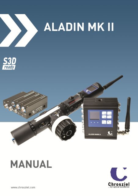
<strong>Ver</strong>sion <strong>1.14</strong>– eng - 2013/11<br />
This document relates to<br />
Receiver Software <strong>Ver</strong>sion 0<strong>1.14</strong>.xx<br />
Transceiver Software <strong>Ver</strong>sion 01.01.xx<br />
<strong>Ver</strong>sion 3
4 Content<br />
Table of Contents<br />
1. Introduction........................................................................................................................7<br />
2. Short Overview ...................................................................................................................8<br />
2.1. Feature List .................................................................................................................8<br />
2.2. Quick Setup Guide........................................................................................................9<br />
2.3. Considerations regarding rf-channel selection with more than one working unit on a<br />
set ....................................................................................................................................10<br />
3. Receiver / Motor Controller..............................................................................................11<br />
3.1. Sockets/ Operation / Optical Signals..........................................................................11<br />
3.2. Receiver Connections ................................................................................................13<br />
3.3. Receiver Menu...........................................................................................................14<br />
4. Extension Interface ..........................................................................................................27<br />
4.1. Extension Base ..........................................................................................................27<br />
4.2. Extension Module “Motor Driver” ..............................................................................28<br />
4.3. Extension Module “Analogue & Digital Demand Units” .............................................28<br />
4.4. Extension Module “Digital Lens Interface” ................................................................29<br />
4.5. Extension Module “Roll & Tilt Sensor” ......................................................................29<br />
5. Transmitter / Hand Control Unit.......................................................................................30<br />
5.1. Transceiver-Module AL-TR-400/800 .........................................................................31<br />
5.2. Transceiver-Module AL-TR-400 MK II .......................................................................32<br />
5.3. FOCUS/ IRIS/ ANGULATION/ BASE – Module (AL-FI).................................................35<br />
5.4. IRIS-Module/ext. Iris (AL-I)........................................................................................36<br />
5.5. ZOOM-Module (AL-Z) .................................................................................................37<br />
5.6. Spreading/reducing the lens travel on <strong>Aladin</strong> Hand Units .........................................38<br />
5.7. Battery & Charger .....................................................................................................40<br />
6. Motor Control with Stereo 3D Applications.......................................................................41<br />
6.1. Preparing the Motor Controller for s3D Operation ....................................................41<br />
6.2. Preparing the Focus/Iris Hand Unit for Inter Axial / Convergence Control ................41<br />
7. Interfacing to external devices .........................................................................................42<br />
7.1. AUX port mode “ALADIN” ..........................................................................................42<br />
7.2. AUX port mode “Dig. Canon”......................................................................................42<br />
7.3. AUX port mode “Fujinon”...........................................................................................43<br />
7.4. AUX port mode “PC-Ctrl”...........................................................................................43<br />
7.5. AUX port mode “MPE 200”.........................................................................................43<br />
8. Connection Examples.......................................................................................................44<br />
8.1. Receiver.....................................................................................................................44<br />
8.2. Remote Control Options.............................................................................................46<br />
9. Trouble Shooting..............................................................................................................47<br />
9.1. HF-error Problems....................................................................................................47<br />
9.2. Motors do not react correctly to Hand Wheel Movement ...........................................47<br />
9.3. Motor does not reach the Lens End Stops..................................................................47<br />
9.4. Receiver does not start up- all three LEDS are on.....................................................47<br />
10. Technical Information.....................................................................................................48<br />
10.1. Pin out of the Connecting Sockets............................................................................48<br />
10.2. Electronic Calibration of the Transmitter’s Hand Wheel / Slider Factory Setup ......50<br />
10.3. Technical Data .........................................................................................................51<br />
10.4. Software updates of the Receiver ............................................................................52<br />
10.5. Declarations of conformity.......................................................................................54
Table of Figures<br />
Content 5<br />
Figure 3 - Motor Controller Top.............................................................................................................11<br />
Figure 4 - Possible Combinations of the Hand Control Unit..................................................................30<br />
Figure 5 - Transceiver Module...............................................................................................................31<br />
Figure 7 - FOCUS/IRIS Module...............................................................................................................35<br />
Figure 8 - External IRIS module.............................................................................................................36<br />
Figure 9 - Zoom Module .........................................................................................................................37<br />
Figure 10 - Set Buttons and Reverse Switch .........................................................................................38<br />
Figure 11 - Diagram Spreading/Reducing .............................................................................................39
6 Introduction
1. Introduction<br />
Introduction 7<br />
The Chrosziel <strong>Aladin</strong> product family is a flexible, reliable and powerful lens and rig control<br />
system operating wireless and wired with several options. It complies with up-scaled<br />
requirements regarding precision and traction even in extreme environmental conditions<br />
like extreme temperatures and associated stiff lenses.<br />
The user can choose between different combinations of the system which can be completed<br />
later. The simple and robust design of the <strong>Aladin</strong> system allows quick-and-easy use and<br />
makes it perfect for the harsh conditions on a film set.<br />
Depending on its stage of extension, <strong>Aladin</strong> controls focus, iris, zoom, base & angulation of<br />
a stereo 3D rig and of course the start/stop functions of your camera. The motor controller<br />
is compatible with the digital encoder motors of the manufacturer BETZ-Tools, Hedén,<br />
Scorpio, „Easylook System“ and Preston. Due to its menu driven operation it is highly<br />
configurable. The user has many options to adapt the behavior of the motor driver to his<br />
needs. New features (requested by customers) can be implemented in future software<br />
releases and easily updated via a standard USB memory stick. The motor controller has<br />
several additional interfaces to the outside, so that it is not just controllable by the<br />
Chrosziel hand unit but also by a standard PC etc. The hand units of the previous model are<br />
compatible and therefore useable with the <strong>Aladin</strong> MARK II motor controller.<br />
The internal power supply for the motor driver allows independence from the input voltage.<br />
An external voltage booster is NOT necessary to get the full power out of your motors.<br />
Additional benefit is granted with the possibility to control lights with the Chrosziel Light<br />
Dimmer. Communication between the hand unit and the motor controller box is bi-<br />
directional. The working frequency is around 434MHz or 869MHz. These ranges where<br />
chosen intentionally because the common band of 2.4GHz is highly frequented by a lot of<br />
other devices like wireless computer networks, video transmission systems or microwave<br />
ovens. Moreover, the propagation of the 434/869 MHz rays is better because it is not<br />
affected by reflections like the 2.4GHz band. Neither a thick stone wall nor a large metal<br />
area (garage door, metal shelf) is a problem. The data packet is CRC-checked which<br />
prevents the data transmission to be received incorrectly. On request, <strong>Aladin</strong> can be<br />
delivered with 869MHz.
8 Introduction<br />
2. Short Overview<br />
2.1. Feature List<br />
Future proof robust hardware design<br />
8 freely assignable on-board motor sockets also useable as spare sockets in case of<br />
a defective channel (number can be increased by the Extension Interface up to 16)<br />
Direct control of up to 2 + 2 digital ENG- lenses (Focus; Iris; Zoom) in conjunction<br />
with the Extension Interface<br />
Menu driven setup with a multi color OLED Display<br />
Modularity of the components meets the needs o f the different users and allows<br />
later upgrades<br />
Radio communication at the 400/800 MHz band allowing safe connection, also over<br />
long distances<br />
Controlled Functions: Focus/Iris/Zoom Base(Inter Axial), Angulation<br />
(Convergence),with highly precise digital encoder motors plus Start & Stop<br />
Smooth zoom movements with precise joystick control<br />
Fluid-like focus hand wheel and iris slider<br />
Control of a local top light through a motor channel and interface possibility to a<br />
DMX-source<br />
Built-In features for S3D- applications (lens & RIG control)<br />
Meta data logging to USB to a *.csv file<br />
Internal time code generator, synchronizeable from external time code<br />
Internal power supply for high torque motor control<br />
Automatic maximum power level adjustment during end-stop calibration to handle<br />
stiff or easy-going lenses, additional 3 level motor torque pre selection for every<br />
single motor channel<br />
Adjustable backlash compensation for each single motor<br />
USB & 2x RS232/RS422 Interface<br />
Easy Software update via USB- Stick<br />
… and more<br />
Chrosziel extends your ALADIN with new software features on request.
2.2. Quick Setup Guide<br />
1. Rotate lens ring away from the end stops<br />
Introduction 9<br />
2. Mount receiver to the rods either with the RMB or with articulating arm 550-MA<br />
through the 1/4" thread in the receiver housing<br />
3. Power receiver before before connecting the Motors, because this clears previous lens<br />
limit calibrations!<br />
4. Mount required motors on the rods of the lens support and engage motors onto lens<br />
gear. Please note: The repeatability of the positioning is directly dependent to how<br />
tight you fit the motors to the lens and how close the gears are fit together!<br />
5. Check radio channel on appropriate menu entry<br />
6. Connect antenna to hand unit and receiver<br />
7. Connect power supply cord (i.e. with XLR4-AL2). LED for each motor channel lights<br />
briefly, and then goes off again. The green LED at the membrane keypad lights up,<br />
as well as the red LED for rf- reception error if hand unit is not switched on.<br />
8. Load default values, if you’d like to start with a known standard configuration<br />
9. If required, configure the camera record start/stop mode in menu entry “CAM-<br />
Control” and connect special cable for the camera start/stop function<br />
10. Connect motors to the desired motor sockets with the cable AMOTD60/100. LEDs<br />
for each motor channel should flash slowly now. The configuration screen shows<br />
which motor channels (M1 – M8) are attached to which function<br />
(Focus/Iris/Zoom/Base/Angulation)<br />
11. Perform motor calibration for each function (Focus/Iris …) by pressing the desired<br />
button on the membrane keypad (the main screen must be visible). The motor(s)<br />
connected to this function will start the lens calibration process immediately and<br />
simultaneously. The motor status LEDs for those motors will flash quickly in<br />
addition. The lens-scale limits will be checked and stored automatically. Values<br />
remain stored during power off!<br />
12. If procedure for a motor channel passed successfully, its LED will go off, if not it<br />
stays flashing (short on longer off), indicating the failure status<br />
13. Install required modules of the hand unit together (i.e. antenna, transceiver module,<br />
focus/iris, battery).<br />
14. Check if rf-channel is the same as on the receiver box<br />
15. Switch on the hand unit. The “rf-error”-LEDs on hand unit and receiver should now<br />
turn off.<br />
16. Check motor end stops by turning the hand wheel/slider from one side to the other.<br />
The end stops of the hand wheel/slider must correspond to the end stop of the lens.<br />
If not try to reset the spreading on the hand unit (see Chapter 5.6 “travel “ on page<br />
38.)<br />
17. Select “reverse” switch on the hand unit to the desired direction<br />
18. On the zoom channel, choose the displaying direction of the LED-band (see topic<br />
5.5.4 on Page 37).
10 Introduction<br />
2.3. Considerations regarding rf-channel selection with more than<br />
one working unit on a set<br />
If there are more then one ALADIN operated on set, care has to be taken regarding the<br />
selection of the rf-channel of each single receiver/ hand controller combination. It is not<br />
just important to select different channels but also to select channels which have enough<br />
space from each other in the channel raster. This avoids the physical effect of inter-<br />
modulation in the receivers and therefore prevents interference with each other.<br />
The table below is a suggestion which channels to select for up to 5 ALADINs operated<br />
simultaneously:<br />
Alternatively:<br />
Alternatively:<br />
Alternatively:<br />
Alternatively:<br />
ALADIN 1 Rf-Channel 0 ALADIN 1 Rf-Channel 0<br />
ALADIN 2 Rf-Channel 8 ALADIN 2 Rf-Channel 1<br />
ALADIN 3 Rf-Channel C/12 ALADIN 3 Rf-Channel 3<br />
ALADIN 4 Rf-Channel E/14 ALADIN 4 Rf-Channel 7<br />
ALADIN 5 Rf-Channel F/15 ALADIN 5 Rf-Channel D/13
3. Receiver / Motor Controller<br />
3.1. Sockets/ Operation / Optical Signals<br />
Figure 1 - Motor Controller Front Panel<br />
Figure 2 - Motor Controller Rear Panel<br />
Full Color OLED Graphic<br />
Display<br />
Status LEDs<br />
RF-Error, Power,<br />
CAM-Relay<br />
Figure Figure 3 - Motor Motor Controller Controller Top<br />
Top<br />
3.1.1. Sockets „MOTORS 1 – 8” (Lemo 7 Pin)<br />
Details 11<br />
Connect external digital servo motors with incremental encoder, such as motors from the<br />
manufacturers BETZ-Tools, Hedén (M26VE), Scorpio, „Easylook System“ and Preston.<br />
3.1.2. Socket „POWER/CAMERA“ (Lemo 2 and 5 pin)<br />
These sockets are used for the connection of the external power supply (voltage 10-30V).<br />
The Lemo 5pin also controls the start/stop-function of film and video cameras and accepts<br />
LTC time code signal for synchronizing the internal time code.<br />
3.1.3. Sockets „AUX1 - 2“<br />
Motor Status LEDs<br />
These sockets interface to the digital ENG-Lenses and other additional accessories like a<br />
controlling PC. Functions can be assigned within the setup menu.<br />
Membrane Keypad
12 Details<br />
3.1.4. Socket „ANTENNA“<br />
This BNC socket connects the 400/800 MHz band antenna to the receiver. In case of<br />
extremely bad reception due to i.e. broadband interferences or very long distance with<br />
more than 100 m, the connection between the transmitter and the receiver can be made by<br />
a standard BNC cable.<br />
3.1.5. USB port<br />
You may either connect the unit to a PC via the smaller mini AB USB port or attach an USB<br />
stick to the large USB A type port. Both connections MUST NOT are made simultaneously! In<br />
the current software version, the larger USB port can be used for software updates via USB<br />
memory stick and data logging. A PC connection is currently NOT supported.<br />
3.1.6. Membrane Keypad<br />
The keypad consists of 6 multifunctional buttons.<br />
If the menu main page “Motor Limits” is active they can be used to directly initiate<br />
the motor calibration without going into the setup menu.<br />
Holding down the ESC and the OK button simultaneously will lock/unlock the<br />
keypad.<br />
Pressing OK will always enter the next level on the menu while ESC will go back.<br />
When pressing the ESC button for more than 2 seconds, the unit will switch to<br />
standby mode.<br />
3.1.7. LEDs integrated on membrane keypad<br />
There are 3 LEDs below the OLED display. These LEDs indicate several important status<br />
information, even if the display turns off after a while (screen saver function).<br />
The LEDs are placed as follows:<br />
Red LED: Indicates RF reception error when it is on meaning that there is no proper<br />
connection to the hand unit via antenna. It is also on in stand by mode.<br />
Green LED: Indicates operational mode. In stand by mode it is switched off.<br />
Blue LED: Turns on, when relay contacts for camera record start/stop control are<br />
3.1.8. FUSE<br />
operated.<br />
The ALADIN <strong>MKII</strong> motor controller is equipped with an electronic over-current protection. If<br />
the unit exceeds 10A, this fuse will switch it off. To reset this condition you will have to<br />
disconnect the unit from the main power. The unit also has a reverse protection on the<br />
power input line. Improperly made power cables with wrong polarity connection will not<br />
damage the unit or the power source (i.e. camera power outlet). The unit’s main power<br />
entry also provides a soft-start circuitry making a main power switch obsolete.
3.2. Receiver Connections<br />
3.2.1. External digital Motors und Power Supply<br />
Details 13<br />
External motors (Hedén M26VE, BTM7, Scorpio SB92, „Easylook System“ or Preston DM2)<br />
are connected through the „AMOTDxx“-cable to the sockets labeled with “MOTOR 1 - 8”.<br />
Power (10-34V) is applied either through the 2-Pin Lemo connector for high power<br />
requirements or through the 5-pin Lemo connector for standard power requirements<br />
and/or “Camera Record Start/Stop” control.<br />
3.2.2. Chrosziel Light Dimmer for Standard Camera Lights<br />
The Chrosziel Light Dimmer for camera lights is connected through one of the MOTOR<br />
sockets. This motor channel (1..8) needs to be configured for light dimming in the setup<br />
menu. Power supply of the light dimmer has to be fed through its own „POWER IN „socket.<br />
Operate the Light Dimmer at 10 – 14.5V only! The light output can be controlled by an<br />
<strong>Aladin</strong> Hand controller with slider or hand wheel as well as with the Colibri transmitter unit<br />
via DMX- Interface.<br />
Go to through Set up Menu and configure one of the motor channels as described in topic<br />
3.3.4.1 “M2 Setup” on page 15.<br />
3.2.3. Digital ENG Lenses<br />
If the control of one or two digital ENG Lenses is required, these lenses will be connected to<br />
the sockets AUX 1-2 by a special control cable. The AUX sockets need to be configured for<br />
digital lens control in the setup menu.<br />
3.2.4. Extension Interface<br />
The Extension Interface (AL2-EXT-BASE) can be connected to socket AUX1 with cable AL2-<br />
INTF. Because the Extension Interface features a Loop-Trough connector, the serial port<br />
AUX1 is still available.
14 Details<br />
3.3. Receiver Menu<br />
Please note: Menu content may change with further software versions.<br />
Pressing the OK-button will enter next menu level or confirm a modification. Vise versa the<br />
ESC button moves control one level back or cancels a modification. Arrow buttons select an<br />
item and -/+ buttons modify the value of an item. Holding down + or - button for more than<br />
one second will start a loop repeating the last button event quickly. Please refer to topic<br />
3.1.6 Membrane Keypad on page 12 above.<br />
3.3.1. Start up Screen<br />
<strong>Ver</strong>sion:<br />
01.11.xx<br />
3.3.2. Info Screen<br />
Cal. Motors (F/I/Z/3D)<br />
T<br />
F m<br />
I T<br />
SETUP(OK)<br />
AUX: <strong>Aladin</strong> /Off<br />
TC 25 – 00:43:57:24<br />
Chan. 15/434.100<br />
USB OK<br />
Z mm<br />
C. Dist m<br />
R H<br />
Recording<br />
USB OK/ Recording<br />
8.00<br />
5.6<br />
50<br />
14.00<br />
50.0<br />
This screen comes up when starting the unit. The current software<br />
version is displayed.<br />
This is the first screen after start up with direct access access access to the<br />
motor calibration of each control function (Calibration starts<br />
directly after pressing buttons (F), (I), (Z) or (3D = Convergence & IA<br />
motor)). Additional virtual LEDs inform about the state of the<br />
connection to the desired hand controller function. They light up<br />
green, if a hand control unit is active for the control function in the<br />
corresponding line.<br />
For 3D there are 2 + 3 LEDs for Convergence and Inter Axial as well as for the Tilt, Roll &<br />
Height function. The functions Focus and Zoom feature two LEDs each. The left of these<br />
LEDs indicates the connection state of the standard ALADIN hand units where as the right<br />
ones light up if behind camera demand units for Focus and /or Zoom are connected through<br />
the Extension Interface.<br />
Additionally the current Lens and Rig data are displayed. Meta Meta values values are are are assumed assumed to to to be be<br />
be<br />
right right right only only if if a a setup setup of of these these data data has has been been been done done in in the the meta meta da data da ta menu entries.<br />
The info area on the bottom of this screen consists of 3 lines. First line indicates the<br />
selected mode of the two on-board serial AUX-sockets. In this example AUX1 (12Pin Lemo)<br />
is assigned for ALADIN Hardwire Control while AUX2 (7Pin Lemo) has no function assigned.<br />
The second line displays the current time code and its format. The third line informs about<br />
currently selected radio channel & center frequency as well as the RF signal strength from<br />
hand unit on current frequency. This line will change its content when the receiver changes<br />
the record mode of the camera to ON (“Recording”) or if an USB memory stick is connected<br />
(“USB OK”). - Press (OK) for further set-up steps. -
3.3.3. Set Up Screen<br />
Set Up<br />
Int. Encoder Mot.<br />
Ext. Encoder Mot.<br />
ENG- Lenses<br />
Power<br />
Radio Channel<br />
CAM-Control<br />
Backup/Restore<br />
Advanced Setup<br />
This is the main entry for several setup topics of the receiver.<br />
3.3.4. Internal/ External Encoder Motor Config.<br />
Motor- Config.<br />
M1: F(Cal. Motor)<br />
M2: F(norm,…)<br />
M3: I(No Motor!)<br />
M4: I(No Motor!)<br />
M5: Z(norm,…)<br />
M6: Z(norm,…)<br />
M7: C(norm,…)<br />
M8: IA(extend,…)<br />
[OK]->Test Limits<br />
3.3.4.1. M2 Setup-Examples<br />
M2 Setup<br />
Link To: F<br />
Mode : motor<br />
Range : norm<br />
Direction : norm<br />
Backlash : 1<br />
Torque: Full<br />
[OK]->Test Limits<br />
[OK]-> Clear Fault<br />
Details 15<br />
Configuration entry screen for every single on-board or external<br />
motor channel. Motor M1 is connected but motor limits are not<br />
calibrated. M8 is operating in extended mode which means 4 times<br />
more calibration range and an enlarged safety distance to the end<br />
stops. The The range range for for External External Encoder Encoder Motors Motors is is M9 M9-M16. M9 M16.<br />
Example 1:<br />
A motor can be linked to one out of following functions:<br />
(F)ocus, (I)ris, (Z)oom,(C)onvergency, (IA)-Interaxial, (T)ilt, (R)oll &<br />
(H)eight.<br />
In this example motor channel 2 is assigned to the focus signal in<br />
motor mode, with normal distance range and is turning in standard<br />
direction.<br />
Backlash compensation is set to level 1 out of 50. The torque of motor 2 is at maximum<br />
level. Other torque levels are Mid = 50% and Low = 25%.<br />
Each motor channel can be tested against the mechanical end stops separately from this<br />
menu entry. You may clear a motor fault condition if motor was stalled by highlighting<br />
“Clear Fault” and pressing OK. So you do not need to recalibrate this motor, but make sure<br />
that the motor still operates within the mechanical limits of the attached axis!<br />
M2 Setup<br />
Link To: I<br />
Mode : dimmer<br />
Range :<br />
Direction : norm<br />
Example 2:<br />
Configuration for Motor 2 as a dimmer output. A camera 12V head<br />
light can be controlled through the Chrosziel <strong>Aladin</strong> Light Dimmer.<br />
Motor channel 2 is assigned to the iris signal (slider), Dimming<br />
direction is normal: 100% level in is 100% level out.<br />
Adjust values with -/+ buttons.
16 Details<br />
M2 Setup<br />
Link To: *<br />
Mode : motor<br />
Range : norm<br />
Direction : norm<br />
Backlash : 0<br />
Torque: Low<br />
[OK]->Test Limits<br />
[OK]-> Clear Fault<br />
Example 3:<br />
3.3.5. ENG Lenses - Setup Screen<br />
ENG-Lenses<br />
Lens A: on on on<br />
Lens B: on on on<br />
Lens C: off off off<br />
Lens D: off off off<br />
Save & Exit Cancel<br />
Lens Setup<br />
F: on I: off Z: on<br />
Motor 2 is not assigned (*) to any of the hand controller channels<br />
(F/I/Z/C/IA/T/R/H). It only can be controlled in PC-Control- Mode by<br />
a special control protocol! The maximum torque is only 25%.<br />
This Setup Screen allows for configuring the access to the<br />
functions F/I/Z by the ALADIN Main Unit and Extension Interface.<br />
The entry list informs about the activation status of these functions<br />
for the 4 supported lenses (A-D). Select a lens from the list and<br />
press the OK button. In the sub screen select the function to be<br />
changed and press the -/+ buttons on the keypad for modification.<br />
Press OK to go back to the list of lenses.<br />
Finally select the “Save&Exit” entry and hit the OK button.<br />
Following table references the lens indices (A-D) to there location.<br />
Lens Lens Index Index Location Location<br />
Location<br />
A Main Unit AUX1(*) or<br />
front socket on second lens control module on<br />
Extension Interface (i.E. Channel 11)<br />
B Main Unit AUX2(*) or<br />
rear socket on second lens control module on<br />
Extension Interface (i.E. Channel 12)<br />
C Front socket on first lens control module on<br />
Extension Interface (i.E. Channel 9)<br />
D Rear socket on first lens control module on<br />
Extension Interface (i.E. Channel 10)<br />
(*) If Canon/Fujinon lens control mode is activated in the AUX-Port Setup menu.<br />
If If one one of the AUX sockets sockets is is in in lens lens control mode the the lenses A&B A&B are NOT available on<br />
extension extension Interface!<br />
Interface!
3.3.6. Power Set up Screen<br />
Power<br />
Motor Torque (1-5) 3<br />
Max. Input Current 4<br />
Amps<br />
3.3.7. RF Channel Selection Screen<br />
Set RF-Channel<br />
Chan.: 2<br />
Freq. : 434.1000<br />
Radio: on<br />
Spectrum<br />
Details 17<br />
Adjustment of over all motor torque for all motors in 5 steps and<br />
adjustment of maximum input current. If input current reaches<br />
selected level, the max. motor torque is reduced in order to reduce<br />
the total power consumption to allowed level. The power<br />
consumption depends on number of motors connected, selected<br />
motor torque and stiffness of attached Lens / Rig gears.<br />
Adjust values with -/+ buttons.<br />
RF Channel selection and information about occupied or interfered<br />
frequencies/ channels. Currently selected channel is 2. Adjust<br />
channel with -/+ buttons. The green pointer indicates placement<br />
within the channel steps. Interference is visible on channel 9. The<br />
wireless module can be switched On & Off as well from this menu.<br />
If switched Off there will be no wireless connection available from<br />
the hand controller.<br />
Please Please note: note: If If this this screen screen is is is visible visible the the wireless wireless connection connection is is disconnected disconnected to to all<br />
all<br />
hand hand controllers controllers because because the the receiver receiver scans scans through through all all available available available rf rf rf channels channels at at this this<br />
this<br />
time time searching searching for for for possible possible possible interferences.<br />
interferences.<br />
3.3.8. CAM-Control Set up Screen<br />
CAM Control<br />
Record Mode:<br />
Pulse<br />
Start Stop<br />
3.3.9. Back Up/ Restore Screen<br />
Backup/Rest. USB<br />
File Index 3<br />
(S)tore<br />
Lens Match.<br />
Rig. Data<br />
Lens Meta<br />
Config<br />
(L)oad<br />
S L<br />
S L<br />
S L<br />
S L<br />
Load Factory Def.<br />
Select the mode of the control signal the camera needs to<br />
enter/exit recording mode.<br />
There are two modes:<br />
Pulse: Record starts & stops with a closure/open cycle of the relay<br />
contacts (toggle mode)<br />
Static: As long as the relay contacts are closed, the camera is<br />
recording, otherwise the camera stops recording<br />
This screen allows the user to save/ restore several settings of the<br />
unit to/from an external USB memory stick. All file operations are<br />
addressed by a preselected index index, index which ranges between 0 – 255.<br />
The files stored by the ALADIN can be copied to other locations for<br />
backup reasons or can be copied to another memory stick.<br />
Please Note: All files need to be placed in the root directory of the<br />
storage device so that the ALADIN can load these files.
18 Details<br />
… … Config: Config: This “clones” a unit setup including lens, motor, power and auxiliary ports<br />
assignments. The physical file names on the storage device range from “<strong>Aladin</strong>CFG_0”...<br />
“<strong>Aladin</strong>CFG_255” .<br />
… … Lens Lens MMatch.<br />
M<br />
atch. atch.: atch. The lens matching data (S3D tweaking) regarding Focus, Iris and Zoom of<br />
the current lens set are stored/ loaded. The physical file names on the storage device range<br />
from “<strong>Aladin</strong>LENSMATCH_0”... “<strong>Aladin</strong>LENSMATCH_255”.<br />
… … Lens Lens Meta. Meta.: Meta.<br />
The lens data (lens tables) regarding Focus, Iris and Zoom scale of the<br />
current lens set are stored/ loaded. The physical file names on the storage device range<br />
from “<strong>Aladin</strong>LENSMETA_0”... “<strong>Aladin</strong>LENSMETA_255” .<br />
… … Rig Rig Data Data: Data<br />
The rig data regarding type of rig, IA and Convergence values and zero offsets<br />
are stored/ loaded. . The physical file names on the storage device range from<br />
“<strong>Aladin</strong>RIG_0”... “<strong>Aladin</strong>RIG_255” .<br />
… Factory Factory Factory Def.: Def.: Def.: This loads the complete default configuration. Lens/rig matching & meta<br />
data will be reset as well.<br />
3.3.10. Set up Screen “Advanced”<br />
Advanced Setup<br />
Handcontroller<br />
AUX-Ports<br />
Lens Data<br />
Rig Data<br />
Matching<br />
Roll & Tilt Sensor<br />
Entry screen for several advanced set up topics like routing of the<br />
hand controller channels to desired functions, assigning the<br />
operation mode of the two on-board serial AUX ports as well as<br />
setting up real world meta data (lens tables) or s3D rig<br />
configurations.<br />
There are 2 on-board rig&lens matching/meta data presets which<br />
are selected directly by pressing the -/+ -buttons.<br />
The presets can be modified within the matching setup screen and/or in the Meta-Data<br />
menu. The presets hold the data for an s3D rig in the same manner. Motor assignments like<br />
function and direction will not change. If more than the available on-board setups need to<br />
be stored and recalled, an USB memory stick can be used for storing.<br />
Select the current lens matching preset with -/+.<br />
3.3.11. Hand Controller Set Up<br />
Handcontroller<br />
First Hand Wheel<br />
First Slider<br />
Zoom Module<br />
Second Hand Wheel<br />
Second Slider<br />
Save&Exit<br />
This menu allows to reassign the 5 available hand controller<br />
channels (F,I,Z,C&IA) to different functions (F,I,Z;C,IA,T,R,H) in the<br />
receiver or disable the channel (assign an * to it) .<br />
The assignment is mutually exclusive meaning that two different<br />
hand controller channels can not be assigned to the same function<br />
in the receiver. In order to change a hand controller channel<br />
highlight the desired controller function, press OK and assign the new controlled function to<br />
this hand controller channel. As long as “Save&Exit” is not executed, the assignment is<br />
temporarily only. If the menu is exit without saving the prior hand controller setup is<br />
restored.<br />
F<br />
I<br />
Z<br />
C<br />
IA
3.3.12. Serial Port (AUX) Setup-Screen<br />
Serial Port Setup<br />
AUX1: Canon Dig<br />
F: on I: off Z: on<br />
RS422/76800/8/E/1<br />
AUX2: PC-Ctrl.<br />
RS232/57600/8/N/1<br />
Configuration of the two on-board serial ports AUX1 & AUX2.<br />
Details 19<br />
AUX1 is configured for direct Focus/Zoom-control of the Canon<br />
Digital lens servo. COM2 is configured to accept control data from a<br />
PC. Please feel free to ask Chrosziel for technical details about the<br />
PC- control protocol. Buttons -/+ select the operational mode.<br />
Up/down- buttons set focus to desired switchable options. For<br />
currently available control modes refer to topic 7 “Interfacing to<br />
external devices” on page 42 below.<br />
For every serial device the hardware layer can be switched between RS232 or RS422 mode<br />
with buttons -/+.<br />
3.3.13. Meta Data Screen<br />
Lens&Rig Data<br />
F m<br />
I T<br />
Z mm<br />
Conv. m<br />
IA mm<br />
Record to<br />
Measure<br />
5.5<br />
2.3<br />
75<br />
3.50<br />
150<br />
USB<br />
meter<br />
F ft<br />
F ft<br />
IA inch<br />
imperial<br />
This screen serves as an overall display of current meta<br />
data as well as the starting point to enter this data. The<br />
displayed data are to be assumed correct only if they are<br />
assigned properly in the subsequent calibration menus.<br />
The display may toggle between imperial and metric<br />
measurement. To change the scale of measure highlight<br />
entry “Measure” and adjust the scale by pressing the -/+ -<br />
button on the key pad.<br />
Meta data will change by selecting a different lens set. All changes made in the meta data<br />
setup menus correspond to the currently selected lens set. Meta data displayed here will be<br />
stored in a *.csv file to an USB-memory stick if the unit is in recording state and the stick is<br />
plugged in. The way of applying the meta data of any lens manually makes the user<br />
independent from big data bases on a “What You See Is What You Get” - basis. Not having<br />
the lens file already prepared for a desired lens will NOT stop the operator any more from<br />
using it on set because the data can be entered manually - if needed.<br />
Important: Important: before before calibrating calibrating the the meta meta data data make make sure, sure, that that the the matching matching of of every every lens<br />
lens<br />
motor motor has has been completed (on s3D applications) or is switched of off of and and backlash<br />
backlash<br />
compensation compensation is is applied applied applied if if necessary.<br />
necessary.<br />
Always Always Always press press OK OK button button when when finished finished in in order order to to store store your your changes!<br />
changes!<br />
3.3.13.1. Considerations regarding capturing of lens Meta data<br />
The Meta data are input to the unit manually by the user but can be restored later on by just<br />
loading it from an USB memory stick. The data calculation is based on a look-up table with<br />
16 sample points. Each sample point contains a pair of motor position and a corresponding<br />
Meta value like 5ft, T5.6 or 80 mm. Depending on the type of Meta data (focus, iris (T), zoom)<br />
all points can be moved freely regarding motor position. So the sample points can be<br />
assigned very flexible. In the Meta data set up menu these points are called “Travel” and
20 Details<br />
are addressed by an index ranging from 2 – 15. Both mechanical end stops of the lens (point<br />
1 & 16) have special meaning as follows:<br />
Focus: Focus: Lower end stop = nearest focus distance i.E. 0.45 m; Upper end stop = infinity focus<br />
distance or above<br />
Remarks: because the value for infinity might lie before the upper mechanical end stop of<br />
the lens, the exact motor position for this point needs to be assigned.<br />
Focal Focal distance distance in in meter<br />
meter<br />
1000<br />
100<br />
10<br />
1<br />
0,1<br />
Sample Sample points points for for Focus Focus meta<br />
meta<br />
Motor Motor travel<br />
travel<br />
IRIS: IRIS: IRIS: Lower end stop = open T value; Higher end stop = Iris Close position<br />
Remarks: the Close position can be also before the upper mechanical end stop of the lens<br />
or on the other hand the lens does not feature a closed iris, but just iris values up to T16<br />
T T values<br />
values<br />
25<br />
20<br />
15<br />
10<br />
5<br />
0<br />
Lower<br />
end stop<br />
Lower<br />
end stop<br />
Near<br />
MeOpen<br />
Open Meta<br />
Sample Sample points points for for Iris Iris meta<br />
meta<br />
Motor Motor Motor travel<br />
travel<br />
Zoom: Zoom: Lower end stop = Widest focal length i.e. 8 mm; upper end stop = far focal length<br />
(tele) i.E. 75 mm<br />
Travel Points 2 - 15<br />
Travel Points 2 - 15<br />
Infinty motor position<br />
Close Iris motor position<br />
Upper<br />
end stop<br />
Upper<br />
end stop
Focal Focal length length mm<br />
mm<br />
80<br />
70<br />
60<br />
50<br />
40<br />
30<br />
20<br />
10<br />
0<br />
Lower<br />
end stop<br />
Wide Meta<br />
Sample Sample Sample points points for for Zoom Zoom meta<br />
meta<br />
Travel Points 2 - 15<br />
Motor Motor travel<br />
travel<br />
Tele Meta<br />
Upper<br />
end stop<br />
Details 21
22 Details<br />
3.3.13.2. Lens Data Focus<br />
Lens Data Focus<br />
Near Meta<br />
Infinite Pos.<br />
Ref. Point 2<br />
Meta Val.<br />
Lens Pos.<br />
Def. Scale<br />
0.30<br />
+/-<br />
0.60<br />
+/-<br />
Rev. Motor<br />
Select with<br />
Move/Adjust with +/-<br />
Cal. Entry Meaning<br />
This screen allows calibrating the Focus meta data in the currently<br />
selected lens set/file on the fly and in the field.<br />
Arrow buttons of the key pad step through the several adjustment<br />
topics while the -/+ -buttons will modify the selected item.<br />
“Near Meta” : Focus motor(s) are driven to the lower mechanical end stop, lens ring should show<br />
the lowest focus distance. Modify meta data value corresponding to that point by<br />
pressing the -/+ -button on key pad. If motor turns in the wrong direction, highlight<br />
the “Rev. Motor” entry and press the OK button on the key pad. All motors linked to<br />
the focus function will change their direction of rotation.<br />
“Infinite Pos.” : Focus motor(s) are driven to the higher mechanical end stop; lens ring should<br />
point close to the infinite focal distance. Adjust the exact position of the infinite<br />
mark with -/+ -buttons.<br />
“Ref. Point” : This selects the intermediate calibration positions 2 – 15 out of 16 (Positions 1 & 16<br />
are reserved for the mechanical end stops).<br />
“Meta Val." : Observe the current motor position on the lens and match the current displayed<br />
meta data value with the one from the lens. If lens ring is not exactly positioned on a<br />
straight meta data value (which will be the case in most situations) adjust the<br />
displayed meta data value to a close point displayed on the lens ring and match the<br />
motor position (“Lens Pos.”) so that the lens ring will point to the displayed meta<br />
data value which was adjusted at that point. So in fact two parameters can/have to<br />
be modified on each calibration positions. When finished repeat procedure up to<br />
travel point 15. When adjusting the SAME lens position and meta data value to more<br />
than one calibration point those points will be blank off as if they did not exist. This<br />
can speed up the alignment procedure if not all 16 points are needed.<br />
“Lens Pos.” : Moves lens motor to achieve a precise matching of lens ring position against<br />
displayed meta data value.<br />
“Def. Travel” : Loads default values which provide a point to start with a new adjustment.<br />
“Rev. Motor” : Reverses the direction of rotation of all motors linked to the current function.<br />
Press OK button on key pad to reverse the motors. After pressing OK button the first<br />
calibration entry will be highlighted.
3.3.13.3. Lens Data Iris<br />
Lens Data Iris<br />
Open Meta<br />
Close Pos.<br />
Ref. Point 2<br />
Meta Val.<br />
Lens Pos.<br />
Def. Scale<br />
1.0<br />
+/-<br />
1.6<br />
+/-<br />
Rev. Motor<br />
Select with<br />
Move/Adjust with +/-<br />
Cal. Entry Meaning<br />
Details 23<br />
This screen allows calibrating the Iris meta data in the currently<br />
selected lens set/file on the fly and in the field.<br />
Arrow buttons of the key pad step through the several adjustment<br />
topics while the -/+ -buttons will modify the selected item.<br />
“Open Meta” : Iris motor(s) are driven to the lower mechanical end stop; lens ring should show<br />
the Open Iris T stop. Modify meta data value corresponding to that point by pressing<br />
the -/+ -button on key pad. If motor turns in the wrong direction, highlight the “Rev.<br />
Motor” entry and press the OK button of the key pad. All motors linked to the Iris<br />
function will change their direction of rotation.<br />
“Close Pos.” : Iris motor(s) are driven to the higher mechanical end stop; lens ring should point<br />
around T16/Close stop. Adjust the exact position of the Close mark with -/+ -<br />
buttons. If If lens lens does does not not feature feature a a Close Close Value Value but but just just T16 T16 adjust adjust this this point point to<br />
to<br />
the the mechanical mechanical end end stop stop and and do do the the same same with with travel travel point point 15 15 (see (see below).<br />
below).<br />
“Ref. Point” : This selects the intermediate calibration positions 2 – 15 out of 16 (Positions 1 & 16<br />
are reserved for the mechanical end stops).<br />
“Meta Val." : Observe the current motor position on the lens and match the current displayed<br />
Iris meta data value with the one from the lens. If lens ring is not exactly positioned<br />
on a straight meta data value (which will be the case in most situations) adjust the<br />
displayed meta data value to a close point displayed on the lens ring and match the<br />
motor position (“Lens Pos.”) so that the lens ring will point to the displayed meta<br />
data value which was adjusted at that point. So in fact two parameters can/have to<br />
be modified on each calibration positions. When finished repeat procedure up to<br />
travel point 15. When adjusting the SAME lens position and meta data value to more<br />
than one calibration point those points will be blank off as if they did not exist. This<br />
can speed up the alignment procedure if not all 16 points are needed. If lens does<br />
not feature a T Close but just T16 move lens in position 15 to the end stop and adjust<br />
the corresponding meta data value to 16 or 22- whatever T Val the lens got on the<br />
upper end.<br />
“Lens Pos.” : moves lens motor to achieve a precise matching of lens ring position against<br />
displayed meta data value.<br />
“Def. Travel” : Loads default values which provide a point to start with a new adjustment.<br />
“Rev. Motor” : Reverses the direction of rotation of all motors linked to the current function.<br />
Press OK button on key pad to reverse the motors. After pressing OK button the first<br />
calibration entry will be highlighted.
24 Details<br />
3.3.13.4. Lens Data Zoom<br />
Lens Data Zoom<br />
Wide Meta<br />
Tele Meta<br />
Ref. Point 2<br />
Meta Val.<br />
Lens Pos.<br />
Def. Scale<br />
8.0<br />
75.0<br />
12.0<br />
+/-<br />
Rev. Motor<br />
Select with<br />
Move/Adjust with +/-<br />
Cal. Entry Meaning<br />
This screen allows calibrating the Zoom (focal length) meta data in<br />
the currently selected lens set/file on the fly and in the field.<br />
Arrow buttons of the key pad step through the several adjustment<br />
topics while the -/+ -buttons will modify the selected item.<br />
If the lens is a fixed type adjust the wide and the tele meta data value<br />
to the same number i.e. to 75. Adjustment of the intermediate<br />
calibration positions 2 – 15 is not done in this case!<br />
“Wide Meta” : Zoom motor(s) are driven to the lower mechanical end stop; lens ring should show<br />
the shortest focal length (in this example 8). Modify meta data value corresponding<br />
to that point by pressing the -/+ -button on key pad. If motor turns in the wrong<br />
direction, highlight the “Rev. Motor” entry and press the OK button of the key pad.<br />
All motors linked to the Zoom function will change their direction of rotation.<br />
“Tele Meta” : Zoom motor(s) are driven to the higher mechanical end stop. Lens ring should<br />
point on the maximum focal length. Modify meta data value corresponding to that<br />
point by pressing the -/+ -button on key pad (in this example 75).<br />
“Ref. Point” : This selects the intermediate calibration positions 2 – 15 out of 16 (Positions 1 & 16<br />
are reserved for the mechanical end stops).<br />
“Meta Val." : Observe the current motor position on the lens and match the current displayed<br />
meta data value with the one from the lens. If lens ring is not exactly positioned on a<br />
straight meta data value (which will be the case in most situations) adjust the<br />
displayed meta data value to a close point displayed on the lens ring and match the<br />
motor position (“Lens Pos.”) so that the lens ring will point to the displayed meta<br />
data value which was adjusted at that point. So in fact two parameters can/have to<br />
be modified on each calibration positions. When finished repeat procedure up to<br />
travel point 15. When adjusting the SAME lens position and meta data value to more<br />
than one calibration point those points will be blank off as if they did not exist. This<br />
can speed up the alignment procedure if not all 16 points are needed.<br />
“Lens Pos.” : moves lens motor to achieve a precise matching of lens ring position against<br />
displayed meta data value.<br />
“Def. Travel” : Loads default values which provide a point to start with a new adjustment.<br />
“Rev. Motor” : Reverses the direction of rotation of all motors linked to the current function.<br />
Press OK button on key pad to reverse the motors. After pressing OK button the first<br />
calibration entry will be highlighted.
3.3.13.5. RIG Meta Data<br />
Rig SetUp<br />
Cal. Entry Meaning<br />
Details 25<br />
This screen allows calibrating and assigning all necessary data to<br />
enable the use of convergence tracking and /or retrieving the meta<br />
data of the used s3D rig.<br />
“Basic Rig Data” : This opens a sub menu entry for the input of raw IA and convergence read outs<br />
“Adj. IA zero” & “Adj. C<br />
Inf.”<br />
+/-<br />
Basic Rig SetUp ><br />
Adj. IA zero +/-[OK]<br />
Adj. C Inf. +/-[OK]<br />
Adj. Real C Dist ><br />
Limit IA to: 50.00<br />
Min. C.Dist: 2.33<br />
Lck. C to IA: on<br />
Save&Exit Cancel<br />
of the rig as well as the type of rig.<br />
: Highlight one of the topics.<br />
In case hand controller is switched off: the rig is driven to the currently stored<br />
zero/infinity positions of IA* (on mirror rig) and convergence. Drive both axis with<br />
-/+ buttons to meet requirements for a proper aligned rig (converge IA* with a<br />
close object and C with a far object on screen).<br />
In case hand controller is switched on: on: the rig is driven on demand of the hand<br />
units slider and wheel instead of the -/+ buttons. If rig is aligned, press OK button<br />
to apply current hand unit positions as zero*/infinity positions.<br />
“Min. C. Dist.:” This is a read-only entry. It shows the calculated minimum convergence distance<br />
if the unit runs in “convergence tracking” mode, which means the minimum<br />
distance the rig could converge with the maximum IA distance in order to<br />
guaranty the tracking function over the full range of the IA.<br />
“Lck. C to IA:” This switches the convergence tracking mode on or off.<br />
Rig Basic Settings<br />
RIG-Type<br />
Mirror<br />
Counter/Scale Readings<br />
IA min.<br />
IA max.<br />
Rev. IA Motor<br />
-20.5<br />
84.00<br />
C Ang. min<br />
C Ang. max 2.43<br />
Rev. C Motor<br />
-2.35<br />
Current Conv. Dist.<br />
Drive Conv. +/-<br />
Currt. C Dist. 14.10<br />
* On Mirror Rig only<br />
This screen allows assigning the type of rig which can be “Mirror” or “SBS” (Side by<br />
Side) as well as the basic measures for IA and Angulation with the -/+ buttons on the<br />
key pad. When high lighting one of the min. /max. values the rig is driven to the<br />
desired mechanical end stop in order to make the true readout visible on the rig as<br />
it is entered at the same time. The hand controller is disabled and has no influence<br />
when doing these adjustments.<br />
Once entered all values press OK to leave the screen.<br />
This half size screen allows calibrating the angle on a measured base rather than<br />
just entering the values of the max. available angle as done in the screen above. The<br />
screen provides the facility to calibrate the true angles of the rig more precise by<br />
simply converging (with -/+ button or hand wheel) the rig on an object on the screen<br />
and after this entering the true distance of this object to the rig. In our example the<br />
rig is converged on an object 14.10 m away from the rig. After pressing OK the true<br />
angles are calculated. It It is is assumed assumed that that the the correct correct values values for for IA IA distance distance are<br />
are<br />
entered entered and and the the rig rig was was properly properly aligned aligned regarding regarding zer zero zer o IA* IA* and and and Infinity<br />
Infinity<br />
position position before before hand hand! hand
26 Details<br />
3.3.14. Matching Setup Screen<br />
Motor Matching<br />
Match Focus<br />
Match Iris<br />
Match Zoom<br />
Save&Exit Cancel<br />
Matching<br />
M2 M1 Setup<br />
M2<br />
Ref.<br />
32767<br />
Offset +/-<br />
Matching<br />
Select Point<br />
Offset<br />
Global Offset 0<br />
Move Selected Point -/+<br />
3.3.15. Roll & Tilt Sensor<br />
Rig SetUp<br />
Installed: yes<br />
+/-<br />
Roll Deg. 0.1<br />
Change Dir. Roll<br />
Roll Deg. 0.1<br />
Change Dir. Roll<br />
Cal. Zeros<br />
Swap Axes<br />
1 / 2<br />
0<br />
Back<br />
Drv./Insert Pnt.[-/+ OK]<br />
Selected Point -/+<br />
Delete Curr. Point [OK]<br />
Default [OK]<br />
Exit<br />
To gain access to the Matching Setup Screen, highlight the item<br />
“Matching” in menu “Advanced Setup”, select which functions to<br />
match and press OK. Select the desired motor from the appearing<br />
list and press OK again. The list only displays the motors linked to<br />
the formerly selected function Focus, Iris or Zoom.<br />
There are 16 positions for calibrating the offsets (incl. motor<br />
limits). The default count of calibration points is 2 (lower and upper<br />
limit). More points can be inserted freely if needed. Highlight the<br />
menu entry “Drv./Insert Drv./Insert Drv./Insert Drv./Insert Pnt. Pnt. Pnt. Pnt. [----/+ [ [ [ /+ /+ /+ OK]“. OK OK OK Drive the master lens to a<br />
desired marker (with +/- buttons or focus hand wheel) and press<br />
the OK button. A new point is inserted at this position and initialized<br />
with 0 offset. The position of the point may be corrected later on<br />
with “Move Move Move Move Selected Selected Selected Selected Point Point Point Point ----/+ /+ /+ /+ “. A point can be deleted as well.<br />
There is a “Global offset” available which allows an additional over<br />
all offset alignment. This “simple” offset is added to each existing<br />
calibration point in the same way.<br />
“Default Default Default Default [OK]” [OK] [OK] [OK] resets the count of points to 2 and all offsets are<br />
reverted to 0 for the current motor.<br />
When performing the offset alignment for each single point, all<br />
motors attached to the same control function will move to the<br />
corresponding calibration position when selecting a calibration<br />
point. The offset for this point is adjusted with the -/+ buttons.<br />
Proceed with all three axes of the lens as necessary. After the<br />
calibration is finished exit the menu “Motor Matching” by selecting<br />
the “Save&Exit<br />
Save&Exit” Save&Exit Save&Exit menu entry and press OK. You may also store<br />
these data to an external USB memory stick.<br />
This screen allows displaying the current angulation data in degree<br />
of the external Roll & Tilt Sensor module. For every axis the<br />
direction of movement can be inverted and the values for Roll and<br />
Tilt can be swapped depending on installation direction of the<br />
sensor. Displayed data are part of the meta data stream recorded to<br />
USB as well. Instead of pressing the button at the extension<br />
interface, the zero calibration of the sensor can be remotely<br />
initialized from here as well.
4. Extension Interface<br />
4.1. Extension Base<br />
5 Module Slots<br />
Status LEDs for each<br />
slot<br />
Function Buttons with<br />
special meaning for every<br />
Type of module<br />
Front view<br />
Details 27<br />
The Extension Interface provides even more future<br />
proof flexibility for the ALADIN <strong>MKII</strong> remote control<br />
system. It extends the receiver/ motor controller with<br />
more motors or additional functions not existing on the<br />
main unit. A base module connected through the<br />
interface cable AL2-INTF can hold up to 5 additional<br />
extension modules/bars. Currently existing extensions<br />
are described in the following topics.<br />
Rear view<br />
If the Base Module is connected to the Main Unit through cable AL2-INTF, it is already<br />
powered and ready for work with the most Extension Modules except for Motor control<br />
Extensions. These extensions require an additional power source ranging from 12- 34V<br />
which connects through socket “Motor Power In”. Every slot features two LEDs, a function<br />
button and introduces two virtual channels. These channels are numbered subsequently<br />
from left to right and from the front side to the rear. The channel numbering starts with 9<br />
and 10 for the first module slot because the last motor channel on the main unit is<br />
numbered with 8. The green LED “Power State” indicates a connected power source<br />
regardless where the power comes from (through AUX1 or Motor Power In). It turns to<br />
Orange in case of a fault condition. The meaning of the blue LEDs and buttons belonging to<br />
every single slot depends on the desired Extension Module fitted to the particular slot as<br />
follows:<br />
„AUX1 Loop In“ Connector<br />
connects via cable AL2-<br />
INTF to Main Units AUX1<br />
socket<br />
AUX1 Loop through<br />
Connector mirrors the<br />
AUX1 socket of the Main<br />
Unit<br />
„Power In“ socket 12-34V<br />
provides the power supply<br />
for motor control<br />
extension modules
28 Details<br />
Type Type of of Extension<br />
Extension<br />
Module<br />
Module<br />
Function Function of of the the LEDs LEDs Function Function of of the the Button Button<br />
Button<br />
“Motor Motor Driver Driver” Driver<br />
Motor Status Starts the automated calibration<br />
“Digital Digital Lens<br />
Lens<br />
Interface Interface” Interface<br />
Interface Interface for for<br />
for<br />
“Analog “Analogue<br />
“Analog ue & Digital<br />
Demand Demand Units”<br />
Units”<br />
Flashing slow/fast if NO<br />
digital lens is connected<br />
On, if a analogue or digital<br />
demand unit is connected to<br />
one of the 20pin Hirose<br />
connectors<br />
“Roll “Roll & & Tilt Tilt Sensor” Sensor” Always on in normal<br />
operation, off when zero<br />
calibration is active<br />
4.2. Extension Module “Motor Driver”<br />
procedure for both motor<br />
channels<br />
switches LEDs off<br />
zero calibration for analogue<br />
zoom demands, if connected to<br />
one of the 20 pin Hirose socket<br />
via an adapter cable<br />
(i.e. INT-HKF-Z)<br />
Performs a zero calibration (0°)<br />
for Roll & Tilt axis<br />
The module should be plugged onto the first four slots of the Base Module. It carries two<br />
additional motor channels. The maximum number of installed modules on the same base<br />
module is four. So the total number of digital encoder motors controlled by the Main Unit<br />
(on-board and external) is 16! The configuration of the motor channels is managed through<br />
the motor configuration menu in the Main Unit. The external motors are addressed with 9 –<br />
16 regarding the slot numbering explained above. The function of the two LEDs turns into a<br />
status LED for motor channels with the same meaning as on the Main Unit. Pressing the<br />
dedicated button once will initialize the motor calibration for BOTH channels of the module<br />
if motors are connected.<br />
4.3. Extension Module “Analogue & Digital Demand Units”<br />
The module can be plugged onto all five slots of the Base Module. The maximum number of<br />
installed modules in the same configuration is 1. If more than one module of this type is<br />
installed interferences between these two will occur. The Mode of the AUX1/2 ports of the<br />
Main Unit must not be “Digital Canon Demand”. The module provides an interface for two<br />
digital &/or analogue Focus & Zoom demand units. Canon digital demand units are<br />
currently the only supported types of digital demands. They are connected directly with<br />
their 20pin Hirose connector into the module. Analogue Focus & Zoom demand units of any<br />
kind are generally supported and need to be connected through an adaptor cable especially
Details 29<br />
made for focus or zoom. It does not matter which socket of both is used to connect a<br />
demand. The type is recognized automatically. A digital demand can be mixed up with an<br />
analogue one in the same configuration. A single press of the function button will issue a<br />
zero calibration for an analogue zoom demand if one is connected. Desired blue LEDs will<br />
light up if a demand is plugged into a socket of the module.<br />
4.4. Extension Module “Digital Lens Interface”<br />
Additionally to the two available on-board lens drivers of the Main Unit, this module extends<br />
the number of directly driven digital lenses by 2. Like the Main Unit, this module supports<br />
digital lenses from the manufacturers Canon, Fujinon and comparable, too. The type of lens<br />
is recognized automaticallyy. The maximum number of modules installed within the same<br />
configuration is two. Since the module incorporates 6 new motors (2x Focus, Iris, Zoom of<br />
an ENG lens), it will occupy 6 encoder motor channels. One installed module makes<br />
external encoder motor channels 9-14 unavailable. One further Motor Driver module can be<br />
plugged onto slot 4 making motor 15 and 16 available. A second lens driver module will<br />
occupy the motors normally linked to the two on-board lens drivers so that AUX1/2 port on<br />
the Main Unit must not be switched to lens driving mode anymore. The modules should be<br />
installed onto slot 1 – 3. The lenses connect through different types of adaptor cables like<br />
AL2-CD-AX2 or AL2-FJN-HR20-AX1.<br />
4.5. Extension Module “Roll & Tilt Sensor”<br />
As the name already describes, this module provides information about the value in degree<br />
for the Tilt and the Roll axis of a camera installation. The values range from -90° - +90°. The<br />
data can be read out in the user menu of the Main Unit and is part of the Meta data package.<br />
A single press of the desired button belonging to the slot of the module will issue a zero<br />
calibration of two sensors.<br />
Important: If a Roll & Tilt Sensor is used, the extension interface should be mounted<br />
horizontally to the optical axis of the camera in order to get the full +/- range of both<br />
angles! The two sockets (7pin and 4pin lemo) incorporated in the modul are reserved for<br />
future use.
30 Details<br />
5. Transmitter / Hand Control Unit<br />
The hand unit consists of several modules which can be combined with each other or<br />
operated separately. A combination consist at least of a transmitter module (AL-TR), a<br />
function module (AL-FI; AL-I; AL-Z) and a battery pack.<br />
In order to put modules together turn the black ring counter clockwise up to the end stop.<br />
Check each plug for possible damage and fit the units together. Now turn the black ring<br />
clockwise until it is tightened. Figures below show some possible combinations of the<br />
<strong>Aladin</strong> hand unit.<br />
Transceiver AL-TR<br />
Focus/Iris AL-FI<br />
Battery AL-BAT<br />
Transceiver AL-TR<br />
Focus/Iris AL-FI<br />
Zoom AL-Z<br />
Battery AL-BAT<br />
Figure Figure 4 - Possible Possible Combinations Combinations of of the the Hand Hand Co Control Co Unit<br />
Transceiver AL-TR<br />
Zoom AL-Z<br />
Battery AL-BAT<br />
Transceiver AL-<br />
TR<br />
External Iris AL-I<br />
Battery AL-BAT
5.1. Transceiver-Module AL-TR-400/800<br />
Details 31<br />
The transceiver module connects the receiver and the hand unit(s) by using radio-<br />
transmission/reception. In addition, the power supply for the hand unit is switched and<br />
monitored.<br />
Figure Figure 5 - Transceiver Transceiver Module<br />
Module<br />
5.1.1. LED „power“<br />
This LED indicates the operational state of the transmitter. Green indicates normal state;<br />
red indicates an almost empty battery. According to the state of the battery the transmitter<br />
switches off in the next minutes.<br />
5.1.2. LED „HF error“<br />
If this LED is permanently on, it indicates a reception error. The transmitter/receiver<br />
channel must be set identically. Interrupted flashing indicates interferences.<br />
5.1.3. Switch „power“<br />
This switch has two fixed positions. In the position “ON”, the LED „power „must be green or<br />
red. If this is not the case, check the battery and the battery cap.<br />
5.1.4. Socket „antenna“<br />
An antenna, 50 Ohm, for 434/869 MHz band is connected to this BNC-socket. In case of<br />
extremely bad reception due to i.e. broadband interferences or long distances (i.e. 300m),<br />
the connection between the transmitter and the receiver may be made through a standard<br />
BNC cable.<br />
5.1.5. Rotary Switch „HF-channel select“<br />
The rotary switch for selecting the RF-channel is located under the cover. 16 different<br />
channels can be selected. These are 0-9 and A-F (hexadecimal notation).The selection must<br />
be identical to that of the receiver’s. Please refer to topic 10.3.4 “Table of Frequencies for<br />
<strong>Aladin</strong> Systems” on page 52 for further details. The graphic display of the receiver also<br />
informs about the corresponding frequency of the selected channel.
32 Details<br />
5.2. Transceiver-Module AL-TR-400 MK II<br />
The MK II type of the transceiver module connects the receiver and the hand unit(s) by using<br />
wireless or serial wired transmission/reception. In addition, the power supply for the hand<br />
unit is switched and monitored. The MK II version extends the features of the standard<br />
module with an additional serial port socket and a graphical full color OLED display for<br />
advanced functionality. An USB socket is supplied for software updates on the fly via USB<br />
memory sticks.<br />
Auxiliary Serial Port for<br />
RS232/ RS422 -<br />
Communication<br />
USB Mini B 5 Pin<br />
Green Status<br />
LED for Power<br />
State<br />
Figure 6 - Transceiver Module MK II<br />
5.2.1. 5 Axis Control Knob<br />
This button serves as power ON/OFF switch as well as a 5 axis navigation button for the<br />
menu operation. If unit is off, press the knob down until LEDs light up and menu appears in<br />
the display. For powering the unit down, keep this knob pressed down for more than 2<br />
seconds, until display switches off.<br />
A short down will operate as an OK or EXIT function. Pushing the knob forward and<br />
backward will act as a selection of a menu entry while pushing it left or right will modify the<br />
selected entry (left = minus, right = plus).<br />
BNC- Socket for Antenna<br />
Multi color OLED<br />
Display<br />
Red Status LED<br />
for Connection<br />
State<br />
5 Axis Control<br />
Knob for Menu<br />
Navigation and<br />
power ON/OFF
5.2.2. Green LED „power“<br />
Details 33<br />
This LED indicates the power state of the transmitter’s battery. Constantly on shows normal<br />
state while flashing means that battery state is low and unit will switch off in the next<br />
minutes.<br />
5.2.3. Red LED „connection state“<br />
If LED is on no connection is established neither for wireless nor for serial connection<br />
between the motor controller box (receiver) and the hand unit.<br />
5.2.4. Auxiliary Serial Port<br />
In conjunction with special adaptor cables this socket allows wired communication to the<br />
ALADIN <strong>MKII</strong> receiver as well as to third party devices.<br />
5.2.5. BNC Socket „antenna“<br />
An antenna, 50 Ohm, for 434/869 MHz band is connected to this BNC-socket. In case of<br />
extremely bad reception due to i.e. broadband interferences or long distances (i.e. 300m),<br />
the connection between the transmitter and the receiver may be made through a standard<br />
BNC cable.<br />
5.2.6. Multi color OLED Display<br />
The AL-TR xxx <strong>MKII</strong> Transmitter unit features the same OLED display as the <strong>MKII</strong>- receiver<br />
does. An OLED display has many advantages over a LCD display. I.E. the contrast ratio and<br />
the behavior at deep temperatures are much better.<br />
5.2.7. Short menu description<br />
Transmitter Start up<br />
Screen<br />
<strong>Ver</strong>sion:<br />
01.00.xx<br />
ALADIN <strong>MKII</strong><br />
SETUP (OK)<br />
Chan. 0/ 434.225<br />
Transmitter<br />
Main Screen<br />
This screen comes up when starting the hand unit. The current<br />
software version of the transmitter unit is displayed.<br />
Press navigation knob down to enter further set up menu entries<br />
from here.<br />
Information area on the bottom of this screen informs about<br />
selected radio channel or serial connection mode. A battery gauge<br />
displays current battery level. The green rf signal indicator informs<br />
about signal strength from feedback transmissions of the receiver.
34 Details<br />
Set Up<br />
RF-Channel<br />
Communication<br />
Lens Control<br />
Rig Control<br />
Load Defaults<br />
Power off<br />
Transmitter Set Up<br />
Screen<br />
Set RF-Channel<br />
Chan.:<br />
Freq. :<br />
Spectrum<br />
2<br />
Transmitter<br />
rf channel set up screen<br />
Transmitter<br />
Exit<br />
434.1000<br />
Communication<br />
Mode: Antenna<br />
Communication set up<br />
Default Transmitter<br />
[ Cancel ]<br />
[ Execute<br />
]<br />
Setup steps branch from here to several setup entries displayed in<br />
the list.<br />
This screen can be activated if communication mode is<br />
switched to “Antenna”.<br />
It has the same functionality as the screen of the receiver. It is<br />
intended for rf channel selection and information about<br />
occupied or interfered frequencies/ channels. Currently<br />
selected channel is 2. Adjust channel with navi-button while<br />
pushing it left or right. The green pointer indicates placement<br />
within the channel steps. Interference is visible on channel 9.<br />
Press center of the navi-button to store changes and leave the<br />
menu.<br />
Adjust communication mode with navi-button while pushing it<br />
left or right.<br />
Press the center of the navi-button to store changes and leave<br />
the menu.<br />
Wireless mode : “Antenna Antenna Antenna” Antenna<br />
Wired modes : “Serial Serial Serial” Serial and “MPE MPE MPE”. MPE<br />
“Serial” mode is intended for wired communication using<br />
Chrosziels ALADIN remote protocol. This enables the<br />
possibility to communicate through the so called “TRUNK” or<br />
“CRANE” connector of several broadcast camera systems for<br />
example.<br />
“MPE” is a special communication format for the integration of<br />
the hand controller to the SONY MPE200 stereo processor<br />
hardware.<br />
If Execute is confirmed by pressing OK (center of the navi-<br />
button) the complete transmitter configuration goes back to<br />
the default setting. The receiver is NOT reset to default!
5.3. FOCUS/ IRIS/ ANGULATION/ BASE – Module (AL-FI)<br />
Details 35<br />
The Focus/Iris module contains the functions focus and iris (or angulation and base, when<br />
in s3D mode) in one unit. It needs to be combined with a transceiver module and a battery<br />
pack. The hand wheel is dedicated to Focus/Angulation (Convergence) while the slider is<br />
dedicated to Iris/ Stereo base.<br />
Set Buttons &<br />
Reverse switch for<br />
Focus hand wheel<br />
Set Buttons & Reverse<br />
switch for Iris slider<br />
Figure Figure 7 - FOCUS/IRIS<br />
FOCUS/IRIS FOCUS/IRIS Module<br />
Module<br />
5.3.1. Set Buttons and Reverse Switch<br />
For detailed description see topic 5.6.1 “Spreading „on page 38 below.<br />
5.3.2. Red Locking Knob for IRIS Slider<br />
This red screw is used to lock the slider position at a desired place. It is NOT intended to<br />
adjust friction/fluid of the slider.<br />
5.3.3. Pin for Adjustment of the Friction/Fluid at the Hand Wheel<br />
You can adjust the friction/fluid in certain range according to your needs.<br />
Increase friction:<br />
Turn the hand wheel counter clockwise up to the end stop<br />
Push the pin and keep it pressed<br />
Turn the hand wheel clockwise<br />
While turning the hand wheel, there should be up to 4 snapping positions. If there is no snap<br />
position, then the friction is adjusted to its maximum value<br />
Decrease friction:<br />
Do the same steps as above, but in the opposite direction<br />
Turn the hand wheel clockwise up to the end stop<br />
Push the pin and keep it pressed<br />
Camera start/stop switch<br />
Pin for adjusting the<br />
friction (Fluid)
36 Details<br />
Turn the hand wheel counter clockwise<br />
While turning the hand wheel, there should be up to 4 snapping positions. If there is no snap<br />
position then the friction is adjusted to its minimum value<br />
5.3.4. Switch and LED „cam. run“<br />
Controls the Start/Stop function of the camera if in Focus/Iris mode. The switch is out of<br />
operation in Angulation/Base – mode. If camera record is active the Led will be on in both<br />
modes.<br />
5.3.5. Socket „light“<br />
Connection for the Chrosziel LED- scale illumination (please use original accessories only!)<br />
5.3.6. Socket „iris extern“<br />
This socket is used to connect the external iris module with the cable AL-HWA. It also takes<br />
the configuration plug, when you want to disable the slider function in the Focus/Iris unit<br />
and operate the external Iris wireless.<br />
5.4. IRIS-Module/ext. Iris (AL-I)<br />
This module makes it possible to separate the Iris/Base function from the Focus/Iris<br />
module in order to operate it by a second person. This can be done either wireless or with<br />
the hardwire adaptor cable.<br />
Important: When using the external Iris wireless, the Configuration Plug has to be fit to the<br />
Configuration Socket (7pin Lemo) on the Focus/Iris module<br />
Locker for Iris<br />
Slider<br />
Figure Figure Figure 8 - External External External IRIS IRIS module<br />
module<br />
Configuration Plug
5.5. ZOOM-Module (AL-Z)<br />
Details 37<br />
The zoom module serves as a speed control for motors connected to channel zoom on the<br />
receiver box. It needs to be combined with a transceiver module and a battery. It can also be<br />
connected to the receiver hardwired (option) with a special cable AL-HWA-Z.<br />
The speed of the motor is controlled with a highly precise miniature joystick which allows a<br />
finer and softer zoom control compared to a potentiometer rocker control.<br />
The maximum speed at maximum force to the stick can be adjusted with the potentiometer<br />
“speed min-max). The spreading function is also available on this module, but works rather<br />
like inner end stops or like a zoom range (see topic 5.6.1 „Spreading „on page 38 below).<br />
Joystick Joystick Zoom<br />
Zoom<br />
Control<br />
Control<br />
Figu Figure Figu Figu re 9 - Zoom Zoom Module<br />
Module<br />
Zap Zap button button button on on the the rear<br />
rear<br />
5.5.1. Joystick for Zoom-Control<br />
Depending on the force and its direction the zoom motor moves up to end stops of the lens<br />
(wide or tele). The operational direction of the joystick is vertical (along with the module).<br />
5.5.2. Set Buttons and Reverse Switch<br />
For detailed description refer to topic 5.6.1 “Spreading „on page 38 below.<br />
5.5.3. Potentiometer „speed min. - max. “<br />
This potentiometer allows seamless adjustment of the zoom motor’s maximum speed.<br />
5.5.4. Button „zap“ on the rear<br />
When this button is pressed, the zoom motor turns to the mechanical end stop of the lens<br />
which is defined as the tele-position. After releasing the button, the motor goes back to the<br />
old position if the joystick is not operated in the meantime. The zap button always operates<br />
in the same direction like the joystick would do if you pressed on it upwards.<br />
In addition the Zap Button is used for changing the display direction of the LED band.<br />
Changing this direction can be necessary, because it is not possible to know exactly in which<br />
direction the motor works. This depends on how the motor is engaged to the lens, from<br />
which side the motor gear is fit and so on. If you want to change the display direction, hold<br />
the Zap Button pressed while switching on the power of the zoom unit. This adjustment is<br />
stored after switching power off.<br />
Zoom Zoom Scale<br />
Scale<br />
Set Set Button Button Button &<br />
&<br />
Reverse Reverse Switch<br />
Switch<br />
Knob Knob for for adjusting adjusting max. max. zoom zoom speed<br />
speed
38 Details<br />
5.5.5. Zoom Scale (LED-Band)<br />
The LED band of the zoom scale consists of 17 single LEDs. A single illuminated LED refers<br />
to the current position of the zoom motor within the desired end stops. This position is fed<br />
back from the motor controller to the zoom module. For changing the display direction,<br />
please refer to topic 5.5.4 “Button “zap” on the rear” above.<br />
5.6. Spreading/reducing the lens travel on <strong>Aladin</strong> Hand Units<br />
5.6.1. Operating Elements to adjust Spreading<br />
Every function unit has two LED-Buttons (Set Buttons) and a reverse switch. The LED-<br />
Buttons are used for assigning a desired spreading. They also indicate not calibrated<br />
motor-end-stops, when they flash slowly. Buttons and reverse switch are also used for the<br />
electronic calibration of the hand wheel, slider and joystick (see chapter 10.2 „Setup „at<br />
page 50).<br />
Figure Figure 10 - Set Set Buttons Buttons and and Reverse Reverse Switch<br />
Switch<br />
5.6.2. Definition<br />
Before the procedure is described, one needs to understand the meaning of spreading and<br />
how it works.<br />
Please note, that the procedure explained below is a new feature existing on units delivered<br />
since January 2013 only. Units delivered before Jan. 2013 can be updated with the current<br />
software release at Chrosziel if required.<br />
In normal normal mode mode (Spreading (Spreading is is off) off) the full rotation/movement of the hand wheel/slider<br />
corresponds to 100% of the lens scale range between the two mechanical end stops.<br />
In spread mo mode mo<br />
de de only a part of the lens scale corresponds to the full range of the hand<br />
wheel/slider. This mode is useful if you want to adjust the lens very accurately in a specified<br />
range. For example, the scale of the lens ranges from 0,3m to infinity, but you want to work<br />
only from 20m to 30m and want to be very precise in this range. In this case, you would<br />
spread this range to the full scale of the hand controller. The one end stop then<br />
corresponds to 20m and the other to 30m.<br />
5.6.3. Procedure<br />
Chrosziel Lens Control Systems allow the storing of two two two independent independent spread settings<br />
which can be switched off if not needed and recalled later on by simply pressing a button.<br />
Two set buttons (A & B) are assigned to the hand wheel & slider.
Store a spreading:<br />
Details 39<br />
- Hold one of the set buttons down (i.e. A), wait until the opposite LED (B) is flashing -<br />
this will happen after 1 second.<br />
- Keep button A pressed and move the hand wheel / slider in the desired range and<br />
release button A. Button A will light permanently indicating that spreading A is<br />
active now. Button B is off.<br />
- In order to switch off spreading A, simply press button A shortly (less then 1 sec) No<br />
LED is on.<br />
- In order to recall spreading A, press button A shortly (less then 1 s) - LED A switches<br />
on again<br />
- In order to store a second spreading, repeat the procedure with button B as<br />
described for button A. Switch off and recall a spreading in the same manner by<br />
pressing button B shortly.<br />
Please also see following graphics.<br />
Chrosziel <strong>Aladin</strong>/DigiFox Electronic Spreading<br />
Normal (1:1) Mode<br />
0,3m Infinite<br />
Full lens travel<br />
0,3m Infinte<br />
Full lens travel<br />
Figure Figure 11 - Diagr Diagram Diagr am Spreading/Reducing<br />
Hint:<br />
If applying a “zero” spreading (the hand wheel was not moved during the spreading<br />
procedure), the recall of this spreading setup can be used as a kind of preset control for a<br />
desired position.<br />
Scale travel on hand unit<br />
0% approx. 300° 100%<br />
Spread Mode:<br />
Scale travel on hand unit<br />
20m 30m<br />
0% approx. 300° 100%
40 Details<br />
Example: Drive lens ring to 30m and press button A for more than 1 second. Release button<br />
A. Drive the lens ring to 20 m and hold down button B for more than 1 second. Release<br />
button B. Do not turn the hand wheel.<br />
Now the scale values 30m and 20m can be recalled instantly by pressing on Button A or B<br />
once.<br />
5.7. Battery & Charger<br />
The <strong>Aladin</strong> battery packs contain NiMH-cells which imply the advantage of a better<br />
performance over a wide temperature range. This becomes important especially when<br />
working at very low temperatures. Defective batteries can be exchanged at Chrosziel and<br />
will be disposed in an environmentally friendly way!<br />
Special declaration for transporting of the equipment via airplane is also not necessary as<br />
in the case of LI-ION cells.
6. Motor Control with Stereo 3D Applications<br />
Advanced Features 41<br />
The ALADIN MARKII receiver features 8 motor channels which can be assigned to 8 control<br />
functions (F/I/Z/C/IA + T/R/H).<br />
It does not matter which motor channel belongs to a dedicated control function. The default<br />
setup is as follows:<br />
Motor 1 / 2: 2x Focus<br />
Motor 3 / 4: 2x Iris<br />
Motor 5 / 6: 2x Zoom<br />
Motor 7: Angulation (Convergence)<br />
Motor 8: Base (Inter Axial)<br />
6.1. Preparing the Motor Controller for s3D Operation<br />
For standard operation just connect one external motor to the motor channels 1, 3 & 5 or<br />
vice versa 2, 4 & 6.<br />
When used in an s3D application, just connect the second motor for the second lens to the<br />
desired pair of motor channels.<br />
For each single motor channel an individual turning direction and extended distance range<br />
can be applied in the “Motor Config” setup menu. While the full calibration range is about<br />
2.5 turns in each direction in normal mode, the extended range is around 40 turns in each<br />
direction as a maximum. This is normally used for the long travel distances of the rods on<br />
3D rigs and should not be used on lenses! The extended mode also incorporates an<br />
increased safety distance to the mechanical end stops because those are almost weaker<br />
than the lens end stops.<br />
Calibrate every single function (Focus, Iris, Zoom, 3D) with a single press of the desired<br />
button on the key pad (labeled with “F”, “I”, “Z” & “3D”). If two motors are connected to a<br />
function, both motors will now perform the end stop calibration.<br />
6.2. Preparing the Focus/Iris Hand Unit for Inter Axial /<br />
Convergence Control<br />
In order to access the motors of the Base (IA) & Angulation(C) function, a Focus/Iris hand<br />
unit needs to be switched to these control functions as follows:<br />
Switch off the desired hand unit<br />
Press both set buttons of the iris function and keep them down, switch unit on again<br />
Release set buttons<br />
The set buttons should flash fast and continuously (short on, long off)<br />
An external iris module AL-I is switched to Base control (Inter Axial) or to Zoom channel for<br />
using it as a vary zoom control (depends on version).
42 Advanced Features<br />
To switch the F/I unit back to the standard operational mode, just repeat the procedure<br />
above.<br />
Please note that when using older hand units, the use of motor channel 7 & 8 is NOT<br />
possible. Software updates are available for older units to gain access to these motors.<br />
Fully compatible hand units are always marked with “ALADIN <strong>MKII</strong> compatible”! A mix<br />
between older and newer software versions on the hand units is NOT possible.<br />
7. Interfacing to external devices<br />
As already mentioned the MK II receiver features 2 auxiliary Ports. The pin out of the two<br />
sockets is described in topic 10.1.3 “Socket “AUX1 & 2” below. The ports AUX 1 & 2 are<br />
intended to interface a huge number of additional equipment even so to third party<br />
products. Both ports can be assigned to a special “driver” necessary to communicate with<br />
those devices via a serial RS232/RS422 protocol. New drivers can be implemented simply<br />
with a firmware upgrade through the USB port from a memory stick. To activate a certain<br />
device driver go to menu entry “AUX- Ports” from the main setup screen as described in<br />
topic 3.3.12 ”Serial Port (AUX) Setup-Screen” on page 19 above.<br />
Currently implemented drivers are listed below.<br />
7.1. AUX port mode “ALADIN”<br />
The new transceiver module with integrated display is equipped with an additional serial<br />
port socket. This transceiver module can be connected with a special serial cable to one of<br />
the AUX ports. Radio Communication still can be used in parallel. So e.g. a hand controller<br />
could do a stereo rig control via cable through a camera infrastructure like SONY<br />
HDCU1500 while Focus can be controlled wireless with a second hand unit. The AUX ports<br />
are switched to RS422 in this mode. Behavior between hand unit and receiver is similar to<br />
the rf-connection via antenna except that it is wired and therefore even more robust against<br />
radio interferences. Alternatively a wired connection can be made with a standard BNC<br />
video cable via both antenna sockets of the transmitter and the receiver. Please refer to<br />
topic 3.1.4 “Socket „ANTENNA“ on page 5 above.<br />
7.2. AUX port mode “Dig. Canon”<br />
A Canon digital lens can be controlled in this mode. It is possible to connect the lens just for<br />
reading the meta data of it or control one of the lens functions as (F)ocus, (I)ris & (Z)oom<br />
also. If an active control of a desired function shall be taken over by the ALADIN switch this<br />
Function (F/I/Z) to “on”. If AUX2 is used, the ALADIN receiver may be powered just through<br />
this cable if NO other external Motors are connected to the sockets M1-M8. Please note: As<br />
soon as the functions (F/I/Z) are switched to “on” and the lens communication is not<br />
established properly, (e.g. Camera is switched off or no cable is connected) the “set<br />
buttons” for this function will flash on the hand controller.
7.3. AUX port mode “Fujinon”<br />
Advanced Features 43<br />
A Fujinon digital lens can be controlled in this mode. It is possible to connect the lens just<br />
for reading the meta data of it or control one of the lens functions as (F)ocus, (I)ris & (Z)oom<br />
also. The Fujinon lens connects through its 10 Pin Hirose socket which is intended for<br />
remote control. If an active control of a desired function shall be taken over by the ALADIN,<br />
switch this function (F/I/Z) to “on”. The Fujinon lens does not provide a power out at this<br />
socket. An additional power cable is required to power the receiver box. Please note: As<br />
soon as the functions (F/I/Z) are switched to “on” and the lens communication is not<br />
established properly, (e.g. Camera is switched off or no cable is connected) the “set<br />
buttons” for this function will flash on the hand controller.<br />
7.4. AUX port mode “PC-Ctrl”<br />
The PC-control mode allows for advanced control over the <strong>Aladin</strong> receiver via a serial cable.<br />
The protocol covers direct control of Focus/Iris/Zoom/Angulation/Base as well as the direct<br />
control of each single motor. Meta data can be read out and lens matching parameter can<br />
be modified via remote software as well. The user is able to make an own control software<br />
for several device platforms as hand held’s, PC etc...<br />
Please feel free to ask Chrosziel for the technical details of the ALADIN <strong>MKII</strong> control<br />
protocol.<br />
7.5. AUX port mode “MPE 200”<br />
This mode allows for direct control from the Sony MPE 200 stereo processor via the<br />
Element Techinca control protocol. Inter axial, Convergence and motor states are set and<br />
read out via a serial connection.
44 Connections<br />
8. Connection Examples<br />
8.1. Receiver<br />
Focus Motor<br />
Iris Motor<br />
Zoom Motor<br />
Motor Cable:<br />
AMOTD60<br />
AMOTD100<br />
SteadiCam application example with external digital encoder motors<br />
Power Cable with<br />
Fujinon Lens only:<br />
AB-AL2<br />
XLR4-AL2<br />
MK-V-AL2<br />
ARRI-AL2<br />
Control cable for direct<br />
control of digital lenses:<br />
AL2-CD-AX1<br />
AL2-FJN-AX1<br />
SteadiCam application example with internal motors of ENG Lenses<br />
CAM Rec. Start /<br />
Stop Cable:<br />
AL2-COFR1<br />
AL2-COFA-M<br />
AL2-COFV-C<br />
AL2-COFV-V<br />
AL2-COFV-F<br />
Power Cable:<br />
AB-AL2<br />
XLR4-AL2<br />
MK-V-AL2<br />
ARRI-AL2<br />
Combined Power &<br />
Start/Stop Cable:<br />
RS-A2-P/CAM<br />
PAN-A2-P/CAM<br />
Digital ENG Lens from Canon or Fujinon<br />
Control cable for direct<br />
control of digital lenses<br />
AL2-CD-AX2<br />
AL2-FJN-AX2
Focus Motor 1<br />
Iris Motor 2<br />
Zoom Motor 1 Zoom Motor 2<br />
S3D application example with external digital encoder motors & motorization of IA /Convergence<br />
Tilt<br />
Roll<br />
Height<br />
Focus Motor 1<br />
Iris Motor 1<br />
Motor Cable:<br />
AMOTD60<br />
AMOTD100<br />
Motor Cable:<br />
AMOTD60<br />
AMOTD100<br />
S3D application example full motorization of an s3D rig<br />
S3D Rig<br />
S3D Rig<br />
Interaxial Motor<br />
Time Code (LTC)<br />
Power Cable:<br />
AB-AL2<br />
XLR4-AL2<br />
Interaxial Motor<br />
Time Code (LTC)<br />
Power Cable:<br />
AB-AL2<br />
XLR4-AL2<br />
S3D Rig<br />
Connections 45<br />
S3D Rig<br />
Convergence Motor<br />
Convergence Motor
46 Connections<br />
8.2. Remote Control Options<br />
Wireless Video BNC line to hand unit<br />
Serial connection to Controller<br />
Hand Unit<br />
Wireless<br />
Serial cables<br />
AL2-SER-TX-1<br />
AL2-SER-TX-2<br />
<strong>MKII</strong><br />
Transceiver on<br />
Hand Unit<br />
Telecast Fiber<br />
or<br />
Serial cables<br />
AL2-HDC-AX1<br />
AL2-HDC-AX2<br />
Camera<br />
Trunk port<br />
Telecast Fiber<br />
or<br />
Camera CCU<br />
Trunk port<br />
<strong>MKII</strong><br />
Hand Unit<br />
Serial cables<br />
AL2-PC-AX1<br />
AL2-PC-AX2<br />
PC Control-<br />
Software/<br />
Hand held<br />
PC Control-<br />
Software/<br />
Hand held<br />
Transceiver on<br />
Hand Unit<br />
Serial cables<br />
PC-CCU-TX<br />
AL2-CCU-TX
9. Trouble Shooting<br />
9.1. HF-error Problems<br />
Connections 47<br />
Interference with other wireless devices on set (high power walky-talkies etc.) Try<br />
other channel or switch of interfering devices, check for other interfering<br />
frequencies in the “RF channel” setup menu<br />
Two or more units on set! Always select different HF-channel on each unit<br />
No or broken antenna replace antenna if damaged<br />
HF error problems also can be eliminated by direct wire (hardwire with a standard<br />
video BNC-cable) through the antenna connectors with cables longer than 300m.<br />
9.2. Motors do not react correctly to Hand Wheel Movement<br />
Reset motor control unit by switching off/on (disconnect from power)<br />
Defective motor or cables change motor and motor cable (Use only original<br />
Chrosziel cables for motor and power!)<br />
Recalibrate the affected motors<br />
9.3. Motor does not reach the Lens End Stops<br />
Redo automatic adjustment of lens end stops on motor control unit<br />
Check gear connection between motor and lens (stability of support rods, fixing of<br />
motor clamp)<br />
Reset expansion on hand control unit<br />
Do factory set up of hand wheel and/or slider of the hand unit (see manual for<br />
details)<br />
9.4. Receiver does not start up- all three LEDS are on<br />
Apply a factory reset at start up by pressing the + and – button of the membrane keypad<br />
simultaneously, when powering the unit.<br />
Please note: All user specific changes will get lost.
48 Technical<br />
10. Technical Information<br />
10.1. Pin out of the Connecting Sockets<br />
10.1.1. MOTORS 1 - 8<br />
1<br />
Front view to Socket<br />
Type: Lemo 1B. 307<br />
10.1.2. Sockets “POWER/CAMERA”<br />
1<br />
Front view to Socket<br />
1<br />
Type: Lemo 0B. 302<br />
Front view to Socket<br />
Type: Lemo 0B. 305<br />
6<br />
7<br />
2<br />
5<br />
Pin 1: Motor –<br />
Pin 2: Motor +<br />
Pin 3: Encoder Channel A<br />
Pin 4: +5V<br />
Pin 5: Ground<br />
Pin 6: Encoder Channel B<br />
Pin 7: ID<br />
Pin 1: + Power in<br />
Pin 2: - Power in / GND<br />
Pin 1: + Power in<br />
Pin 2: CAM Relay 1<br />
Pin 3: CAM Relay 2<br />
Pin 4: - Power /GND<br />
Pin 5: LTC in (30 / 25 / 24 / 23,95 Fps)
10.1.3. Socket “AUX1 & 2”<br />
1<br />
10<br />
Front view to Socket AUX1<br />
Type: Lemo 1B.310<br />
1<br />
Front view to Socket AUX 2<br />
Type: Lemo 0B.307<br />
10.1.4. Serial Socket on Transmitter Unit<br />
1<br />
6<br />
Front view to Serial Socket<br />
7<br />
6<br />
7<br />
8<br />
Type: Lemo 0B.307<br />
9<br />
Pin 1: GND<br />
Pin 2: BUS -<br />
Pin 3: BUS +<br />
Pin 4: +Ubat Out<br />
Pin 5: Iris Ctrl -<br />
Pin 6: Iris Ctrl +<br />
Pin 7: COM1 RX +<br />
Pin 8: COM1 RX - / RS232 RX<br />
Pin 9: COM1 TX +<br />
Pin 10: COM1 TX - / RS232 TX<br />
Pin 1: GND<br />
Pin 2: +UBAT cam in<br />
Pin 3: COM2 TX – / RS232 TX<br />
Pin 4: COM2 RX +<br />
Pin 5: COM2 RX – / RS232 RX<br />
Pin 6: COM2 TX +<br />
Pin 7: GND<br />
Pin 1: GND<br />
Pin 2: +Power in 7- 15V<br />
Pin 3: COM2 TX – / RS232 TX<br />
Pin 4: COM2 RX +<br />
Pin 5: COM2 RX – / RS232 RX<br />
Pin 6: COM2 TX +<br />
Pin 7: n.a.<br />
Technical 49
50 Technical<br />
10.2. Electronic Calibration of the Transmitter’s Hand Wheel /<br />
Slider Factory Setup<br />
A highly precise control of lenses regarding their end stops requires a factory setup of the<br />
transmitters hand wheel. This setup is normally made during the assembly at Chrosziel. If,<br />
for whatever reason the calibration has to be made, please proceed as follows:<br />
1. Press both set-buttons simultaneously during the whole procedure and operate the<br />
slide switch “reverse” in both directions (toggle it). Both LEDs should flash now slowly.<br />
2. Move the hand wheel gently in both directions up to the end stops while still pressing<br />
both set buttons<br />
3. Toggle the slide switch “reverse” again, the flashing set buttons should go off.<br />
4. Make a lens end stop calibration (see 1.1.5) and check the success of the calibration as<br />
follows: move the hand wheel from one end stop to the other; the motor should reach<br />
the corresponding end stops on the lens at the same time. If positioned at an end stop<br />
the motor should respond to the slightest movements of the hand wheel.<br />
5. If the result is not sufficient, repeat the procedure from step 1.)<br />
Restore Restore Restore calibration calibration on on on hand hand wheel<br />
wheel<br />
Push the two buttons simultaneously and hold both.<br />
Operate reverse switch in both directions.<br />
LEDs are flashing; keep holding the buttons and turn hand<br />
wheel from one limit to the other.<br />
Keep holding the buttons, operate reverse switch in both<br />
directions again, LEDs will stop flashing.<br />
Release set-buttons<br />
Figrure12 - Calibration of the Hand Wheel/Iris Slider
10.3. Technical Data<br />
10.3.1. Weight and Dimensions<br />
10.3.2. Electrical Characteristics Transmitter<br />
Technical 51<br />
Module Weight Length Width Height<br />
610 g 127 mm 106 mm 82 mm<br />
FOCUS/IRIS 21.5 ounce 5 inch 4.2 inch 3.2 inch<br />
380 g 127 mm 65 mm 50 mm<br />
External IRIS 13.4 ounce 5 inch 2.5 inch 2 inch<br />
200 g 79 mm 50 mm 49 mm<br />
ZOOM 7 ounce 3.1 inch 2 inch 1.9 inch<br />
200 g 86 mm 49 mm 54 mm<br />
Transceiver (without Antenna) 7 ounce 3.4 inch 1.9 inch 2.1 inch<br />
190 g 67 mm 47 mm 47 mm<br />
Battery 6.7 ounce 2.6 inch 1.8 inch 1.8 inch<br />
600 g 110 mm 123 mm 38 mm<br />
Receiver 21.2 ounce 4.30 inch 4.80 inch 1.5 inch<br />
RF Power Output 10 mW at 50 Ohms<br />
Frequency Range in MHz (16 Channels)<br />
Operation Time with fully loaded Battery (Hours) 6 - 7 h<br />
Power Supply through Chrosziel Battery 7,2 Volt<br />
433.100 - 434,225<br />
(868,125 - 869,625)
52 Technical<br />
10.3.3. Electrical Characteristics Receiver<br />
External Power Supply (Volts) 10V - 34V<br />
Input Current without connected ext. Motors max.<br />
approx.<br />
10.3.4. Table of Frequencies for <strong>Aladin</strong> Systems<br />
Selected Channel<br />
Center Frequency (MHz)<br />
434 MHz- <strong>Ver</strong>sion<br />
0 434,225 869,625<br />
1 434,150 869,525<br />
2 434,075 869,425<br />
3 434,000 869,325<br />
4 433,925 869,225<br />
5 433,850 869,125<br />
6 433,775 869,025<br />
7 433,700 868,925<br />
8 433,625 868,825<br />
9 433,550 868,725<br />
A 433,475 868,625<br />
B 433,400 868,525<br />
C 433,325 868,425<br />
D 433,250 868,325<br />
E 433,175 868,225<br />
F 433,100 868,125<br />
10.4. Software updates of the Receiver<br />
200 mA at 10 V / 75 mA at 30 V<br />
Input Current with connected ext. Motors max. approx. 10 A (all motors connected, full<br />
RF sensitivity -120 dBm<br />
motor torque, full motor speed)<br />
Fuse for Supply Voltage(only through “POWER IN”) Electronic fuse resets, when<br />
disengaging power in<br />
Center Frequency (MHz)<br />
869 MHz- <strong>Ver</strong>sion<br />
Chrosziel is continuously improving the software of the system based on the demands of the<br />
industry including customer requested improvements. An update to the latest software can<br />
easily be installed by the user. All things needed are the software files supplied by<br />
Chrosziel and a standard USB- Stick. For updating the software proceed as follows:
Copy the required software files to the root directory of the USB stick flash drive<br />
Disconnect the ALADIN <strong>MKII</strong> receiver from power<br />
Put the USB flash drive in the USB socket of the receiver<br />
Press the OK button on the membrane keypad and hold it down<br />
Reconnect Power, after a short moment you may release the OK button<br />
Technical 53<br />
No further action needs to be taken by the user; LEDs on the keypad indicate the<br />
update process as follows:<br />
o First the blue LED switches ON only, indicating the software update process<br />
has started<br />
o After that the green LED comes on, indicating, that a valid software file was<br />
found. The first part of the software is loaded<br />
o When successful the blue LED goes off for a few seconds and illuminates<br />
again, the second part of software is loaded<br />
o After a while the software update procedure finishes and the receiver starts<br />
up normally by its self. You may remove the USB flash drive from the socket<br />
now. The current software version appears with the start up logo.<br />
In case the update procedure as described above fails check following issues:<br />
Is firmware file (“image.hex” / “_image.hex”) copied to the root directory of the storage<br />
device properly?<br />
Try a different type of USB stick. It may happen that certain types of USB memory sticks are<br />
not accepted by the ALADIN USB port. The The file file system system must be FAT FAT or FAT32. FAT32.
54 Documentation<br />
10.5. Declarations of conformity
Documentation 55
56 Documentation
Documentation 57
Documentation 59