Aladin MKII Manual Ver 1.14 - Schneider Optics
Aladin MKII Manual Ver 1.14 - Schneider Optics
Aladin MKII Manual Ver 1.14 - Schneider Optics

You also want an ePaper? Increase the reach of your titles
YUMPU automatically turns print PDFs into web optimized ePapers that Google loves.
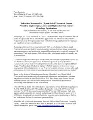
3.3.13.5. RIG Meta Data<br />
Rig SetUp<br />
Cal. Entry Meaning<br />
Details 25<br />
This screen allows calibrating and assigning all necessary data to<br />
enable the use of convergence tracking and /or retrieving the meta<br />
data of the used s3D rig.<br />
“Basic Rig Data” : This opens a sub menu entry for the input of raw IA and convergence read outs<br />
“Adj. IA zero” & “Adj. C<br />
Inf.”<br />
+/-<br />
Basic Rig SetUp ><br />
Adj. IA zero +/-[OK]<br />
Adj. C Inf. +/-[OK]<br />
Adj. Real C Dist ><br />
Limit IA to: 50.00<br />
Min. C.Dist: 2.33<br />
Lck. C to IA: on<br />
Save&Exit Cancel<br />
of the rig as well as the type of rig.<br />
: Highlight one of the topics.<br />
In case hand controller is switched off: the rig is driven to the currently stored<br />
zero/infinity positions of IA* (on mirror rig) and convergence. Drive both axis with<br />
-/+ buttons to meet requirements for a proper aligned rig (converge IA* with a<br />
close object and C with a far object on screen).<br />
In case hand controller is switched on: on: the rig is driven on demand of the hand<br />
units slider and wheel instead of the -/+ buttons. If rig is aligned, press OK button<br />
to apply current hand unit positions as zero*/infinity positions.<br />
“Min. C. Dist.:” This is a read-only entry. It shows the calculated minimum convergence distance<br />
if the unit runs in “convergence tracking” mode, which means the minimum<br />
distance the rig could converge with the maximum IA distance in order to<br />
guaranty the tracking function over the full range of the IA.<br />
“Lck. C to IA:” This switches the convergence tracking mode on or off.<br />
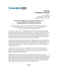
Rig Basic Settings<br />
RIG-Type<br />
Mirror<br />
Counter/Scale Readings<br />
IA min.<br />
IA max.<br />
Rev. IA Motor<br />
-20.5<br />
84.00<br />
C Ang. min<br />
C Ang. max 2.43<br />
Rev. C Motor<br />
-2.35<br />
Current Conv. Dist.<br />
Drive Conv. +/-<br />
Currt. C Dist. 14.10<br />
* On Mirror Rig only<br />
This screen allows assigning the type of rig which can be “Mirror” or “SBS” (Side by<br />
Side) as well as the basic measures for IA and Angulation with the -/+ buttons on the<br />
key pad. When high lighting one of the min. /max. values the rig is driven to the<br />
desired mechanical end stop in order to make the true readout visible on the rig as<br />
it is entered at the same time. The hand controller is disabled and has no influence<br />
when doing these adjustments.<br />
Once entered all values press OK to leave the screen.<br />
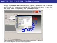
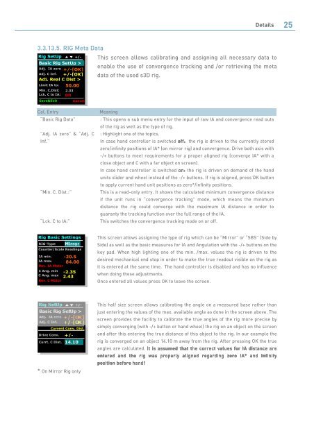
This half size screen allows calibrating the angle on a measured base rather than<br />
just entering the values of the max. available angle as done in the screen above. The<br />
screen provides the facility to calibrate the true angles of the rig more precise by<br />
simply converging (with -/+ button or hand wheel) the rig on an object on the screen<br />
and after this entering the true distance of this object to the rig. In our example the<br />
rig is converged on an object 14.10 m away from the rig. After pressing OK the true<br />
angles are calculated. It It is is assumed assumed that that the the correct correct values values for for IA IA distance distance are<br />
are<br />
entered entered and and the the rig rig was was properly properly aligned aligned regarding regarding zer zero zer o IA* IA* and and and Infinity<br />
Infinity<br />
position position before before hand hand! hand