Aladin MKII Manual Ver 1.14 - Schneider Optics
Aladin MKII Manual Ver 1.14 - Schneider Optics
Aladin MKII Manual Ver 1.14 - Schneider Optics

Create successful ePaper yourself
Turn your PDF publications into a flip-book with our unique Google optimized e-Paper software.
14 Details<br />
3.3. Receiver Menu<br />
Please note: Menu content may change with further software versions.<br />
Pressing the OK-button will enter next menu level or confirm a modification. Vise versa the<br />
ESC button moves control one level back or cancels a modification. Arrow buttons select an<br />
item and -/+ buttons modify the value of an item. Holding down + or - button for more than<br />
one second will start a loop repeating the last button event quickly. Please refer to topic<br />
3.1.6 Membrane Keypad on page 12 above.<br />
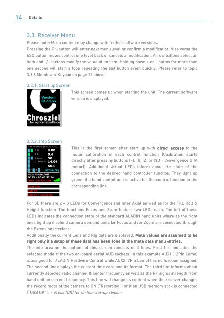
3.3.1. Start up Screen<br />
<strong>Ver</strong>sion:<br />
01.11.xx<br />
3.3.2. Info Screen<br />
Cal. Motors (F/I/Z/3D)<br />
T<br />
F m<br />
I T<br />
SETUP(OK)<br />
AUX: <strong>Aladin</strong> /Off<br />
TC 25 – 00:43:57:24<br />
Chan. 15/434.100<br />
USB OK<br />
Z mm<br />
C. Dist m<br />
R H<br />
Recording<br />
USB OK/ Recording<br />
8.00<br />
5.6<br />
50<br />
14.00<br />
50.0<br />
This screen comes up when starting the unit. The current software<br />
version is displayed.<br />
This is the first screen after start up with direct access access access to the<br />
motor calibration of each control function (Calibration starts<br />
directly after pressing buttons (F), (I), (Z) or (3D = Convergence & IA<br />
motor)). Additional virtual LEDs inform about the state of the<br />
connection to the desired hand controller function. They light up<br />
green, if a hand control unit is active for the control function in the<br />
corresponding line.<br />
For 3D there are 2 + 3 LEDs for Convergence and Inter Axial as well as for the Tilt, Roll &<br />
Height function. The functions Focus and Zoom feature two LEDs each. The left of these<br />
LEDs indicates the connection state of the standard ALADIN hand units where as the right<br />
ones light up if behind camera demand units for Focus and /or Zoom are connected through<br />
the Extension Interface.<br />
Additionally the current Lens and Rig data are displayed. Meta Meta values values are are are assumed assumed to to to be be<br />
be<br />
right right right only only if if a a setup setup of of these these data data has has been been been done done in in the the meta meta da data da ta menu entries.<br />
The info area on the bottom of this screen consists of 3 lines. First line indicates the<br />
selected mode of the two on-board serial AUX-sockets. In this example AUX1 (12Pin Lemo)<br />
is assigned for ALADIN Hardwire Control while AUX2 (7Pin Lemo) has no function assigned.<br />
The second line displays the current time code and its format. The third line informs about<br />
currently selected radio channel & center frequency as well as the RF signal strength from<br />
hand unit on current frequency. This line will change its content when the receiver changes<br />
the record mode of the camera to ON (“Recording”) or if an USB memory stick is connected<br />
(“USB OK”). - Press (OK) for further set-up steps. -