

Postprint - DTU Orbit
Postprint - DTU Orbit
Postprint - DTU Orbit

Create successful ePaper yourself
Turn your PDF publications into a flip-book with our unique Google optimized e-Paper software.
Integrated analysis of DFIG drive-train and power electronics<br />
dynamics during electrical AC faults and wind disturbances<br />
Braulio Barahona 1,* , Poul Sørensen 1 , Olimpo Anaya-Lara 2,3 and John Tande 4<br />
1) Risø <strong>DTU</strong>, Roskilde, Denmark. *Email: brab@risoe.dtu.dk<br />
2) Department of Electronic and Electrical Engineering, Institute for Energy and Environment,<br />
University of Strathclyde, Glasgow, UK.<br />
3) Department of Electrical Power Engineering, NTNU, Trondheim, Norway.<br />
4) SINTEF Energy Research, Trondheim, Norway<br />
Acknowledgments<br />
The authors would like to acknowledge NOWITECH for facilitating the collaboration between the institutions<br />
involved in the preparation of this research paper. The first author thanks the financial support<br />
from Otto Mønsteds Fond, and Risø <strong>DTU</strong> for his Ph.D. research stay at NTNU.<br />
Keywords<br />
,,,,, ,<br />
Abstract<br />
The dynamics of a 2 MW DFIG wind turbine are studied during electrical AC faults, and wind disturbances.<br />
A simulation platform that couples HAWC2, and Matlab/Simulink was used. High frequencies<br />
of the gear box, and power electronics are neglected. It was shown that the dynamics of the dc-link are<br />
influenced by turbulence, and wind gusts. An AC fault that triggers protection systems was simulated,<br />
and the influence on the dc-link voltage, shaft and tower loading illustrated.<br />
Introduction<br />
The fault ride through (FRT) capabilities of wind turbines are typically assessed disregarding aeroelastic<br />
effects, and using relatively simple structural models. Similarly, when considering the impact of wind<br />
disturbances on a wind turbine, the impact on electrical components is usually not analyzed. However,<br />
such trend is changing as an integral design is important to meet power system demands while keeping<br />
wind turbines reliable, and economic.<br />
Pursuing an integral design is a multidisciplinary task, in [1] a database of models in different specialized<br />
software is created with the vision to use it to optimize designs. However in some cases it may be relevant<br />
to analyze the global dynamics of the different subsystems of the wind turbine. Therefore, coupling or<br />
combining different specialized software [2, 3, 4, 5, 6], or further developing a given computational code<br />
[7, 8, 9] allows an integrated dynamic analysis to shed light on the dynamic interactions of different<br />
subsystems.<br />
Aeroelastic, and structural models (HAWC2) are coupled with dynamic models of the wind turbine<br />
generator, and the power system (Matlab/Simulink). The general objective is to analyze the impact of AC<br />
faults and wind disturbances on the structural, and the electrical systems of a DFIG wind turbine. Similar<br />
analysis, under an AC fault that does not trip the protection system, can be found in [2] where tower<br />
lateral acceleration, and low-speed shaft twist angle are shown to be sensitive. Furthermore, in [5, 10]<br />
it is suggested that AC faults impose prohibiting loads on the drive-train gearbox. Detail gearbox, and<br />
high-speed shaft models involve a large number of degrees of freedom, while their dominant dynamics<br />
are mainly high frequency [5]. The focus of the present work is on dynamics below 50 Hz, and the role<br />
of protection system and wind disturbances during a fault.
Simulation tools and models<br />
Wind field, aeroelastic, and mechanical components are simulated in a state-of-the-art software (HAWC2)<br />
developed at Risø <strong>DTU</strong>. The turbulence simulated in the wind field is fully 3D-coherent. Aeroelastic<br />
phenomena such as dynamic stall, and the impact of wind shear are included. The mechanical components<br />
(i.e. blades, shaft, tower) are each composed of many timoshenko beam elements. Electrical<br />
components, control, and power system are simulated in Matlab/Simulink. Technical details of HAWC2-<br />
Matlab/Simulink coupling can be found in [11, 6]. The scope is limited to the relevant dynamics in a<br />
range up to 50 Hz, disregarding very high frequencies (gearbox dynamics, and converter switching), and<br />
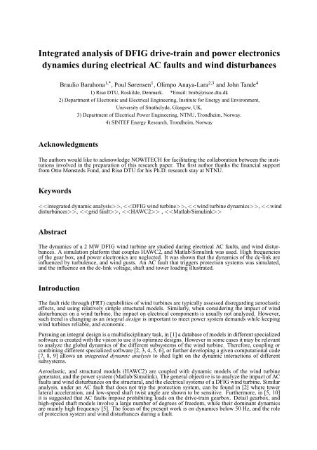
the foundation dynamics and loading. Fig. 1 illustrates the interaction of the subsystems modeled.<br />
Figure 1: Block diagram illustrating the subsystems modeled with the main variables they exchange, (blue quantities<br />
are references or measurements).<br />
HAWC2 model and blade angle control<br />
HAWC2 is based on a multibody formulation, each body consists of many timoshenko beam elements.<br />
The model is a generic 2 MW wind turbine that consists of 5 bodies: 3 blades, low-speed shaft (lss), and<br />
tower. The gear box, and high speed shaft are considered ideal. HAWC2 (red block in Fig. 1) outputs the<br />
speed at the low-speed shaftωlss to Matlab/Simulink (the rest of the blocks), and reads the blade angle<br />
θba, and electromagnetic torqueTem.<br />
The blade angle control (Fig. 2) is a deterministic adaptive control, that consists of a PI regulator with a<br />
scheduled gain [12]. The servo motor that moves the blades to set the blade angle is represented as a first<br />
order system.<br />
Power system<br />
Figure 2: Blade angle control.<br />
The power system is a double circuit transmission line supplied by an infinite bus vg. It was modeled as a<br />
(lumped-parameter) symmetrical RL-branch in dq-frame. The corresponding voltage equations are those<br />
of a 3-phase RL stationary-circuit in an arbitrary reference frame [13]. The reference frame choosen is a<br />
synchronously rotating reference frame aligned to vg (i.e. system reference frame). Once the elements
of the power system are referred to a given voltage level, the voltage equations in matrix form are given<br />
by Eq. 1. As can be interpreted from Fig. 1, Eq. 1 is solved for the voltage at the stator terminal in the<br />
system reference frame (vN). This voltage is then changed to the stator voltage vs, that is on a reference<br />
frame oriented with the generator stator flux (SFRF).<br />
vg−vN = Rgig +Lgωg +Lg ˙ ig<br />
DFIG generator<br />
The doubly-fed asynchronous generator (DFIG) consists of an asynchronous machine, dc-link, smoothing<br />
inductor, rotor-side (RSC) and grid-side converter (GSC) with their corresponding controls. The well<br />
known full-order dynamic model of asynchronous machine was implemented with flux linkages as state<br />
variables [13], in matrix form it can be expressed by Eq. 2.<br />
<br />
˙λdqs<br />
˙λdqr<br />
=M<br />
λdqs<br />
λdqr<br />
+<br />
vdqs<br />
vdqr<br />
The dynamics of the dc-link neglecting power losses [14, 15] are represented according to Eq. 3. The<br />
active powerPgsc, flowing through the smoothing inductorXsl, is calculated according to Eq. 4 based<br />
on the concept of power transfered between two sources [16].<br />
<br />
<br />
2<br />
Vdc = (Pr−Pgsc)dt (3)<br />
Cdc<br />
Pgsc = 3|vgsc||vdqs|<br />
sinδ (4)<br />
2 Xsl<br />
RSC and GSC are considered considered controllable sources, their control is implemented as generic<br />
cascade proportional-integral (PI) controls [14, 12, 17]. Fig. 3 shows these control loops, RSC controls<br />
total active powerPt, and stator reactive powerQs. GSC controls the dc-link voltageVdc, and operate<br />
= 0).<br />
the converter at unity power factor (i.e.i ref<br />
dl<br />
(a) Rotor side converter. (b) Grid side converter<br />
Figure 3: Generator control.<br />
A passive (or so called single shot) crowbar is used to protect the RSC from over currents [15]. It consists<br />
of a switch that short-circuits the rotor through an external resistance, thereby isolating the RSC. It has<br />
a duty cycle of 0.5 s, it triggers when|ir|≥2 p.u., and it removes if|vs|≈1 p.u., and if the duty cycle<br />
is met. For the reconnection of the RSC once the crowbar is removed, the RSC control is reset to avoid<br />
larger transients [14].<br />
Simulation results<br />
The cases simulated aim at analyzing the dynamics of the various subsystems of a DFIG wind turbine<br />
during an AC fault, and wind disturbances while operating at full load under nominal wind speed. First<br />
the intention is on one hand study the wind turbine structural dynamics, particularly in the drive-train (i.e.<br />
low-speed shaft) during the AC fault, while also considering the influence of wind gusts and turbulence in<br />
the dynamics of the power electronics (i.e. DC-link voltage). In the second case the role of over-current<br />
protection system of DFIG on the wind turbine structural dynamics during an AC fault is the focus.<br />
(1)<br />
(2)
|V s | [pu]<br />
wind speed [m/s]<br />
θ ba [deg]<br />
V dc [pi]<br />
18<br />
16<br />
14<br />
12<br />
10<br />
8<br />
0.5<br />
0<br />
10<br />
20<br />
60 65 70 75 80 85 90 95 100<br />
1<br />
0<br />
60 65 70 75 80 85 90 95 100<br />
10<br />
5<br />
0<br />
60 65 70 75 80 85 90 95 100<br />
(a) Wind speed, stator voltage, and blade angle.<br />
|I r | [pu]<br />
4<br />
2<br />
P [pu]<br />
M shaft [pu]<br />
ω [rad/s]<br />
1<br />
0.5<br />
0<br />
60 65 70 75 80 85 90<br />
6<br />
4 0<br />
2 10<br />
0<br />
60<br />
20<br />
65 70 75 80 85 90<br />
2.2<br />
2<br />
1.8<br />
60 65 70 75 80 85 90<br />
(b) Electrical power, moment at lss, and speed at lss.<br />
Figure 4: Case 1. Response to wind gust, turbulent wind, and AC fault.<br />
0<br />
60 65 70 75 80 85 90<br />
1.08<br />
1.06<br />
1.04<br />
1.02<br />
1<br />
0.98<br />
60 65 70 75 80 85 90<br />
T em [pu]<br />
4<br />
2<br />
0<br />
0<br />
10<br />
20<br />
60 65 70 75 80 85 90<br />
(c) Rotor current, DC voltage, and electromagnetic<br />
torque.<br />
Wind disturbances and fault<br />
T.base side M [MNm]<br />
T.top side M [MNm]<br />
5<br />
0<br />
−5<br />
60 65 70 75 80 85 90 95 100<br />
4<br />
3<br />
2<br />
1<br />
0<br />
10<br />
20<br />
0<br />
60 65 70 75 80 85 90 95 100<br />
(d) Tower base, and tower top side-to-side moments.<br />
Figure 4: Case 1. Response to wind gust, turbulent wind, and AC fault.<br />
The first simulation case Fig. 4 consists of simulations with 0%, 10%, and 20% turbulence. A 3 m/s wind<br />
gust is simulated att = 70 s. The wind gust provoques variations of the speedω in Fig. 4b (i.e. speed<br />
at low-speed shaft). These variations induce fluctuations in the power that are reflected in the DC-link<br />
voltage (Fig. 4c), however not dramatically.<br />
A symmetrical AC fault at one of the lines of the double circuit is simulated att = 80 s, the voltage<br />
drops to about 0.2 p.u., the fault is cleared after 200 ms (Fig. 4a). The crowbar external resistance is<br />
disabled, and the RSC is simply disconnected once the fault occurs. From Fig. 4b it can be seen that<br />
asωis generally fluctuating more with higher turbulence, also during the fault the fluctuations ofω<br />
are larger with higher turbulence. Evidently, the same behavior is expected from other structural and<br />
electrical variables. This can be observed from Fig. 4d in the tower side-to-side moments. However,<br />
in the electrical variables the influence of the turbulence is not so noticeable, for example in the rotor<br />
current, DC-link voltage and electromagnetic torque shown in Fig. 4c.<br />
AC fault with over-current protection<br />
In the second simulation case Fig. 5, a symmetrical AC fault in one of the lines of the double circuit<br />
is simulated att = 60 s with the same characteristics as in the previous case, while the wind is kept
|V s | [pu]<br />
V dc [V]<br />
wind speed [m/s]<br />
|I r | [pu]<br />
T em [pu]<br />
14<br />
13<br />
12<br />
11<br />
10<br />
50 55 60 65 70 75 80<br />
1<br />
0.5<br />
0<br />
50 55 60 65 70 75 80<br />
4<br />
2<br />
(a) Wind speed, and stator voltage.<br />
P [pu]<br />
M shaft [pu]<br />
ω [rad/s]<br />
1<br />
P<br />
0.5<br />
el<br />
P<br />
aero<br />
0<br />
50 55 60 65 70 75 80<br />
3<br />
2<br />
1<br />
0<br />
50 55 60 65 70 75 80<br />
M fx<br />
M mid<br />
2<br />
ω<br />
lss<br />
ω<br />
hub<br />
1.8<br />
50 55 60 65 70 75 80<br />
(b) Power, shaft moments, and speed at hub and at lss<br />
Figure 5: Case 2. Response to AC fault with over-current protection<br />
0<br />
55 60 65<br />
1.5<br />
1<br />
0.5<br />
0<br />
55 60 65<br />
3<br />
2<br />
1<br />
0<br />
−1<br />
55 60 65<br />
(c) Rotor current magnitude, DC voltage, and electromagnetic<br />
torque<br />
T.base side M [MNm]<br />
T.top side M [MNm]<br />
5<br />
0<br />
−5<br />
40 45 50 55 60 65 70 75 80<br />
3<br />
2<br />
1<br />
0<br />
−1<br />
40 45 50 55 60 65 70 75 80<br />
(d) Tower base, and tower top side-to-side moments<br />
Figure 5: Case 2. Response to AC fault with over-current protection<br />
constant. The over-current protection (i.e. passive crowbar) for the RSC triggers itself immediately after<br />
the fault, and removes once the voltage is reestablished. Fig. 5b shows on the top plot the electrical, and<br />
the aerodynamic power, the electrical power falls abruptly during the fault, while the aerodynamic power<br />
fluctuates after the fault due to the changes of electromagnetic torque that impose fluctuating loads on<br />
the shaft (Mfx andMmid in middle plot) that in turn produce changes of speedωlss, and ultimately<br />
oscillations of the hub speedωhub (bottom plot).<br />
Fig. 5c, illustrates the effect of the fault, and the role of the over-current protection in the rotor current<br />
|Ir|, dc-link voltageVdc, and electromagnetic torqueTem. Namely, it can be observed howVdc responds<br />
after the fault, once the protection is removed. Fig. 5d shows that the loads on tower top side-to-side<br />
moment during the fault, and the removal of the protection can reach relatively high maximum values.<br />
Conclusions and further work<br />
The dynamics of structural, and electrical subsystems of a DFIG wind turbine were simulated with<br />
HAWC2-Matlab/Simulink. The influence of wind disturbances on the dc-link voltage of the power electronics<br />
was illustrated with simulations of turbulent wind, and a wind gust, while the dc-link voltage is<br />
sensible such disturbances, the simulations showed that this influence in not dramatic. However, this is<br />
very dependent on the dimensions of the system, and the design of the control, therefore a parametric<br />
study would yield more general results for this wind turbine topology.
The influence of electrical disturbances was also illustrated. For example, simulations showed the mechanical<br />
loads imposed on the low-speed shaft during the fault, it was observed that the removal of the<br />
over-current protection may impose relatively large loading on the tower top side-to-side moment. This is<br />
however, dependent on how the electromagnetic torque fluctuations transferred through the speed/torque<br />
of the generator rotor are propagated through the nacelle and into the tower,the simulations presented<br />
here represent a worst case.<br />
References<br />
[1] F. Iov, A. D. Hansen, P. Sørensen, and F. Blaabjerg, “Simulation platform to model, optimize and design<br />
wind turbines,” Tech. Rep. ISBN 87-89179-45-5, Aalborg University and Risø National Laboratory, 2004.<br />
[2] R. Fadaeinedjad, M. Moallem, and G. Moschopoulos, “Simulation of a wind turbine with doubly fed induction<br />
generator by fast and simulink,” IEEE Transactions on Energy Conversion, vol. 23, pp. 690–700,<br />
2008.<br />
[3] F. M. Huges, O. Anaya-Lara, G. Ramtharan, N. Jenkins, and G. Strbac, “Influence of Tower Shadow and<br />
Wind Turbulence on the Performance of Power System Stabilizers for DFIG-Based Wind Farms,” IEEE<br />
Transactions on Energy Conversion, vol. 23, pp. 519–528, 2008.<br />
[4] A. D. Hansen, N. A. Cutululis, H. Markou, and P. Sørensen, “Impact of fault ride-through requirements on<br />
fixed-speed wind turbine structural loads,” Wind Energy, 2010.<br />
[5] J. Sanz-Corretge, A. García-Barace, and I. Egaña, “Load transient analysis of wind turbine drive train under<br />
grid disturbances,” in European Wind Energy Conference, 2010.<br />
[6] B. Barahona, L. C. Henriksen, A. D. Hansen, N. A. Cutululis, and P. Sørensen, “Coupling of HAWC2 and<br />
Matlab: Towards an Integrated Simulation Platform,” in European Wind Energy Conference, April 2010.<br />
[7] A. Heege, Y. Radovcic, and J. Betran, “Fatigue load computation of wind turbine gearboxes by coupled<br />
structural, mechanism and aerodynamic analysis,” DEWI Magazin, vol. 28, pp. 61 – 68, 2006.<br />
[8] G. Ramtharan, N. Jenkins, O. Anaya-Lara, and E. Bossanyi, “Influence of rotor structural dynamics representations<br />
on the electrical transient performance of fsig and dfig wind turbines,” Wind Energy, vol. 10,<br />
pp. 293–301, March 2007.<br />
[9] G. Ramtharan, N. Chris, and B. Ervin, “Importance of advanced simulations of electrical transients in wind<br />
turbines,” in European Wind Energy Conference, April 2010.<br />
[10] D. Aguglia and R. Rebeschini, “Power transformer role for gearbox mechanical stress mitigation during<br />
voltage dips applied to doubly-fed induction generator based wind turbines,” in European Wind Energy Conference,<br />
2010.<br />
[11] B. Barahona, P. B. Adersen, A. D. Hansen, N. A. Cutululis, and P. Sørensen, “Integrated design of wind<br />
power systems: MATLAB-HAWC2 interface,” in 50th International Conference of Scandinavian Simulation<br />
Society (SIMS 50), 2009.<br />
[12] A. D. Hansen and G. Michalke, “Fault ride-through capability of DFIG wind turbines,” Renewable Energy,<br />
vol. 32, pp. 1594 – 1610, December 2006.<br />
[13] P. C. Krause, O. Wasynczuk, and S. D. Sudhoff, Analysis of Electric Machinery and Drive Systems. IEEE<br />
Press Series on Power Engineering, WileyBlackwell, 2002.<br />
[14] V. Akhmatov, Analysis of Dynamic Behaviour of Electric Power Systems with Large Amount of Wind Power.<br />
PhD thesis, Technical University of Denmark, 2003.<br />
[15] O. Anaya-Lara, N. Jenkins, J. Ekanayake, P. Cartwright, and M. Huges, Wind Energy Generation: Modelling<br />
and Control. Wiley, 2009.<br />
[16] P. Kundur, Power System Stability and Control. McGraw-Hill, 1994.<br />
[17] G. Michalke, Variable Speed Wind Turbines - Modelling, Control and Impact on Power Systems. PhD thesis,<br />
Darmstadt Technical University, 2008.


