1 KOZENY-CARMAN EQUATION REVISITED Jack Dvorkin -- 2009 ...
1 KOZENY-CARMAN EQUATION REVISITED Jack Dvorkin -- 2009 ...
1 KOZENY-CARMAN EQUATION REVISITED Jack Dvorkin -- 2009 ...

You also want an ePaper? Increase the reach of your titles
YUMPU automatically turns print PDFs into web optimized ePapers that Google loves.
€<br />
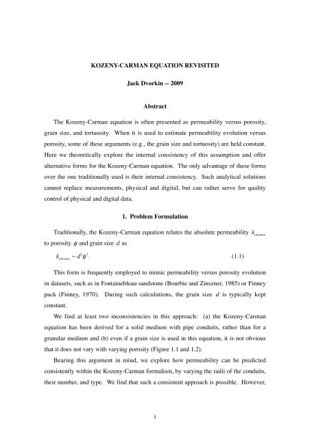
<strong>KOZENY</strong>-<strong>CARMAN</strong> <strong>EQUATION</strong> <strong>REVISITED</strong><br />
<strong>Jack</strong> <strong>Dvorkin</strong> -- <strong>2009</strong><br />
Abstract<br />
The Kozeny-Carman equation is often presented as permeability versus porosity,<br />
grain size, and tortuosity. When it is used to estimate permeability evolution versus<br />
porosity, some of these arguments (e.g., the grain size and tortuosity) are held constant.<br />
Here we theoretically explore the internal consistency of this assumption and offer<br />
alternative forms for the Kozeny-Carman equation. The only advantage of these forms<br />
over the one traditionally used is their internal consistency. Such analytical solutions<br />
cannot replace measurements, physical and digital, but can rather serve for quality<br />
control of physical and digital data.<br />
1. Problem Formulation<br />
Traditionally, the Kozeny-Carman equation relates the absolute permeability<br />
to porosity φ and grain size d as<br />
kabsolute ~ d<br />
€<br />
2 φ 3 . (1.1)<br />
1<br />
k absolute<br />
€<br />
€<br />
This form is frequently employed to mimic permeability versus porosity evolution<br />
in datasets, such as in Fontainebleau sandstone (Bourbie and Zinszner, 1985) or Finney<br />
pack (Finney, 1970). During such calculations, the grain size<br />
constant.<br />
d is typically kept<br />
We find at least two inconsistencies in this approach: (a) the Kozeny-Carman<br />
€<br />
equation has been derived for a solid medium with pipe conduits, rather than for a<br />
granular medium and (b) even if a grain size is used in this equation, it is not obvious<br />
that it does not vary with varying porosity (Figure 1.1 and 1.2).<br />
Bearing this argument in mind, we explore how permeability can be predicted<br />
consistently within the Kozeny-Carman formalism, by varying the radii of the conduits,<br />
their number, and type. We find that such a consistent approach is possible. However,
it requires additional assumptions, specifically, regarding tortuosity evolution during<br />
porosity reduction.<br />
In the end we arrive at alternative forms for the Kozeny-Carman equation, which<br />
still should not be used to predict permeability, but instead to quality-controls physical<br />
and digital experimental data.<br />
0.250<br />
0.109<br />
2<br />
0.167<br />
0.072<br />
Figure 1.1. Cross-sections of four Fontainebleau sandstone samples with decreasing porosity (posted<br />
on top of each image). The scale bar in each image is 0.5 mm. We argue that it is not obvious which<br />
parameters (grain size, conduit size, or the number of conduits) change during porosity reduction.
Figure 1.2. Cross-sections of a Finney pack for uniformly increasing radius of each sphere (from<br />
1.00 to 1.45 mm with 0.05 mm increment, left to right and top to bottom) and respectively decreasing<br />
porosity (posted on top of each image). As in the images in Figure 1.1, it is not immediately obvious<br />
which parameters (grain size, conduit size, or the number of conduits) change during porosity<br />
reduction.<br />
3
€<br />
€<br />
€<br />
€<br />
€<br />
€<br />
€<br />
€<br />
€<br />
The definition of absolute permeability<br />
equation (e.g., Mavko et al., 1998)<br />
where<br />
2. Definition of Absolute Permeability<br />
A dP<br />
Q = −k €<br />
absolute , (2.1)<br />
µ dx<br />
Q is the volume flux through the sample (in, e.g., m 3 /s);<br />
area of the sample (in, e.g., m 2 );<br />
4<br />
k absolute of porous rock comes from Darcy’s<br />
A is the cross-sectional<br />
µ is the dynamic viscosity of the fluid (in, e.g., Pa s<br />
with 1 cPs = 10<br />
€<br />
€<br />
-3 Pa s); and dP /dx is the pressure drop across the sample divided by the<br />
length of the sample (in, e.g., Pa/m).<br />
where<br />
€<br />
3. Flow Through a Circular Pipe<br />
The equation for laminar viscous flow in a pipe of radius b is<br />
∂<br />
€<br />
2 u 1 ∂u 1 dP<br />
+ = , (3.1)<br />
2<br />
∂r r ∂r µ dx<br />
of the fluid;<br />
u is the velocity of the fluid in the axial ( x) direction; µ is the dynamic viscosity<br />
dP /dx is the pressure gradient in the axial direction; and<br />
r and<br />
radial and axial coordinates, respectively.<br />
€<br />
A general solution of Equation (3.1) is<br />
€<br />
€<br />
€ €<br />
u = ˜ A + ˜ B r 2 + ˜ C ln r, (3.2)<br />
where<br />
€<br />
∂u<br />
∂r<br />
˜<br />
A ,<br />
˜<br />
B , and<br />
˜<br />
C are constants. It follows from Equation (3.2) that<br />
= 2C ˜ r +<br />
€<br />
˜ C<br />
r , ∂ 2 u<br />
= 2C ˜ − 2<br />
∂r ˜ C<br />
. (3.3)<br />
2<br />
r<br />
x are the<br />
By substituting the expressions from Equation (3.3) into Equation (3.1) we find that<br />
2 ˜ B − ˜ C<br />
+ 2B ˜ + 2<br />
r ˜ C 1 dP<br />
= , (3.4)<br />
2<br />
r µ dy<br />
which means that<br />
B ˜ = 1 dP<br />
. (3.5)<br />
4µ dx
€<br />
€<br />
€<br />
€<br />
€<br />
€<br />
€<br />
€<br />
€<br />
To avoid singularity at<br />
Next, we will employ the no-slip condition<br />
r = 0 we need to assume that in Equation (3.2)<br />
u = €<br />
€<br />
€ € €<br />
˜ A + ˜ B r 2 = ˜ A + 1 dP<br />
4µ dx r 2 = ˜ A + 1 dP<br />
4µ dx b2 = 0, (3.6)<br />
which means<br />
and<br />
where<br />
A ˜ = − 1 dP<br />
4µ dx b2<br />
5<br />
u = 0 at<br />
r = b.<br />
˜<br />
C = 0.<br />
(3.7)<br />
u = − 1 dP<br />
4µ dx b2 2<br />
r<br />
(1− ). (3.8)<br />
2<br />
b<br />
The total volume flux through the pipe is<br />
q = − πb4<br />
8µ<br />
ΔP<br />
, (3.9)<br />
l<br />
l is the length of the pipe,<br />
and the pressure gradient<br />
ΔP is the pressure head along the length of the pipe,<br />
dP /dx is replaced with<br />
ΔP /l.<br />
4.<br />
€<br />
Absolute Permeability – Round Pipe<br />
€<br />
€<br />
Assume that a pore space is made of N identical parallel round pipes embedded in a<br />
solid block at an angle α to its horizontal face (Figure 4.1). The horizontal pressure<br />
head across the block is ΔP . The length of each pipe inside the block is<br />
€<br />
where<br />
l = L /sinα € = Lτ, (4.1)<br />
tortuosity.<br />
L is the<br />
€<br />
horizontal length of the block and, by definition, τ = sin −1 α is the<br />
Using Equations (3.9) and (4.1), we obtain the total flux through N pipes as<br />
€<br />
where<br />
Q = Nq = −N πb4 ΔP πb4 dP<br />
= −N<br />
8µ Lτ 8µτ dx = −Nπb2τ b2<br />
8µτ 2<br />
ΔP /Lτ is the pressure gradient across the pipe.<br />
The porosity of the block due to the pipes is<br />
dP<br />
, (4.2)<br />
dx<br />
€
€<br />
€<br />
€<br />
€<br />
€<br />
€<br />
€<br />
€<br />
where<br />
φ = Nπb2l AL = Nπb2τ , (4.3)<br />
A<br />
A is the cross-sectional area of the block, same as used in Equation (2.1).<br />
Figure 4.1. Solid block with a pipe used for Kozeny-Carman derivations (left). Notations are<br />
explained in the text. To the right, we show a cross-section of an open pipe and that of the same pipe<br />
with a concentric solid kernel.<br />
By combining Equations (4.2) and (4.3), we obtain<br />
Q = −φ b2<br />
8τ 2<br />
A<br />
µ<br />
dP<br />
, (4.4)<br />
dx<br />
which means (using the definition of absolute permeability) that<br />
area<br />
k = b absolute 2 φ<br />
. (4.5)<br />
2<br />
8τ<br />
Let us next introduce another characteristic of the pore space, the specific surface<br />
s, which, by definition, is the ratio of the pore surface area to the total volume of<br />
the block. For the block permeated by pipes,<br />
s = N2πbl<br />
AL<br />
and, therefore,<br />
= N2πbτ<br />
A<br />
b = 2φ /s and<br />
= Nπb2τ 2<br />
A b<br />
2φ<br />
= . (4.6)<br />
b<br />
kabsolute =<br />
€<br />
1 φ<br />
2<br />
3<br />
s 2 . (4.7)<br />
2<br />
τ<br />
Finally, let us combine Equations (2.1) and (4.2) to obtain<br />
kabsolute = N πb<br />
Aτ<br />
4<br />
. (4.8)<br />
8<br />
6
€<br />
€<br />
€<br />
5. Absolute Permeability -- Concentric Pipe<br />
Consider fluid flow through a round pipe of radius<br />
of radius<br />
inside the annular gap formed by the pipe and kernel. The solution for velocity u inside<br />
€<br />
the annular gap is obtained from Equation (3.2) and using the no-slip ( u = 0) boundary<br />
€<br />
conditions at r = b and r = a:<br />
€<br />
7<br />
€<br />
b with a concentric solid kernel<br />
a inside (Figure 4.1). Equations (3.1) and (3.2) are still valid for the flow<br />
u = −<br />
€<br />
€ € € €<br />
1 dP<br />
4µ dx b2 2<br />
r a2 ln(b /r)<br />
[(1− ) − (1− ) ]. (5.1)<br />
2 2<br />
b b ln(b /a)<br />
A comparison of the radial velocity field according to Equation (5.1) and (3.8) is<br />
displayed in Figure 5.1.<br />
Figure 5.1. Normalized velocity of fluid versus the normalized radius of a circular pipe for (a) flow<br />
in a circular pipe without a kernel and (b) annular floe in a pipe with a kernel for the radius of the<br />
kernel 0.1 of that of the pipe.<br />
By integrating the right-hand part of this equation times<br />
respect to<br />
€<br />
r we obtain the flux through the annular gap:<br />
q = − π ΔP<br />
8µ l b4 (1− a2<br />
b<br />
2 )[1+ a2<br />
a2<br />
+ (1− 2<br />
b b<br />
Let us remember that for a pipe without a kernel,<br />
2 )<br />
2πr from<br />
a to<br />
1<br />
]. € € €<br />
(5.2)<br />
ln(a /b)<br />
q = − πb4 ΔP<br />
. (5.3)<br />
8µ l<br />
We can arrive at this expression from Equation (5.2) if<br />
a = 0 and lna → −∞.<br />
€<br />
b and with
€<br />
€<br />
€<br />
€<br />
Also, if<br />
a → b, the infinity in the denominator of the third term in the square<br />
brackets in Equation (5.2) has the same order as that in the numerator, and<br />
In Figure 5.2 we display the ratio ξ of the flux computed according to Equation<br />
€<br />
(5.2) to that according to Equation (5.3):<br />
€<br />
ξ = (1− €<br />
a2 a2 a2 1<br />
)[1+ + (1− ) ], 2 2 2<br />
b b b ln(a /b)<br />
(5.4)<br />
which behaves predictably.<br />
8<br />
q → 0.<br />
Figure 5.2. Ratio of annular flux to that through a round pipe versus the normalized radius of a<br />
kernel.<br />
The total flux through<br />
Q = Nq = −N<br />
€<br />
π ΔP<br />
8µ<br />
N pipes with a kernel is<br />
Lτ b4 (1− a2 a2<br />
)[1+ 2<br />
b b<br />
Hence the absolute permeability is<br />
kabsolute = N πb<br />
Aτ<br />
4<br />
8<br />
(1− a2<br />
b<br />
2 )[1+ a2<br />
The porosity of this block is now<br />
φ = Nπ(b2 − a 2 )l<br />
AL<br />
The specific surface area is<br />
a2<br />
+ (1− 2<br />
b b<br />
a2<br />
+ (1− 2<br />
b<br />
2 )<br />
2 )<br />
1<br />
]. (5.5)<br />
ln(a/b)<br />
1<br />
]. (5.6)<br />
ln(a/b)<br />
= Nπ(b2 − a 2 )τ<br />
. (5.7)<br />
A
€<br />
€<br />
€<br />
s =<br />
N2π(b + a)l<br />
AL<br />
As a result,<br />
k absolute = φ<br />
= N2π(b + a)τ<br />
8τ 2 b2 [1+ a2<br />
b<br />
A<br />
a2<br />
+ (1− 2<br />
b<br />
2 )<br />
= Nπ(b2 − a 2 )τ<br />
A<br />
9<br />
2<br />
b − a<br />
2φ<br />
= . (5.8)<br />
b − a<br />
1<br />
]. (5.9)<br />
ln(a /b)<br />
6. Permeability versus Porosity<br />
Within the above formalism, one may envision at least three porosity variation<br />
scenarios: (a) the number of the pipes<br />
N varies, (b) the number<br />
N remains constant,<br />
but the radius of the pipes b varies, and (c) the number N remains constant and so does<br />
the radius of the pipes b, but concentric kernels of radius a grow inside the pipes<br />
€<br />
€<br />
(Figure 6.1).<br />
€<br />
€<br />
€<br />
Original Block Porosity Reduces with<br />
the Number of Pipes<br />
€<br />
Porosity Reduces with<br />
the Radius of Pipes<br />
Porosity Reduces with the<br />
Radius of Kernels<br />
Figure 6.1. Porosity reduction from that of the original block (left) by the reduction of the number of<br />
the pipes (middle), the radius of a pipe (third to the right), and radius of the kernels.<br />
Consider a solid block with a square cross-section with a 10 -3 m side and the<br />
resulting cross-sectional area<br />
pipes with radius<br />
A = 10 -6 m 2 . It is penetrated by<br />
b = 2.83·10 -5 m. Also assume<br />
N = 50 identical round<br />
τ = 2.5. The resulting porosity is φ =<br />
Nπb<br />
€<br />
€<br />
€<br />
€<br />
€<br />
2 τ / A = 0.30. The resulting permeability, according to Equation (4.8), is k =<br />
absolute<br />
4.772·10<br />
€<br />
-5 m 2 = 4772 mD.<br />
Next, we alter the original block (left image in Figure 6.1) according to the proposed<br />
three porosity reduction scenarios. The results are shown in Figure 6.2, where we also<br />
display the classical Fontainebleau sandstone data as well as data for North Sea sand<br />
(Troll field). This figure also explains our choice of the solid block and pipe parameters<br />
earlier in this section – the numbers selected helped match the porosity and permeability
€<br />
€<br />
of the original block to those of the highest-porosity Fontainebleau sample.<br />
Figure 6.2. Permeability versus porosity according to scenarios a, b, and c. Open symbols are for<br />
measured permeability in Fontainebleau sandstone. Filled symbols are for measured permeability in<br />
sand samples from Troll field offshore Norway.<br />
Figure 6.2 also indicates that none of the proposed simple models reproduces the<br />
trends present in real data.<br />
7. Third Dimension and Tortuosity<br />
Modeling rock as a block with fixed cross-section, clearly does not produce<br />
permeability results that match laboratory data. Let us hypothesize that the effect of the<br />
third dimension can be modeled by varying the tortuosity<br />
Kozeny-Carman formalism, let us assume that τ varies with porosity φ.<br />
Consider two candidate equations for this dependence:<br />
€<br />
10<br />
τ . Specifically, within the<br />
τ = φ €<br />
€<br />
−1.2 , (7.1)<br />
derived from laboratory contaminant diffusion experiments by Boving and Grathwohl<br />
(2001) and<br />
τ = (1+ φ −1 ) /2, (7.2)<br />
theoretically derived by Berryman (1981).
€<br />
€<br />
€<br />
€<br />
At φ = 0.3, these two equations give τ = 4.24 and 2.17, respectively.<br />
Let us next repeat out calculations of permeability for the three porosity evolution<br />
scenarios, but this time with the tortuosity varying versus porosity. Also, to keep the<br />
€<br />
scale consistent, we will scale Equations (7.1) and (7.2) to yield τ = 2.5 at φ = 0.3 as<br />
follows<br />
and<br />
τ = 0.590φ −1.2<br />
11<br />
€<br />
€<br />
(7.3)<br />
τ = 0.576(1+ φ −1 ). (7.4)<br />
The results shown in Figure 7.1 indicate that both the above equations produce<br />
similar results. Permeability calculated for porosity reduction scenario with contracting<br />
pipe size matches the Fontainebleau data in the medium-to-high porosity range but fails<br />
for low porosity.<br />
Figure 7.1. Permeability versus porosity according to scenarios a, b, and c with varying tortuosity.<br />
Left, according to Equation (7.3) and right, according to Equation (7.4).<br />
Our final attempt to match the Fontainebleau data is to assume that the tortuosity<br />
becomes infinity at some small percolation porosity<br />
1997). The resulting equations for tortuosity become<br />
τ = 0.590(φ − φ p ) −1.2<br />
€<br />
φ p (following Mavko and Nur,<br />
(7.5)
€<br />
€<br />
€<br />
€<br />
and<br />
τ = 0.576[1+ (φ − φ p ) −1 ]. (7.6)<br />
The resulting permeability curves for the case of shrinking pipes and φ p = 0.025 are<br />
displayed in Figure 7.2. This final match appears to be satisfactory.<br />
Figure 7.2. Permeability versus porosity for shrinking pipes and for tortuosity given by Equation<br />
(7.4) – top curve, Equation (7.5) – middle curve, and Equation (7.6) – bottom curve.<br />
The resulting forms of the Kozeny-Carman equation obtained by combining<br />
Equations (4.5) and (4.7) with Equation (7.6) are, respectively,<br />
and<br />
k absolute = 0.357b 2<br />
k absolute =1.507s −2<br />
φ<br />
[1+ (φ − φ p) −1 ] 2<br />
12<br />
€<br />
(7.7)<br />
φ 3<br />
[1+ (φ − φ p ) −1 . (7.8)<br />
2<br />
]<br />
Some other reported relations between τ and φ are:<br />
τ = 0.67φ −1 , (7.9)<br />
€<br />
theoretically derived based on the assumption € of fractal pore geometry (Pape et al.,<br />
1998) and
€<br />
€<br />
τ =1.8561− 0.715φ, 0.1 < φ < 0.5;<br />
τ = 2.1445 −1.126φ, 0.3 < φ < 0.5;<br />
τ = −2.1472 + 5.244φ, 0.6 < φ
€<br />
€<br />
€<br />
€<br />
€<br />
space is<br />
4Mπr 2 . Therefore, for this specific case,<br />
s = 3(1− φ 0 ) /r = 6(1− φ 0 ) /d, (8.2)<br />
€<br />
where d = 2 r.<br />
Note that this equation is only valid for a sphere pack with porosity<br />
we assume that the same equation applies to the entire porosity range, which is clearly<br />
€<br />
invalid since s should be generally decreasing with decreasing porosity, we obtain form<br />
€<br />
Equations (8.1) and (8.2)<br />
2<br />
€ r φ<br />
k = absolute<br />
18<br />
3<br />
(1− φ) 2 2<br />
d φ<br />
= 2<br />
τ 72<br />
3<br />
(1− φ) 2 , (8.3)<br />
2<br />
τ<br />
where<br />
d = 2 r.<br />
(Mavko and Nur, 1997) as<br />
€<br />
14<br />
φ 0 ≈ 0.36. If<br />
We can also modify this last equation by introducing a percolation porosity<br />
k absolute =<br />
2<br />
d (φ − φ p)<br />
€<br />
72<br />
3<br />
(1− φ + φ ) p 2 , (8.4)<br />
2<br />
τ<br />
The corresponding curve for<br />
€<br />
φ p = 0.025,<br />
tortuosity τ = 0.25 is plotted in Figure 8.1.<br />
€<br />
€<br />
φ p<br />
d = 0.25 mm = 0.00025 m, and constant<br />
Figure 8.1. Black curve: permeability versus porosity for shrinking pipes with the tortuosity given<br />
by Equation (7.6). Red curve: permeability versus porosity according to Equation (8.4) with<br />
parameters described in the text.
9. Conclusion<br />
Consistency is possible in deriving and applying Kozeny-Carman equation for<br />
permeability as a function of porosity. Any such derivation inherently requires such<br />
idealized and, generally, nonexistent in real rock parameters as grain size, pore size, and<br />
tortuosity. Yet, the Kozeny-Carman equation can be made to mimic some experimental<br />
trends and, therefore, serve as a quality-control tool for physical and digital<br />
experimental results.<br />
References<br />
Berryman, J.G., 1981, Elastic wave propagation in fluid-saturated porous media,<br />
Journal of Acoustical Society of America, 69, 416-424.<br />
Bourbie, T., and Zinszner, B., 1985, Hydraulic and acoustic properties as a function of<br />
porosity in Fontainebleau Sandstone, Journal of Geophysical Research, 90, 11,524-<br />
11,532.<br />
Boving, T.B., and Grathwohl, P., 2001, Tracer diffusion coefficients in sedimentary<br />
rocks: correlation to porosity and hydraulic conductivity, Journal of Contaminant<br />
Hydrology, 53, 85-100.<br />
Finney, J., 1970, Random packing and the structure of simple liquids (The geometry of<br />
random close packing), Proceedings of the Royal Society, 319A, 479.<br />
Mavko, G., and Nur, A., 1997, The effect of a percolation threshold in the Kozeny-<br />
Carman relation, Geophysics, 62, 1480-1482.<br />
Pape, H., Clauser, C., and Iffland, J., 1998, Permeability prediction for reservoir<br />
sandstones and basement rocks based on fractal pore space geometry, SEG<br />
Expanded Abstracts, SEG 1998 Meeting.<br />
Salem, H., and Chilingarian, G.V., 2000, Influence of porosity and direction of flow on<br />
tortuosity in unconsolidated porous media, Energy Sources, 22, 207-213.<br />
15
€<br />
Appendix: Specific Surface Area of the Finney Pack with Expanding Spheres<br />
We select a cubic subset of the Finney pack and gradually and uniformly expand the<br />
radius of each sphere from 1 to 1.5 mm. The evolution of the porosity of these packs<br />
versus the radius of a sphere is shown in Figure A.1.<br />
Figure A.1. Left – porosity of a Finney pack decreasing with the increasing radius of each sphere.<br />
Middle – the specific surface area decreasing with the increasing radius of each sphere. Right – the<br />
specific surface area increasing with increasing porosity (black). The red curve is computed from<br />
Equation (A.1) with fixed sphere radius 1 mm. The blue curve is also computed from Equation (A.1)<br />
but with respectively increasing sphere radius.<br />
In the same figure we display the calculated specific surface area versus the radius<br />
and the specific surface area versus the porosity. In the latter frame, we also display a<br />
theoretical curve according to equation<br />
s = 3(1− φ) /r (A.1)<br />
for varying porosity and fixed radius<br />
€<br />
r = 1 and for varying porosity and varying radius.<br />
Neither of these two theoretical curves even qualitatively matches the computed specific<br />
surface area.<br />
16