Multiport vector network analyzer calibration: a general formulation ...
Multiport vector network analyzer calibration: a general formulation ...
Multiport vector network analyzer calibration: a general formulation ...

You also want an ePaper? Increase the reach of your titles
YUMPU automatically turns print PDFs into web optimized ePapers that Google loves.
IEEE TRANSACTIONS ON MICROWAVE THEORY AND TECHNIQUES, VOL. 42, NO. 12, DECEMBER 1994 2455<br />
<strong>Multiport</strong> Vector Network Analyzer<br />
Calibration: A General Formulation<br />
Andrea Ferrero, Member, IEEE, Fernando Sanpietro, and Umberto Pisani<br />
Abstruct- An overall <strong>calibration</strong> theory for <strong>Multiport</strong> Net-<br />
work Analyzers (MNWA) is presented. A <strong>general</strong> algorithm is<br />
developed to exploit the redundancy inherent in MNWA self-<br />
<strong>calibration</strong>. Linear dependency conditions given by using one-<br />
port or two-port standards to calibrate a MNWA are analyzed,<br />
by deriving novel criteria for multiport self-<strong>calibration</strong>. It is<br />
theoretically and experimentally demonstrated that an n-port test<br />
set can be calibrated by using only one two-port standard and<br />
one load. The excellent accuracy reached by means of this new<br />
theory opens new alternatives to a metrological qualification of<br />
MNWA for n-port device testing.<br />
I. INTRODUCTION<br />
ULTIPORT <strong>network</strong> <strong>analyzer</strong> <strong>calibration</strong> has been re-<br />
n!t cently studied by several authors to extend usual <strong>calibration</strong><br />
algorithms, developed for 2-port <strong>network</strong> <strong>analyzer</strong> to<br />
n-port port test set [l], [21. References [3], [4] suggested<br />
extension of the through-short-delay (TSD) technique to a<br />
<strong>general</strong> n-port, taking into account the errors due to signal<br />
leakage between port pairs. The test set <strong>calibration</strong> was carried<br />
out by means of three n-port standards. Another technique [5]<br />
is based on several partial two-port measurements properly<br />
combined to account for the mismatch errors of the other n - 2<br />
ports; this technique is practically unrealizable when devices<br />
with more than three ports are considered due to the large<br />
amount of 2-port measurements to be performed.<br />
More recently, the authors and others introduced a new<br />
solution for a true multiport lest set hardware and a <strong>calibration</strong><br />
technique which used commercially available one or two-port<br />
standards [l]. In that paper, an iterative procedure for the<br />
standard connections was used but the potential to reduce the<br />
number of measurements by redundancy in an wport system<br />
was not considered.<br />
A novel formal approach to the MNWA <strong>calibration</strong> problem,<br />
which exploits the self-<strong>calibration</strong> capabilities of the test set<br />
was introduced by the authors earlier [6], where an inclusive<br />
analysis was carried out and the case of a 3-port <strong>network</strong><br />
<strong>analyzer</strong> was presented.<br />
Here we <strong>general</strong>ize the concept outlined there by introducing<br />
a <strong>general</strong> equation which links the scattering parameters<br />
of standards or unknown devices and their corresponding<br />
measurements to a suitable set of error coefficients.<br />
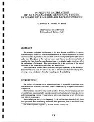
Manuscnpt received April I, 1994; revised July 11, 1994. This work was<br />
supported in part by the National Research Council of Italy (CNR) and in part<br />
by Hewlett-Packard of Italy.<br />
The authors are with Department of Electronics, Politecnico di Torino,<br />
Corso Duca degli Abruzzi 24, 10129 Torino, Italy.<br />
IEEE Log Number 9405432<br />
001 8-9480/94$04.00 0 1994 IEEE<br />
Fig. 1. Generalized model of a multiport test-set.<br />
The <strong>calibration</strong> problem is unified from a mathematical<br />
point of view and it can be treated by solving a linear system<br />
built in a straightforward manner from measurements. Any<br />
combination of standards can be used, provided that the equa-<br />
tions generated by their measurements produce enough linear<br />
independent equations to evaluate all the error coefficients.<br />
This paper presents the theoretical criteria needed to com-<br />
bine enough standard measurements into a consistent linear<br />
system and consequently to define a consistent <strong>calibration</strong><br />
procedure. The user is free to best fit the particular application,<br />
taking advantage of the excess of measurement achievable by<br />
manifold test ports.<br />
The paper is organized as follows: a <strong>general</strong> de-embedding<br />
formula for an n-port <strong>network</strong> <strong>analyzer</strong> is derived in Sec-<br />
tion 11; a <strong>general</strong> equation to solve the <strong>calibration</strong> prob-<br />
lem is given in Section 111; an analysis of linear indepen-<br />
dance conditions which are imposed by one or two-port<br />
standards used to calibrate a MNWA is presented in Section<br />
IV; and finally, some experimental results are presented in<br />
Section V.<br />
11. MULTIPORT DE-EMBEDDING FORMULATION<br />
An actual MNWA, after a proper switch correction proce-<br />
dure detailed in [l], can be seen as an error-free NWA which<br />
measures the raw scattering matrix S, and a set of n 2-port<br />
<strong>network</strong>s, i.e., the error boxes, which tie the ideal NWA to the<br />
DUT as shown in Fig. 1.<br />
Each error box is defined by a pseudo-scattering matrix E;,<br />
where i = 1, . . . , n:
2456 IEEE TRANSACTIONS ON MICROWAVE THEORY AND TECHNIQUES, VOL. 42, NO. 12, DECEMBER 1994<br />
In a multiport system the error coefficients become elements<br />
of four diagonal matrices r;j:<br />
0 roo = diag(e?', . . . , e:", . . . ,e, 00 )<br />
0 rOl = diag(e;l, . . . , . . , e:)<br />
0 rlo = diag(efO,. . . ! eto,. . . !e:')<br />
0 rll = diag(eil, . . . ,e:', . . . ,e,<br />
11 ).<br />
After some matrix algebra, detailed in [1], it results<br />
s, = roo + rolp - srll]-lsrlo<br />
where I is the n-dimensional unitary matrix and S is the<br />
scattering matrix of the multiport device under test.<br />
Equation (3) can be written in the form<br />
or<br />
rol-lsmi'lu-l - srllrol -lsmrl0-l - rol-lroorlo-l<br />
+ srllrol-lroorlo-l = s. (5)<br />
By introducing<br />
(2)<br />
(3)<br />
A = rooI'11 - rolrlo (6)<br />
We note that A iS also a diagonal matrix; in the following each<br />
element of its diagonal is annotated as A, (z = 1 . . .n).<br />
By rearranging (5) we obtain<br />
rol-ls,rlo-l - srllrol-ls,rlo-l - rol-lroorlo-l<br />
+ sarol-lrlo-l = 0.<br />
Define the diagonal matrix I( as<br />
Equation (7) becomes<br />
K = e?lI'ol-'.<br />
The goal of a selected <strong>calibration</strong> procedure is to compute<br />
K, roo, rll, and A, from a proper set of standard <strong>network</strong><br />
measurements.<br />
111. GENERAL THEORY OF CALIBRATION<br />
Matrix equation (9), can be also seen as n2 equations of<br />
the form<br />
(2 = 1, . . . ,n)<br />
(j=1 ,..., 7L)<br />
where 6,, is the kronecker symbol (6,, = 1 if a = j otherwise<br />
S, = 0) and A,, = = eY1/e:l (z = 1.. . . ,71). Equation<br />
(1 1) is a <strong>general</strong> relationship which links error coefficients,<br />
standard or DUT parameters S,, and their corresponding<br />
measurements SmzJ. This equation can be applied to each<br />
(7)<br />
standard measurement regardless the number of standards or<br />
their connections. It is also linear in a proper set of error<br />
coefficients.<br />
Since IC1 sf 1, there are (4n- 1) global unknowns and these<br />
can be rearranged in a <strong>vector</strong> u as follows<br />
A stack of 4n - 1 linear independent equations like (1 1) can<br />
be easily arranged to give a linear system<br />
Nu=g<br />
which defines the entire <strong>calibration</strong> problem.<br />
Vector g contains only elements like SmLJ or zeros while<br />
the matrix N contains also the standards S,, parameters. The<br />
way to build the matrix N can be <strong>general</strong>ly unlimited as long<br />
as such standard device combinations provide (4n - 1) linear<br />
independent equations. The criteria which give independent<br />
equations are analyzed in Section IV.<br />
By using a proper set of standards, N is a full rank matrix<br />
and the solution of (13) is straighforwardly obtained as<br />
u = N-lg.<br />
Once u is known the error coefficient matrices roo, rll,<br />
and K follow from (12) as<br />
0 roo = diag(u1, UZ/U~,+~, . . . , U ~/ZL~~+~-I,. . .)<br />
(2 = 2,. . . ,n)<br />
K = diag(1, 'LL3n+l, ugn+z,. . . , ~ 3 ~ + . , . .)(i , = 1,. . . , n).<br />
(15)<br />
This new approach frees the user to combine whichever<br />
standard connection procedure is preferred. This overcomes<br />
any limits standard set definition allowing the user fit the<br />
device under test port characteristic to the test port geometry.<br />
As example we consider the case of a two port test set where<br />
4 * 2 - 1 = 7 error coefficients are required, if the following<br />
standards combination is used:<br />
1) a thru, which gives Sz, Le., 4 equations,<br />
2) a perfectly matched load connected at port 1, which<br />
provides rk1, i.e., 1 equation,<br />
3) a perfectly matched load connected at port 2, which<br />
provides rkZ, Le., 1 equation,<br />
4) an ideal short connected at port 1, which provides I'z,<br />
i.e., 1 equation.
FERRERO et al.: MULTIPORT VECTOR NETWORK ANALYZER CALIBRATION: A GENERAL FORMULATION 2457<br />
This results in seven equations like (1 1) which establish a B. Combinations of One-Port and Two-Port Standards<br />
<strong>calibration</strong> system (1 3):<br />
When a combination of one-port and two-port standards<br />
is used, some additional constraints apply to the problem<br />
-1 0 0 SZz1 0 0 0<br />
solution.<br />
0 0 0 SZz2 0 -1 0<br />
In <strong>general</strong> two practical common situations occur:<br />
0 0 SZll<br />
0 1 SZ12<br />
1 0 0<br />
0<br />
0<br />
0<br />
-1<br />
0<br />
0<br />
0<br />
0<br />
0<br />
-SLz1<br />
-SL2,<br />
0<br />
L<br />
1) we do not have connector gender problems thus each<br />
port can be connected to all the others by the same<br />
LWO-PO~~ standard.<br />
0 1 0 o o o -rm2<br />
-1 o -r; o 1 o o<br />
The linear system defined by (16) is given as an example case<br />
of the proposed <strong>general</strong> <strong>formulation</strong> and for two-port NWA,<br />
is similar to the solution of [7].<br />
A detailed analysis is required to built a set of linear<br />
independent equations and it is presented in the next section.<br />
Iv. CONDITIONS FOR CONSISTENT CALIBRATION<br />
The choice of standards and the relative connections re-<br />
quired to calibrate a MNWA (n 21 3) is considered next. We<br />
limit our considerations to standards with one or two-ports,<br />
since they are commercially available.<br />
The task is to determine: how many independent equa-<br />
tions are provided by one or two-port standards, when<br />
they are connected in all the possible ways to a MNWA?<br />
A. One-Port Standard Combinations<br />
We consider different one-port standards which are alter-<br />
nately connected to each test port. Each one-port standard<br />
connection provides a single independent equation, but a max-<br />
imum of 3n linear independent equations can be obtained from<br />
one port measurements regardless the number of connections<br />
or standards used.<br />
Since the error coefficients ICi = eyl/ez' are functions of<br />
different error boxes and in <strong>general</strong> for each error box e:' #<br />
efo, it is physically impossible to obtain useful informations<br />
on ki coefficients only by means of reflection measurements.<br />
This statement can be easily proven by taking equation (1 1)<br />
in a <strong>general</strong> one port case, i.e., a one port standard defines by<br />
its reflection coefficient I? connected at port p:<br />
2) we do have connection gender problems and the standard<br />
cannot be reversed nor used to connect all the port pairs.<br />
In the following we will prove that a single one-port standard<br />
joined with a two-port one is enough to solve the <strong>calibration</strong><br />
for case 1) but at least two one-port standards joined<br />
with a two-port one are necessary to solve the problem for<br />
case 2).<br />
If gender problems are present (case 2) there are at least<br />
(n - 1) possible connections which give 4n, - 4 equations.<br />
The following <strong>general</strong> criteria will be proven:<br />
CRITERIA A: If (4n-4) linear independent equations<br />
are given by a single two-port standard at least<br />
two different one-port standards properly connected, are<br />
required to give the remaining three equations and solve<br />
the <strong>calibration</strong> problem.<br />
We first reduce the problem to the %port case. An un-<br />
calibrated 3-port MNWA is the first case where a single<br />
two-port standard can provide more equations than error<br />
coefficients.' Consider a %port system already fully cal-<br />
ibrated: if we add one more port, the dimension of the<br />
subspace defined by the columns of matrix N in (13) will<br />
be (12 - 1 + 4), since 4 more unknowns have to be added.<br />
The corresponding dimension of the subspace defined by the<br />
raws of N, Le., the whole number of independent equations,<br />
will also increase by 4. So while the test-set complexity<br />
increases by one port, the contribution of whichever two-<br />
port standard can not be more than 4 independent equations,<br />
despite the number of its possible connections. Furthermore<br />
the four independent equations are immediatly obtained by<br />
a single connection of a two-port standard between one of<br />
the 3-port and the added one. This procedure stands up<br />
to 7% ports and the following analysis of 3-port redundancy<br />
yields to <strong>general</strong> conclusions because the error coefficients of<br />
each extra port are computed by a single two-port standard<br />
connection.<br />
To prove criteria A we label three generic ports i, j, k and<br />
assume the following combination:<br />
a two-port standard connected first between ports i and j<br />
and then between ports i and k (4n - 4 = 8 equations).<br />
a one-port standard connected in turn to ports j and IC (2<br />
equations),<br />
kPe; + rkPe;lrm - nPap - kprm = o (17)<br />
a -different one-port standard connected to port i (1<br />
equation).<br />
The number of independent equations provided by this set of<br />
where the term can be immediately simplified. Since (nare<br />
the IC; coefficients among (4n - ij error coefficients,<br />
then:only 3n linear independent equations Can be provided<br />
by using one-port standards alone.<br />
11 measurements is 10 rather than 11, proven as follows.<br />
'In a 3-port <strong>network</strong> <strong>analyzer</strong> the error coefficients are 3 * 4 - 1 = 11<br />
while all the possible connections of a 2-mrt standard <strong>network</strong> (Le., 1-2, 1-3,<br />
2-3 and the reversed 2-1, 3-1, 3-2) provide 24 measurements.
2458 IEEE TRANSACTIONS ON MICROWAVE THEORY AND TECHNIQUES, VOL. 42, NO. 12, DECEMBER 1994<br />
Define a two-port standard by its scattering matrix:<br />
Without loss of <strong>general</strong>ity we define one of the three port to<br />
port 1, such that kl !2f 1 and the other as ports 2 and 3.<br />
Once the two-port standard is connected between port 1 and<br />
port 2 four equations result like (1 1) which can be arranged<br />
as follows:<br />
s11s:, -s11 1 s12sk21 0 0 0<br />
5121s:ll -5121 0 s22s:,, 0 0 -8k21<br />
5111s$,, 0 0 S1251kZ2 -5112 0 0<br />
5121Sk12 0 0 s2251k22 -s22 1 -si22<br />
X<br />
We define<br />
Let<br />
Equation (25) becomes<br />
Aiz<br />
Connecting a load r at port 2 it results<br />
where<br />
T<br />
g2 e2 = 0<br />
(29)<br />
gzT = [rrnL2 -r 1 -rnL2]. (30)<br />
Once the same load r is connected at port 3 an equation similar<br />
to (29) is obtained<br />
where<br />
T<br />
g3 e3 = 0<br />
(31)<br />
g3T= [mm3 -r 1 -rm3]. (32)<br />
If a different load I'l is connected at port 1, the following<br />
equation can be written:<br />
where<br />
T<br />
g1 el = r m1<br />
(33)<br />
glT = [rlrml -rl 11. (34)<br />
Combining (29) with (24) and (28) with (31) we get<br />
T<br />
gl el = rml<br />
gzTAiz-lAiiei = gzTAiz-lt..i (35)<br />
g3TB12-1Bl~el = g3TB1~-1t~3.<br />
Equation (35) forms the linear system<br />
rlrml -rl 1<br />
UAbA -UACA ~ A C A ] p:]<br />
[:;:I =<br />
(36)<br />
UBbB -agcg dBCB e:' d ~ b ~<br />
where the coefficients a ~ dA, , ag and d~ are functions of the<br />
two-port <strong>network</strong> S,, and of r. Since r is the same<br />
a.4 = ag = -mll + A,<br />
d.4 = dB = -r + s22 (37)<br />
while bA, bs, c.4 and CB are obtained as follows:<br />
bA = -I"2STn1l A + At b~ = -rm3Srnll B + A:<br />
CA = -rmz + sk22 cB = -rnL3 + s:33 (38)<br />
which is physically inconsistent because it leads to<br />
A1 = et'e?'. (41)<br />
This contradictory solution is due to the conditions imposed
FERRERO et ai.: MULTIPORT VECTOR NETWORK ANALYZER CALIBRATION. A GENERAL FORMULATION 2459<br />
If we use two different one-port standards at ports 2 and<br />
3: aA # ag and d~ # dB thus the <strong>calibration</strong> is consistent.<br />
Since the structure of the first row of (36) is dissimilar from<br />
the other two, at port 1 does not affect the <strong>calibration</strong><br />
consistence and in particular can be selected equal to one of<br />
the other two loads . In conclusion a single load is not enough<br />
to complete the <strong>calibration</strong> when a two-port standard gives<br />
only 4n - 4 linear independent equations but also two loads<br />
have to be properly connected. Furthermore note that if the<br />
two-port standard has 5'11 == 5'22 = 0 and the two different<br />
I? are an ideal open and an ideal short, the system (36) still<br />
leads to an inconsistent solution (e:' = 1).<br />
If we do not have connector gender problems (case 1)<br />
we need to compute the maximum number of independent<br />
equations provided by using a two-port standard <strong>network</strong><br />
alone. We let I the number of independent equations given<br />
by a single two-port standard connected in all the possible<br />
ways to a 3-port test-set, then in a n-port test-set, where the<br />
increased ports are (71 - 3), the whole number of independent<br />
equations will be 1 + 4(n - 3). As already pointed out each<br />
added port means four independent equations.<br />
The evaluation of 1 is cumbersome, and it is treated out<br />
in appendix A by using the new <strong>formulation</strong> adopted here. It<br />
results that 1 = 10. Thus the maximum number of independent<br />
equations given by all (;) possible connections of a two-port<br />
standard to an n-port test-set (n 2 3) will be (4n - 2).<br />
This result leads in straightforward manner to the conclusion<br />
that CRITERIA B: the <strong>calibration</strong> of MNWA (n 2 3) can<br />
not be carried out by a single two-port standard alone even<br />
if the number of measurements (Le., equations) obtainable<br />
by its multiple connections (;) is greater than the number<br />
of error coefficient (4n - 1).<br />
Since we have (471 - 2) linear independent equations, it is<br />
necessary to connect at least one more standard which gives<br />
an extra equation. Therefore the <strong>calibration</strong> of a MNWA, if no<br />
particular connections problems exist, can be solved by using<br />
only one two-port standard and one known load.<br />
V. EXPERIMENTAL RESULTS<br />
The experimental results were obtained on a 3-port test-<br />
set shown in Fig. 2, where the use of 7 mm connectors and<br />
flexible arms allows an easy connection between ports. This<br />
propitious circumstance allows the use of 3 thrus as two-<br />
port standards which provide 10 linear independent equations.<br />
An usual sliding load procedure applied to port 1 gives the<br />
directivity term ED of the port 1 reflectometer [8], thus the<br />
remaining equation becomes<br />
e:' = ED (42)<br />
The <strong>calibration</strong> procedure is summarized as follows:<br />
1) sliding load at port 1<br />
2) thru between ports 1 and 2<br />
3) thru between ports 1 and 3<br />
4) thru between ports 2 and 3<br />
Since three port standards are not available, the %port test<br />
set was verified by an accurate validation of coaxial 7 mm<br />
one and two-port standards.<br />
Fig. 2. Block diagram of a three-port S-parameter test-set.<br />
Since each two port device can be connected in different<br />
ways, i.e., 1 - 2,2 - 3,l - 3, to the multiport NWA every<br />
figure reports two traces which identify the whole spread of<br />
measurements obtained.<br />
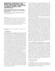
A comparison between a 20 cm airline measured by this<br />
new technique and a commercial 2-port NWA calibrated with<br />
a TRL algorithm is shown in Fig. 3. The slightly different plots<br />
for Sll could be ascribed to the small differences between the<br />
reference impedances of the TFU line and the sliding load.<br />
Fig. 4 shows the transmission S-parameters of a 30 dB<br />
standard attenuator measured between ports 1 and 3.<br />
VI. CONCLUSION<br />
A <strong>general</strong> <strong>formulation</strong> of the MNWA <strong>calibration</strong> prob-<br />
lem was presented, which provides a unified mathematical<br />
approach and defines some <strong>general</strong> criteria for <strong>calibration</strong><br />
consistency. One application of the theory leads to definition of<br />
the minimum number of required standards and demonstrates<br />
the possibility of a n-port test-set <strong>calibration</strong> by means of<br />
only one two-port standard and one sliding-load. The accuracy<br />
reached by this <strong>calibration</strong> is verified by experimental results<br />
obtained on a 3-port test-set.<br />
APPENDIX A<br />
The number of independent equations 1 given by a single<br />
two-port standard in all possible connections at a %port<br />
MNWA is derived as follows.<br />
Without loss of <strong>general</strong>ity and for mathematical simplicity,<br />
a thru is used as two-port standard. Each thru connection<br />
(1 - 2,l- 3,2 - 3) provides an equation like (24). In particular<br />
By solving (43) and (44) for e2 and e3 and by substituting<br />
into (45) we have
2460 IEEE TRANSACTIONS ON MICROWAVE THEORY AND TECHNIQUES. VOL. 42, NO. 12, DECEMBER 1994<br />
0<br />
-0.02<br />
-0.04<br />
s -0.06<br />
-0.08<br />
-0.1<br />
E -0.12<br />
-0.14<br />
- 3 prl n")<br />
1 2 3 4 5 6 7 8 9 1 0 1 1 1 2<br />
Frequency (GHz)<br />
(a)<br />
1% 1 1 1<br />
-0.2<br />
1 2 3 4 5 6 7 8 9 1 O l l 1 2<br />
Frequency (GaZ)<br />
(C)<br />
-30<br />
-35<br />
-40<br />
m<br />
3 -45<br />
f -50<br />
N -55<br />
53 -60<br />
-65<br />
-70<br />
1 2 3 4 5 6 7 8 9 1011 12<br />
Frequency (GHz)<br />
(b)<br />
0<br />
-0.02<br />
-0.04<br />
$ -0.06 - -0.0s<br />
g -0.1<br />
-0.12<br />
2 -0.14<br />
-0.16<br />
-<br />
-0*18 -0.2 : 1 2 3 4 5 6 7 8 9 1 0 1 1 1 2<br />
682<br />
a<br />
681<br />
- m<br />
u<br />
% 680<br />
e<br />
L1 679<br />
Frequency (CHz)<br />
(d)<br />
I<br />
aa<br />
678<br />
1 2 3 4 5 6 7 8 9 1 0 1 1 1 2<br />
1 2 3 4 5 6 7 8 9 1 0 1 1 I 2<br />
Frequency (GHz)<br />
Frequency (GHz)<br />
(e)<br />
(0<br />
Fig. 3. (a), (b) Coaxial airline S-parameters (20.35 cm nominal length) (c), (d) Coaxial airline transmission S-parameters (20.35 cm nominal length)<br />
(e), (f) Coaxial airline group delay (20.35 cm nominal length).<br />
Equation (46) is a linear system of four equations in three<br />
unknowns (el elements) of the form<br />
where<br />
Z<br />
(47)<br />
If the rank of the coefficient matrix Z was 3, then the overall<br />
number of independent equations I, will be (3 + 8) because<br />
4 independent equations are given from each matrix equation<br />
(43) and (44). But the solution of (47) is<br />
This is an inconsistent solution since two error coefficients are<br />
equal and the source match of port 1 (i.e., e:') is unitary, which<br />
is physically impossible. Thus the independent equations given<br />
by all connections must be less than 11. If we remove<br />
two equations from (47) and we add an equation from a<br />
measurement of a load I? at port 1, like (33), the linear<br />
system so defined has a consistent solution. Thus the number<br />
of independent equations obtained from the three possible<br />
connections plus one more load measurement equation is 11.<br />
Hence<br />
I = 10. (50)
FERRERO et al.: MULTIPODT VECTOR NETWORK ANALYZER CALIBRATION: A GENERAL FORMULATION<br />
- Reference Ihia<br />
1 2 3 4 5 6 7 8 9 1 0 1 1 1 2<br />
Frequency (GHz)<br />
(a)<br />
1 2 3 4 5 6 7 8 9 1 0 1 1 1 2<br />
Frequency (GHz)<br />
(b)<br />
Fig 4 30 dB Coaxial attenuator tranm”ion S-parameters<br />
ACKNOWLEDGMENT<br />
The authors are indebted with K. Kerwin of HP Microwave<br />
Technology Division for helpful) discussions and interesting<br />
suggestions.<br />
REFERENCES<br />
[ 1 j A. Ferrero, U. Pisani, and K. J. Kerwin, “A new implementation of a<br />
multiport automatic <strong>network</strong> <strong>analyzer</strong>,” IEEE Trans. Microwave Theory<br />
Tech., vol. 40, pp. 2078-2085, Nov. 1992.<br />
[2] A. Ferrero and U. Pisani, ‘‘Three port <strong>network</strong> <strong>analyzer</strong>: an original<br />
implementation with a simplified <strong>calibration</strong> procedure,” 1992 Asia-Pac.<br />
Mirmwave Cont, Adelaide, Australia, Aug. 11-13, 1992, pp. 915-918.<br />
[3] R. A. Speciale, “A Generalization of the TSD <strong>network</strong>-<strong>analyzer</strong> <strong>calibration</strong><br />
procedure, covering 12-port scattering-parameter measurements,<br />
affected by leakage errors,” lEEE Trans. Microwave Theory Tech., vol.<br />
MTT-25, pp. 1100-1 115, DK. 1977.<br />
[4] __, “<strong>Multiport</strong> <strong>network</strong> <strong>analyzer</strong>s: Meeting the design need,” MSN,<br />
June 1980, pp. 67-89.<br />
[5] J. C. Tippet and R. A. Speciale, “A rigorous technique for measuring the<br />
scattering matrix of a multiport device with a 2-port <strong>network</strong> <strong>analyzer</strong>,”<br />
2461<br />
IEEE Trans. Microwave Theogi Tech., vol. MTT-30, pp. 661-665, May<br />
1982.<br />
161 A. Ferrero, F. Sanpietro, and U. Pisani, “Accurate coaxial standard<br />
verification by multiport <strong>vector</strong> <strong>network</strong> <strong>analyzer</strong>.” I994 MTT-S Dig.,<br />
San Diego, CA, pp. 1365-1368, 1994.<br />
[7] K. I. Silvonen, “A <strong>general</strong> approach to <strong>network</strong> <strong>analyzer</strong> <strong>calibration</strong>,”<br />
IEEE Trans. Microwave Theory Tech., vol. 40, pp. 754-759, Apr. 1992.<br />
[8] HP 8510B Reference Manual, Santa Rosa CA, 1985.<br />
191 G. H. Golub and C. F. van Loan, Matrix Comptrrations. Baltimore,<br />
MD: Johns Hopkins University Press, 1983.<br />
[lo] G. F. Engen and C. A. Hoer, “Thru-reflect-line: An Improved technique<br />
for calibrating the dual six-port automatic <strong>network</strong> <strong>analyzer</strong>,” IEEE<br />
Trans. Microwave 7’heory Tech., Vol. MTT-27, pp. 987-993, Dec. 1979.<br />
Andrea Ferrero (S’86-M’88) was bom in Novara,<br />
Italy, in 1962. He received the electronic engi-<br />
neering degree in 1987 and the Ph.D. degree in<br />
electronics in 1992, both from the Politecnico di<br />
Torino.<br />
In 1988, he joined the Aeritalia company as<br />
a microwave consultant. In 1991, he joined the<br />
Microwave Technology Division, Hewlett-Packard,<br />
Santa Rosa, as a summer student. Currently, he is a<br />
Researcher at the Politecnico di Torino, where his<br />
main research activities are in the area of microwave<br />
measurement techniques, <strong>calibration</strong> and modeling.<br />
Ferdinand0 Sanpietro was bom in Torino, Italy, in<br />
1961. He received the electronic engineering degree<br />
in 1989 from the Politecnico di Torino. Currently,<br />
he is pursuing the Ph.D. degree in electronic engi-<br />
neering at the same university.<br />
In 1992, he joined the Microwave System Divi-<br />
sion, Hewlett Packard in Santa Rosa. His research<br />
interests include microwave device modeling, mea-<br />
surement techniques and <strong>calibration</strong>.<br />
Umberto Pisani was bom in Sora, Italy, in 1943.<br />
He received the electronic degree from Politecnico<br />
di Torino in 1967.<br />
In 1982. he became Associate Professor, and in<br />
1989 Full Professor in Electronics. He has con-<br />
ducted research in the area of active and passive<br />
device characterization and modeling, mainly of<br />
microwaves. He is presently interested in the MMlC<br />
device on-wafer characterization and measurements.