Optical Torque Sensors for Implementation of Local ... - IEEE Xplore
Optical Torque Sensors for Implementation of Local ... - IEEE Xplore
Optical Torque Sensors for Implementation of Local ... - IEEE Xplore

Create successful ePaper yourself
Turn your PDF publications into a flip-book with our unique Google optimized e-Paper software.
Proceedings <strong>of</strong> the 2006 <strong>IEEE</strong> International Conference on Robotics and Automation<br />
Orlando, Florida - May 2006<br />
<strong>Optical</strong> <strong>Torque</strong> <strong>Sensors</strong> <strong>for</strong> <strong>Implementation</strong> <strong>of</strong> <strong>Local</strong><br />
Impedance Control <strong>of</strong> the Arm <strong>of</strong> Humanoid Robot<br />
Dzmitry Tsetserukou 1 , Riichiro Tadakuma 2 , Hiroyuki Kajimoto 1 and Susumu Tachi 2<br />
Graduate School <strong>of</strong> In<strong>for</strong>mation Science and Technology<br />
The University <strong>of</strong> Tokyo<br />
7-3-1 Hongo, Bunkyo-ku, Tokyo 113-8656, Japan<br />
1 2<br />
{dima_teterukov, hiroyuki_kajimoto}@ipc.i.u-tokyo.ac.jp, {tadakuma, tachi}@star.t.u-tokyo.ac.jp<br />
Abstract - This paper describes the recent development <strong>of</strong><br />
new optical torque sensor in order to replace expensive strain<br />
gauge sensor attached at the tip <strong>of</strong> the anthropomorphic robot<br />
arm and realize local impedance control in each joint.<br />
Index Terms - <strong>Optical</strong> torque sensor, Impedance control.<br />
I. INTRODUCTION<br />
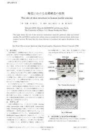
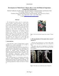
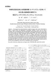
The teleoperated slave robot has been developed to realize<br />
dexterous tasks such as interaction with human in remote<br />
environment or manipulation with objects in hazardous<br />
conditions [1]. The slave robot includes anthropomorphic<br />
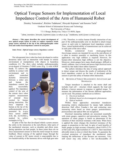
seven-degree <strong>of</strong> freedom (7-DOF) arms (Fig. 1) with 8-DOF<br />
hands. To achieve the<br />
stability in contact with<br />
environment and to<br />
realize controlled<br />
dynamic interaction<br />
between a robot arm<br />
and human the<br />
impedance control has<br />
been successfully<br />
applied. The impedance<br />
control <strong>of</strong> the arm <strong>of</strong><br />
the remote slave robot<br />
requires measurement<br />
<strong>of</strong> external <strong>for</strong>ce<br />
exerted by human<br />
during interaction. The<br />
<strong>for</strong>ce imparted by<br />
human at the tip <strong>of</strong> the<br />
anthropomorphic arm is<br />
measured by 6-axis<br />
<strong>for</strong>ce sensor (MINI<br />
4/20, BL AUTOTEC),<br />
marked by yellow<br />
rectangles in Fig. 1.<br />
Fig. 1 Teleoperated slave robot.<br />
In spite <strong>of</strong> the fact that developed robotic system ensures<br />
the safety in the interaction at the end-effector, other parts <strong>of</strong><br />
the mechanical structure, such as shoulder and elbow joint,<br />
during operation can hurt people. In these joints there are no<br />
<strong>for</strong>ce measurement sensors to limit the motor torque by means<br />
feedback. Direct sensing <strong>of</strong> the applied torque through the<br />
value <strong>of</strong> current in DC motor circuit is unacceptable due to<br />
low backdrivability <strong>of</strong> the harmonic drives with high gear ratio<br />
0-7803-9505-0/06/$20.00 ©2006 <strong>IEEE</strong> 1674<br />
(=50). There<strong>for</strong>e, to realize human friendly interaction <strong>of</strong> any<br />
part <strong>of</strong> the anthropomorphic arm we decided to attach torque<br />
sensor at each joint to implement local impedance control.<br />
Thus, virtual backdrivability <strong>of</strong> transmissions can be achieved<br />
in each joint <strong>of</strong> the slave robot.<br />
Besides, commercial 6-axis strain-gauge-based<br />
<strong>for</strong>ce/torque sensors are intended <strong>for</strong> use at the end-effector <strong>of</strong><br />
a robot to monitor assembly or machining <strong>for</strong>ces. In this<br />
application very high stiffness is required. However, <strong>for</strong><br />
human-robot interaction high stiffness is not the objective.<br />
Moreover, strain gauges have many disadvantages: difficult to<br />
install, calibrate, easy to break and posses high electrical noise<br />
sensitivity that makes them rather expensive.<br />
The authors introduce the idea <strong>of</strong> using optical approach<br />
to detect torque and discuss the results <strong>of</strong> realization <strong>of</strong> the<br />
local impedance control on the base <strong>of</strong> developed optical<br />
sensors to provide safety <strong>of</strong> human-robot interaction.<br />
II. METHODS <strong>of</strong> TORQUE MEASUREMENT. ADVANTAGES and<br />
DRAWBACKS<br />
<strong>Torque</strong> transducer is attached to the motor shaft and<br />
includes load cell – structure which supports the load and<br />
deflects a known amount in response to applied torque. To<br />
measure the de<strong>for</strong>mation <strong>of</strong> the flexure different approaches<br />
can be used. The primary methods are as follows:<br />
1) Electrical methods.<br />
2) Methods based on electromagnetic phenomena.<br />
3) <strong>Optical</strong> methods.<br />
Within these approaches noncontact transducers<br />
measuring relative displacement by means light radiation<br />
detection, Hall effect, Faraday`s law and contacting ones<br />
measuring strain based on strain gauges, potentiometers,<br />
piezoceramics and optical fibre are recognized.<br />
Electrical measuring methods are associated essentially<br />
with strain gauges, capacitive and piezoelectric sensing. The<br />
operation <strong>of</strong> strain gauges is based on phenomena <strong>of</strong> the<br />
variation <strong>of</strong> their electrical resistance with strain. When <strong>for</strong>ce<br />
is applied the strain changes the electrical resistance <strong>of</strong> the<br />
gauges in proportion to the load. In spite <strong>of</strong> such benefits <strong>of</strong><br />
strain gauges as high accuracy (linearity), about 0.03%-2.5%<br />
<strong>of</strong> full scale (FS), high resolution <strong>of</strong> 1-3mV/V, their maximum<br />
allowable strain is close at which they break. To guarantee the<br />
overload protection <strong>of</strong> transducer the mechanical stops<br />
limiting the deflections <strong>of</strong> the flexures are necessary. Very<br />
stiff sensor may only deflect a few ten-thousandths <strong>of</strong>
millimetre. Manufacturing the limit stops with such small<br />
clearances is very difficult. Besides, strain-gauge-based<br />
torque/<strong>for</strong>ce sensors are greatly subjected by radial and other<br />
<strong>for</strong>ce components. Semiconductor as well as foil gages require<br />
elaborate process <strong>for</strong> attachment which must be done by a<br />
specialist. Another shortcoming <strong>of</strong> these sensors is their<br />
sensitivity to electrical noise and temperature [2].<br />
Many torque transducers are based on measuring the<br />
relative angle between the two ends <strong>of</strong> the torsion bar. This<br />
principle was realized in differential capacitive sensor <strong>for</strong><br />
measuring the relative angle [3]. Developed transducer is<br />
noncontact, robust and compact. Two rotatable electrodes are<br />
placed between two sensor plates. The relative angle between<br />
the two rotors and the absolute position <strong>of</strong> the rotor blades are<br />
calculated from measurement <strong>of</strong> capacitive coupling between<br />
different transmitting stator segment and a single receiving<br />
electrode. Its drawback is high sensitivity to a radial<br />
displacement and high cost. The relationship between value <strong>of</strong><br />
capacitor capacity and permittivity <strong>of</strong> the dielectric material<br />
between the capacitor plates also was used in patent [4].<br />
In electromagnetic sensors the Faraday`s law (inductive<br />
sensors), magnetostriction and magnetoelastic effect are<br />
employed. As example <strong>of</strong> electromagnetic sensors – Linear<br />
Variable Differential Trans<strong>for</strong>mers (LVDT) have high degree<br />
<strong>of</strong> robustness, remarkable resolution <strong>of</strong> about 0.1m, good<br />
accuracy (0.01-0.3%), allow easier installation and calibration.<br />
Inductive sensors suffer a reduction in signal at very low<br />
frequencies and affected by electromagnetic noise.<br />
Light source, photosensor and solid object modifying<br />
amount <strong>of</strong> light incident on optical detector are necessary to<br />
measure displacement between unmovable and flexible part <strong>of</strong><br />
the optical sensor. The photosensors have such drawbacks as<br />
nonlinearity and temperature sensitivity, however, they are<br />
considerably more reliable, cheap and allow simplifying the<br />
construction <strong>of</strong> the design. A displacement can be detected by<br />
interrupting light between source and detector, changing the<br />
intensity <strong>of</strong> reflected light or relative movement <strong>of</strong> source and<br />
detector. S. Hirose and K. Yoneda have made significant<br />
contribution to research <strong>of</strong> the optical <strong>for</strong>ce and moment<br />
sensors [5, 6]. The authors proposed to use a split type<br />
photosensor to detect the displacement <strong>of</strong> the light source<br />
(LED) caused by applied <strong>for</strong>ce in two directions. In<br />
cooperation with Minebea Co. OPFT series <strong>of</strong> 6-axes optical<br />
torque sensors was manufactured. In comparison with<br />
conventional strain-gauge-based transducers they are more<br />
compact, light in weight and low in cost. However, these<br />
sensors suffer from complicated calibration procedure due to<br />
nonlinear output, require application <strong>of</strong> DSP <strong>for</strong> real-time<br />
computation <strong>of</strong> measured <strong>for</strong>ce and have average accuracy <strong>of</strong><br />
5% FS. The idea <strong>of</strong> the patent [7] is calculating torque by<br />
measuring angle <strong>of</strong> twist <strong>of</strong> the torsion shaft through detection<br />
<strong>of</strong> difference in the rotation position <strong>of</strong> discs attached at the<br />
opposite sides <strong>of</strong> the torsion shaft using optical encoder.<br />
Encoder type <strong>of</strong> torque sensor suffers from large overall<br />
dimension and complicated procedure <strong>of</strong> apertured discs<br />
mounting. To overcome this the author [8] invented torque<br />
sensor including a source <strong>of</strong> optical radiation, a two<br />
1675<br />
dimensional array <strong>of</strong> radiation detector and two modulating<br />
apertured discs placed between source and detector. As torque<br />
applied to the shaft the relative position between discs alters<br />
overlapping slots and hence the size <strong>of</strong> the apertures which<br />
control the pattern <strong>of</strong> light incident upon the optical detector.<br />
III. DEVELOPMENT OF THE OPTICAL TORQUE SENSOR<br />
Above-mentioned sensors have not been adapted to<br />
application in robot <strong>for</strong> torque detection. The approach to<br />
design high-per<strong>for</strong>mance torque sensor <strong>for</strong> anthropomorphic<br />
robot arm should follow the guidelines illustrated below.<br />
1. Addition <strong>of</strong> the torque sensor to a robot joint should<br />
not require redesign <strong>of</strong> the joint and causes a minimal<br />
modification in kinematics and dynamics. There<strong>for</strong>e, sensor<br />
with small width and lightweight is desirable.<br />
2. Noise created by current passing through the DC motor<br />
attached in each joint <strong>of</strong> the robot arm should not effect<br />
considerably on sensing element. Hence, usage <strong>of</strong><br />
electromagnetic sensors should be avoided in this application.<br />
3. The angle <strong>of</strong> twist <strong>of</strong> the movable part <strong>of</strong> transducer at<br />
the maximum expected external torque should allow<br />
exploiting as wide range <strong>of</strong> detector sensitivity as possible to<br />
achieve high signal-to-noise ratio.<br />
4. Torsional stiffness <strong>of</strong> the sensor should not<br />
considerably reduce the natural frequency <strong>of</strong> the robot arm.<br />
This introduces the trade-<strong>of</strong>f <strong>of</strong> stiffness maximization while<br />
maintaining high sensitivity.<br />
5. The other difficulty in design <strong>of</strong> the torque sensor is<br />
hysteresis elimination. Most metals used as flexures have very<br />
little hysteresis. However, bolted, press fit and welded joints<br />
near the flexure introduce hysteresis. There<strong>for</strong>e, the optimal<br />
design requires realization <strong>of</strong> the mechanical structure from a<br />
single piece <strong>of</strong> metal.<br />
6. Influence from any <strong>of</strong> the non-torsional components <strong>of</strong><br />
the load should be canceled. Behavior <strong>of</strong> the sensing element<br />
output and mechanical structure should be as close to linear as<br />
possible.<br />
7. Simple to manufacture, low in cost and robust.<br />
We decided to use ultra-small size photointerrupters type<br />
RPI-131 and RPI-121 as sensitive element to measure relative<br />
motion <strong>of</strong> sensor’s component. The relationship between the<br />
output signal and position <strong>of</strong> the shield plate <strong>for</strong> RPI-121 is<br />
shown in Fig. 2 [9].<br />
RELATIVE COLLECTOR CURRENT: Ic (%)<br />
125<br />
100<br />
75<br />
50<br />
25<br />
0<br />
0 0.5 1.0 1.5 2.0<br />
DISTANCE: d (mm)<br />
d<br />
2.5<br />
RELATIVE COLLECTOR CURRENT: Ic (%)<br />
125<br />
100<br />
75<br />
50<br />
25<br />
0<br />
0 0.5 1.0 1.5 2.0<br />
Fig. 2 Relative output vs. distance.<br />
DISTANCE: d (mm)<br />
d<br />
2.5
The linear section <strong>of</strong> the diagram corresponding<br />
approximately 0.2 mm can be used <strong>for</strong> detection <strong>of</strong> the relative<br />
displacement <strong>of</strong> the object. The dimensions <strong>of</strong><br />
photointerrupter (RPI-121 3.6 2.6 3.3 mm) and weight <strong>of</strong><br />
0.05 g allow realization <strong>of</strong> compact sensor design.<br />
Two structures <strong>of</strong> elastic element were realized: the in-line<br />
structure – when the input and output section <strong>of</strong> the detector<br />
are displaced in axial direction by the torsion component. And<br />
the “in plane” one – when input and output <strong>of</strong> the sensor are<br />
disposed in one plane and linked by the bending radial<br />
flexures. The layout <strong>of</strong> the in-line structure on the basis <strong>of</strong><br />
spring with cross-shaped cross section is presented in Fig. 3.<br />
This type <strong>of</strong> spring allows<br />
3<br />
large deflections without<br />
1<br />
4<br />
T<br />
1<br />
3<br />
Fig. 3 Construction <strong>of</strong> the<br />
optical torque sensor.<br />
input part 1, output part 2,<br />
fixedly mounted<br />
photointerrupters 3, shield 4<br />
and spring 5. When torque T<br />
is applied to the input shaft<br />
the spring will be deflected.<br />
This causes rotation motion <strong>of</strong><br />
the shield 4. The shield<br />
displacement is detected by<br />
the degree <strong>of</strong> interruption <strong>of</strong><br />
infrared light falls on the<br />
phototransistor. Thus,<br />
magnitude <strong>of</strong> the output signal<br />
<strong>of</strong> the photointerrupter will<br />
correspond to the applied torque. The relationship between the<br />
sensed torque TS and the angle <strong>of</strong> twist is the following:<br />
S S S<br />
<br />
T k k , (1)<br />
1 2<br />
where kS – torsional stiffness <strong>of</strong> the cross-shaped spring.<br />
The cross-shaped spring behavior is similar to the<br />
equivalent flat plate behavior with some linear factor<br />
differences [10]. The torsional stiffness is defined as:<br />
3<br />
k 0.98 b h t G 3l.<br />
(2)<br />
S<br />
Here l, b, h, t – working length, width, height and<br />
thickness <strong>of</strong> the cross-shaped spring correspondingly, G –<br />
shear modulus. As far as angle <strong>of</strong> twist is very small it can be<br />
calculated from the displacement <strong>of</strong> the shield in tangential<br />
direction x, then (1) becomes:<br />
TS kS x R . (3)<br />
S<br />
Where RS – distance from the sensor center to the middle<br />
<strong>of</strong> the shield plate in radial direction. The cross-shaped spring<br />
made from one piece <strong>of</strong> brass (G=3.710 10 N/m 2 , l = 12 mm, b<br />
= 10 mm, h = 10 mm, t = 1.5 mm is shown in Fig. 4.<br />
The sensor was designed to withstand torque <strong>of</strong> 1.75 Nm.<br />
The results <strong>of</strong> spring analysis using Finite Element Method<br />
(FEM) show tangential<br />
displacement in mm (Fig.<br />
5a) and von Mises stress<br />
in MPa (Fig. 5b) under<br />
torque <strong>of</strong> 1.75 Nm. The a)<br />
maximum value <strong>of</strong> von<br />
Mises stress equals<br />
vonMises = 2.39210 8 N/m 2<br />
< yield = 2.410 8 N/m 2 .<br />
Angle <strong>of</strong> twist can be<br />
calculated from the value<br />
<strong>of</strong> tangential displacement<br />
yielding. Detector consists <strong>of</strong><br />
2 and <strong>for</strong> given load it Fig. 5 Result <strong>of</strong> analysis using FEM.<br />
2<br />
5<br />
Fig. 4 Cross-shaped spring.<br />
1676<br />
b)<br />
equals 0.928. Since the<br />
maximum stress appears in the area <strong>of</strong> core <strong>of</strong> the sensor the<br />
improvement <strong>of</strong> the design can be achieved by realization <strong>of</strong><br />
hollow structure with 6 or 8 leaves <strong>of</strong> spring. The structure <strong>of</strong><br />
the test rig <strong>for</strong> calibration <strong>of</strong> the optical sensor is given on<br />
three-dimensional model (Fig. 6).<br />
Photointerrupter<br />
Fixed shaft<br />
Coupling<br />
Spring<br />
Shield<br />
Rotatable shaft<br />
Fig. 6 Structure <strong>of</strong> the test rig.<br />
Arm<br />
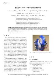
Manufactured prototype <strong>of</strong> the test rig with electrical<br />
circuit is shown in Fig. 7.<br />
Fig. 7 Test rig.<br />
Force applied to the arm, secured by screw to the rotatable<br />
shaft, creates the torque. Calibration was realized by means<br />
incrementation <strong>of</strong> angle <strong>of</strong> twist with small step and measuring<br />
output signal from the photointerrupter. Obtained relationship<br />
on linear section <strong>of</strong> trans<strong>for</strong>mation <strong>of</strong> displacement to voltage<br />
is shown in Fig. 8. This diagram can be rebuilt in term <strong>of</strong><br />
applied torque, since torsional stiffness is known.
Fig. 8 Relationship <strong>of</strong> output voltage vs. angle <strong>of</strong> twist.<br />
The “in plane” structure <strong>of</strong> the optical torque sensor<br />
includes the radial flexures subjected by loading bending<br />
<strong>for</strong>ces while loading state. The layout <strong>of</strong><br />
three-beam-hub-spoke structure is presented in Fig. 9.<br />
3 2<br />
b<br />
l<br />
r<br />
t<br />
1<br />
R S<br />
<br />
Fig. 9 Hub-spoke structure layout.<br />
In Fig. 9 the following designations are given: 1 – beam, 2<br />
– photointerrupter, 3 – shield. The rigidity <strong>of</strong> the hub can be<br />
increased by introducing additional evenly distributed spokes<br />
[11]. The torsional stiffness <strong>of</strong> hub-spoke structure is derived<br />
from:<br />
2<br />
1 3r 3r<br />
<br />
2 3 <br />
kS4NEI , (4)<br />
l l l <br />
where N – number <strong>of</strong> spokes, l – the spoke length, E –<br />
modulus <strong>of</strong> elasticity, r – inner radius <strong>of</strong> the sensor [12].<br />
Moment <strong>of</strong> inertia <strong>of</strong> the spoke cross section I can be<br />
calculated as:<br />
3<br />
bt<br />
I , (5)<br />
12<br />
here b – beam width, t – beam thickness. The sensor was<br />
designed to support <strong>of</strong> 0.8 Nm torque which arises in the<br />
elbow joint <strong>of</strong> the robot arm. The results <strong>of</strong> analysis using<br />
FEM show von Mises stress in MPa (Fig. 10a) and the<br />
tangential displacement in mm (Fig. 10b) under torque <strong>of</strong> 0.8<br />
Nm. The maximum value <strong>of</strong> von Mises stress equals vonMises =<br />
14.5710 7 N/m 2 < yield = 15.010 7 N/m 2 .<br />
D<br />
<br />
1677<br />
a) b)<br />
Fig. 10 Result <strong>of</strong> analysis <strong>of</strong> hub-spoke spring using FEM.<br />
The test rig <strong>for</strong> calibration <strong>of</strong> the optical sensor has been<br />
created (Fig.11). The procedure <strong>of</strong> calibration is the same as<br />
previous sensor.<br />
Fig. 11 Test rig.<br />
Obtained relationship between angle <strong>of</strong> twist and output<br />
voltage is shown in Fig. 12.<br />
Fig. 12 Calibration result.<br />
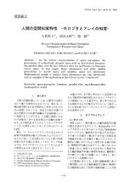
The sensor was manufactured from one piece <strong>of</strong> brass by<br />
using wire electrical discharge machining (EDM) cutting to<br />
eliminate hysteresis and guarantee high strength (Fig.13).<br />
Fig. 13 <strong>Optical</strong> torque sensor with hub-spoke-shaped flexure.
In this sensor the photointerrupter type RPI-121 was used.<br />
The thickness <strong>of</strong> the sensor body is only 6.5 mm. The<br />
adjustment <strong>of</strong> the shield position is realized by rotation <strong>of</strong><br />
oppositely located screws. The pitch <strong>of</strong> the screws is enough<br />
<strong>for</strong> smooth movement <strong>of</strong> the slider with shield plate.<br />
In order to extend exploiting range <strong>of</strong> photodetector<br />
sensitivity keeping same strength the ring-shaped spring was<br />
designed. Components and assembly <strong>of</strong> the developed optical<br />
torque sensor are presented in Fig. 14. The flexible ring is<br />
connected with inner and outer part <strong>of</strong> the sensor though<br />
beams. The inner and outer beams are displaced with angle <strong>of</strong><br />
90 that enables large compliance <strong>of</strong> the ring-shaped flexure.<br />
The results <strong>of</strong> analysis using FEM under torque <strong>of</strong> 0.8 Nm<br />
are given in Fig. 14 (a – von Mises stress in MPa; b –<br />
tangential displacement in mm). The maximum value <strong>of</strong> stress<br />
equals vonMises = 8.6210 7 N/m 2 < yield = 8.9610 7 N/m 2 .<br />
a)<br />
Fig. 14 <strong>Optical</strong> torque sensor with ring-shaped flexure.<br />
Fig. 15 Result <strong>of</strong> analysis <strong>of</strong> the ring-shaped spring using FEM.<br />
Obtained relationship between angle <strong>of</strong> twist and the<br />
output voltage <strong>of</strong> photointerrupter is shown in Fig. 16.<br />
b)<br />
Fig. 16 Calibration result.<br />
1678<br />
The thickness <strong>of</strong> the sensor is 10 mm. Displacement <strong>of</strong> the<br />
shield is measured by photointerrupter type RPI-131. The<br />
shortcomings <strong>of</strong> this design are complicated procedure <strong>of</strong><br />
adjusting the position <strong>of</strong> the shield relatively photosensor and<br />
deficiency <strong>of</strong> the housing to prevent from damage <strong>of</strong> the<br />
optical transducer. Technical specification <strong>of</strong> the realized<br />
optical torque sensors is listed in Table I.<br />
TABLE I<br />
TECHNICAL SPECIFICATION<br />
Type <strong>of</strong> sensor Cross-shaped Hub-spoke-shaped Ring-shaped<br />
spring<br />
spring<br />
spring<br />
Spring material Brass C2801 Brass C2801<br />
Aluminium<br />
A5052<br />
Load<br />
Nm<br />
capacity,<br />
1.75 0.8 0.8<br />
Torsional<br />
stiffness,<br />
Nm/rad<br />
90.02 219.8 115.9<br />
Factor <strong>of</strong> safety 1.0 1.0 1.0<br />
Photointerrupter<br />
type<br />
RPI-131 RPI-121 RPI-131<br />
Outer diameter,<br />
mm<br />
30 42 42<br />
Thickness, mm 30 6.5 10<br />
Sensor mass, g 36 34.7 28.7<br />
Cross-shaped spring provides transmission <strong>of</strong> large torque<br />
and small outer diameter <strong>of</strong> the sensor. However, this spring<br />
introduces considerable angle error caused significant<br />
compliance. Spoke-hub topology allows realization <strong>of</strong><br />
compact in axial direction sensor. However, big torsional<br />
stiffness diminishes resolution <strong>of</strong> photointerrupter. Probably,<br />
the optimal solution is the ring-shaped flexure providing wide<br />
range <strong>of</strong> torsional stiffness with high mechanical strength. The<br />
main shortcoming <strong>of</strong> this topology is high sensitivity to the<br />
bending moment. Nevertheless, this obstacle can be overcome<br />
trough realization <strong>of</strong> simple supported loading shaft <strong>of</strong> the<br />
robot joint. In the most loaded joints, e.g. shoulder joint, such<br />
material as hardened stainless steel can be used <strong>for</strong> elastic<br />
element to keep the sensor dimension.<br />
IV. LOCAL IMPEDANCE CONTROL<br />
The aim <strong>of</strong> the impedance control is to establish the<br />
dynamic relationship between position error and <strong>for</strong>ce error in<br />
interaction similar to Newton`s second low <strong>of</strong> motion. The<br />
graphical presentation <strong>of</strong> concept <strong>of</strong> the local impedance<br />
control is given in Fig. 17.<br />
Kdi<br />
D<br />
di<br />
K<br />
EXTi<br />
Fig. 17 Concept <strong>of</strong> the local impedance control.<br />
J<br />
di Dd(i+1)<br />
d(i+1)<br />
F EXT<br />
J<br />
<br />
d(i+1)<br />
EXT (i+1)
In joint space system desired dynamics <strong>of</strong> robot joint i is:<br />
J D K ; <br />
, (6)<br />
EXTi di i di i di i i ci di<br />
here EXTi – torque applied to joint i caused by external <strong>for</strong>ce<br />
FEXT, Jdi – desired inertia, Ddi – desired damping, Kdi – desired<br />
stiffness, ci – output joint angle <strong>of</strong> the impedance model, di –<br />
desired joint angle. The state-space presentation <strong>of</strong> the<br />
equation <strong>of</strong> local impedance control can be written:<br />
0 1 i 0<br />
i <br />
= EXTi ( t)<br />
v Kd Jd Dd J<br />
<br />
d v<br />
<br />
i 1 J<br />
<br />
. (7)<br />
<br />
i d<br />
Where state variable is defined as i i<br />
v .<br />
After integration <strong>of</strong> (7) the discrete time presentation <strong>of</strong><br />
impedance equation can be expressed as:<br />
<br />
= A B T<br />
<br />
<br />
<br />
<br />
<br />
k+1 k<br />
d d EXT( k)<br />
k+1 k<br />
. (8)<br />
Where Ad and Bd – matrixes mapped by discretization. In<br />
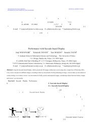
order to verify the dynamic behavior <strong>of</strong> the optical torque<br />
sensor the local impedance control <strong>of</strong> links <strong>of</strong> simple SCARA<br />
type manipulator was implemented (Fig.18, torque sensors are<br />
marked by ovals, gear ratio <strong>of</strong> speed reducers equals 2548).<br />
Fig. 18 SCARA manipulator and response plot.<br />
Block diagram <strong>of</strong> realized position based local impedance<br />
control system is presented in Fig. 19 (KP and KD –<br />
proportional and derivative feedback gains respectively).<br />
Target<br />
trajectory<br />
generator<br />
<br />
k+1<br />
<br />
d<br />
d<br />
<br />
Impedance<br />
trajectory<br />
generator<br />
d<br />
<br />
k+1 <br />
k+1<br />
c<br />
Kv<br />
s<br />
c<br />
A/D<br />
K p<br />
<br />
Fig. 19 Block diagram <strong>of</strong> the position based impedance control.<br />
The second-order low-pass filter was implemented to<br />
eliminate noise component with cut<strong>of</strong>f frequency <strong>of</strong> 80 Hz.<br />
V. CONCLUSION<br />
New optical torque sensors in order to replace the<br />
strain-gage-based 6-axis <strong>for</strong>ce/torque sensor and realize virtual<br />
backdrivability <strong>of</strong> joint transmissions have been developed.<br />
These sensors are compact, light in weight, easy to<br />
manufacture, moreover, they have good linearity, enough<br />
resolution and electromagnetic noise immunity. Position based<br />
local impedance control <strong>of</strong> SCARA type manipulator has been<br />
successfully implemented. The new anthropomorphic arm<br />
with ability build in developed torque sensors has been<br />
designed. New stage <strong>of</strong> research is realization <strong>of</strong> the local<br />
impedance control <strong>of</strong> each joint <strong>of</strong> the robot arm.<br />
REFERENCES<br />
[1] R. Tadakuma, Y. Asahara, H. Kajimoto, N. Kawakami, and S. Tachi:<br />
Development <strong>of</strong> anthropomorphic multi-D.O.F. master-slave arm <strong>for</strong><br />
mutual telexistence, <strong>IEEE</strong> Transactions on Visualization and Computer<br />
Graphics, vol. 11, no. 6, pp. 626-636, November 2005<br />
[2] J. D. Turner and M. H. Westbrook, Automotive <strong>Sensors</strong>. Bristol, U.K.:IOP,<br />
1993.<br />
[3] P. L. Fulmek, F. Wandling, W. Zdiarsky, G. Brasseur, and S. P. Cermak,<br />
“Capacitive sensor <strong>for</strong> relative angle measurement, ” <strong>IEEE</strong> Transactions<br />
on Instrumentation and Measurement, vol. 51, no. 6, pp. 1145-1149,<br />
December 2002.<br />
[4] A. M. Madni, R. K. Hansen, and J. B. Vuong, “Differential capacitive<br />
torque sensor,” U.S. Patent No. 6 772 646, 2004.<br />
[5] S. Hirose and K. Yoneda, “Robotic sensors with photodetecting<br />
technology,” Proc. <strong>of</strong> 20 th International Symposium on Industrial<br />
Robotics, pp. 271-278, 1989.<br />
[6] S. Hirose and K. Yoneda, “Development <strong>of</strong> optical 6-axial <strong>for</strong>ce sensor<br />
and its non-linear calibration,” J. <strong>of</strong> RSJ, vol. 8-25, pp. 19-28, 1990.<br />
[7] N. Okutani and K. Nakazawa, “Torsion angle detection apparatus and<br />
torque sensor,” U. S. Patent No. 5 247 839, 1993.<br />
[8] S. J. Horton, “Displacement and torque sensor,” U. S. Patent No. 6 800<br />
843 B2, 2004.<br />
[9] Photointerrupter Design Guide. Product catalog <strong>of</strong> ROHM, pp. 6-7,<br />
2005.<br />
[10] M. M. Williamson, “Robot arm control exploiting natural dynamics,”<br />
PhD thesis, Massachusetts Institute <strong>of</strong> Technology, 1999.<br />
[11] C. Nicot, “<strong>Torque</strong> sensor <strong>for</strong> a turning shaft,” U. S. Patent No. 6 694 828<br />
B1, 2004.<br />
[12] D. Vischer and O. Khatib, “Design and development <strong>of</strong><br />
high-per<strong>for</strong>mance torque controlled joints,” <strong>IEEE</strong> Transactions on<br />
Robotic and Automation, vol. 11, no. 4, pp. 537-544, August 1995.<br />
Digital lowpass filter<br />
c<br />
1679<br />
1<br />
Ki KT D/A<br />
<strong>Optical</strong> torque<br />
sensor<br />
Encoder<br />
i<br />
m<br />
Driver Link