


Create successful ePaper yourself
Turn your PDF publications into a flip-book with our unique Google optimized e-Paper software.
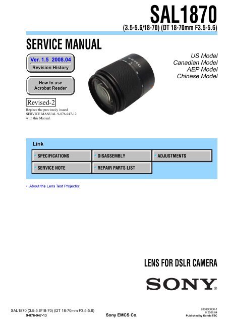
SERVICE MANUAL<br />
Ver. 1.5 2008.04<br />
Revision Revision History History<br />
How to use<br />
Acrobat Acrobat Reader Reader<br />
Revised-2<br />
Replace the previously issued<br />
SERVICE MANUAL 9-876-947-12<br />
with this Manual.<br />
Link<br />
SPECIFICATIONS<br />
SERVICE NOTE<br />
• About the <strong>Lens</strong> Test Projector<br />
<strong>SAL1870</strong> (3.5-5.6/18-70) (DT 18-70mm F3.5-5.6)<br />
9-876-947-13<br />
DISASSEMBLY ADJUSTMENTS<br />
REPAIR PARTS LIST<br />
Sony EMCS Co.<br />
<strong>SAL1870</strong><br />
(3.5-5.6/18-70) (DT 18-70mm F3.5-5.6)<br />
US Model<br />
Canadian Model<br />
AEP Model<br />
Chinese Model<br />
LENS FOR DSLR CAMERA<br />
2008D0800-1<br />
© 2008.04<br />
Published by Kohda TEC
<strong>SAL1870</strong> (3.5-5.6/18-70) (DT 18-70mm F3.5-5.6)<br />
SPECIFICATIONS<br />
• This lens is equipped with a distance encoder. The distance encoder allows more accurate measurement (ADI) by using a flash for ADI.<br />
• Depending on the lens mechanism, the focal length may change with any change of the shooting distance. The focal length assumes the lens is focused<br />
at infinity.<br />
Equivalent 35mm-format focal length * 1 (mm)<br />
27-105<br />
<strong>Lens</strong> groups elements<br />
9-11<br />
Angle of view * 1<br />
76°-23°<br />
* 1 The values for equivalent 35mm-format focal length and angle of view are based on Digital Single <strong>Lens</strong> Reflex Cameras equipped with an APS-<br />
C sized image sensor.<br />
Minimum focus * 2 (m (feet))<br />
0.38 (1.2)<br />
* 2 Minimum focus is the shortest distance from the image sensor to the subject.<br />
Maximum magnification (X)<br />
0.25<br />
Minimum f-stop<br />
f/22-36<br />
Filter diameter (mm)<br />
55<br />
Dimensions (maximum diameter × height) (mm (in.))<br />
Approx. 66 × 77 (2 5/8 × 3 1/8)<br />
Mass (g (oz.))<br />
Approx. 235 (8 5/16)<br />
Included items<br />
<strong>Lens</strong> (1), Front lens cap (1), Rear lens cap (1), <strong>Lens</strong> hood (1), Set of printed documentation<br />
Designs and specifications are subject to change without notice.<br />
— 2 —
TABLE OF CONTENTS<br />
Section Title Page<br />
1. SERVICE NOTE<br />
1-1. Chemicals ·······································································1-1<br />
1-2. Exterior Parts ··································································1-1<br />
1-3. Unleaded Solder ·····························································1-1<br />
1-4. Safty Check-out ······························································1-2<br />
1-5. Troubleshooting ·····························································1-3<br />
2. DISASSEMBLY<br />
2-1. Disassembly ···································································2-2<br />
3. REPAIR PARTS LIST<br />
3-1. Exploded Views ······························································3-1<br />
3-2. Supplied Accessories ······················································3-6<br />
4. ADJUSTMENTS<br />
4-1. Preparations ····································································4-1<br />
4-2. Aperture Diameter Check/Adjustment ···························4-4<br />
4-3. Projective Resolving Power Check ································4-9<br />
4-4. Focus-shift/Flange Back (f’F) Check/Adjustment ······· 4-12<br />
4-5. <strong>Lens</strong> ROM Check ·························································4-16<br />
4-6. Zoom Brush Position Check/Adjustment and<br />
Pattern Check ······························································· 4-17<br />
4-7. Focus Brush Position Check/Adjustment and<br />
Pattern Check ······························································· 4-20<br />
4-8. Error Code List ·····························································4-23<br />
<strong>SAL1870</strong> (3.5-5.6/18-70) (DT 18-70mm F3.5-5.6)<br />
— 3 —
1-1. Chemicals<br />
<strong>SAL1870</strong> (3.5-5.6/18-70) (DT 18-70mm F3.5-5.6)<br />
1. SERVICE NOTE<br />
Some chemicals used for servicing are highly volatile.<br />
Their evaporation caused by improper management affects your health and environment, and wastes resources.<br />
Manage the chemicals carefully as follows.<br />
• Store chemicals sealed in a specific place to prevent from exposure to high temperature or direct sunlight.<br />
• Avoid dividing chemicals into excessive numbers of small containers to reduce natural evaporation.<br />
• Keep containers sealed to avoid natural evaporation when chemicals are not in use.<br />
• Avoid using chemicals as much as possible. When using chemicals, divide only required amount to a small plate from the container and<br />
use up it.<br />
1-2. Exterior Parts<br />
Be careful to the following points for exterior parts used in this unit.<br />
• Use a piece of cleaning paper or cleaning cloth for cleaning exterior parts. Avoid using chemicals.<br />
Even if you have to use chemicals to clean heavy dirt, don’t use paint thinner, ketone, nor alcohol.<br />
• Insert the specific screws vertically to the part when installing a exterior part.<br />
Be careful not to tighten screws too much.<br />
1-3. Unleaded Solder<br />
This unit uses unleaded solder.<br />
Boards requiring use of unleaded solder are printed with the lead free mark (LF) indicating the solder contains no lead.<br />
(Caution: Some printed circuit boards may not come printed with the lead free mark due to their particular size.)<br />
: LEAD FREE MARK<br />
Be careful to the following points to solder or unsolder.<br />
• Set the soldering iron tip temperature to 350 °C approximately.<br />
If cannot control temperature, solder/unsolder at high temperature for a short time.<br />
Caution: The printed pattern (copper foil) may peel away if the heated tip is applied for too long, so be careful!<br />
Unleaded solder is more viscous (sticky, less prone to flow) than ordinary solder so use caution not to let solder bridges<br />
occur such as on IC pins, etc.<br />
• Be sure to control soldering iron tips used for unleaded solder and those for leaded solder so they are managed separately. Mixing<br />
unleaded solder and leaded solder will cause detachment phenomenon.<br />
1-1
1-4. SAFETY CHECK-OUT<br />
After correcting the original service problem, perform the following safety checks before releasing the set to the customer.<br />
1. Check the area of your repair for unsoldered or poorly-soldered connections. Check the entire board surface for solder splashes and<br />
bridges.<br />
2. Check the interboard wiring to ensure that no wires are “pinched” or contact high-wattage resistors.<br />
3. Look for unauthorized replacement parts, particularly transistors, that were installed during a previous repair. Point them out to the<br />
customer and recommend their replacement.<br />
4. Look for parts which, through functioning, show obvious signs of deterioration. Point them out to the customer and recommend their<br />
replacement.<br />
5. Check the B+ voltage to see it is at the values specified.<br />
6. Flexible Circuit Board Repairing<br />
• Keep the temperature of the soldering iron around 270 °C during repairing.<br />
• Do not touch the soldering iron on the same conductor of the circuit board (within 3 times).<br />
• Be careful not to apply force on the conductor when soldering or unsoldering.<br />
CAUTION<br />
Danger of explosion if battery is incorrectly replaced.<br />
Replace only with the same or equivalent type.<br />
SAFETY-RELATED COMPONENT WARNING!!<br />
COMPONENTS IDENTIFIED BY MARK 0 OR DOTTED LINE WITH<br />
MARK 0 ON THE SCHEMATIC DIAGRAMS AND IN THE PARTS<br />
LIST ARE CRITICAL TO SAFE OPERATION. REPLACE THESE<br />
COMPONENTS WITH SONY PARTS WHOSE PART NUMBERS<br />
APPEAR AS SHOWN IN THIS MANUAL OR IN SUPPLEMENTS<br />
PUBLISHED BY SONY.<br />
<strong>SAL1870</strong> (3.5-5.6/18-70) (DT 18-70mm F3.5-5.6)<br />
1-2<br />
ATTENTION AU COMPOSANT AYANT RAPPORT<br />
À LA SÉCURITÉ!<br />
LES COMPOSANTS IDENTIFÉS PAR UNE MARQUE 0 SUR LES<br />
DIAGRAMMES SCHÉMATIQUES ET LA LISTE DES PIÈCES SONT<br />
CRITIQUES POUR LA SÉCURITÉ DE FONCTIONNEMENT. NE<br />
REMPLACER CES COMPOSANTS QUE PAR DES PIÈSES SONY<br />
DONT LES NUMÉROS SONT DONNÉS DANS CE MANUEL OU<br />
DANS LES SUPPÉMENTS PUBLIÉS PAR SONY.
Ver 1.1 2007.02<br />
1-5. TROUBLESHOOTING<br />
1-5-1. Aperture Trouble<br />
NG<br />
Replace the lens<br />
mount block.<br />
Check operation of<br />
the preset ring.<br />
NG<br />
<strong>SAL1870</strong> (3.5-5.6/18-70) (DT 18-70mm F3.5-5.6)<br />
Function NG F No. NG<br />
Check operation<br />
of the rear lens<br />
group block.<br />
Replace the rear lens<br />
group block.<br />
Perform the aperture<br />
diameter adjustment.<br />
(See page 4-7.)<br />
1-3<br />
Perform the aperture<br />
diameter check.<br />
(See page 4-4.)<br />
OK OK<br />
OK<br />
Aperture trouble<br />
NG<br />
NG<br />
Replace the lens<br />
mount block.<br />
Perform the aperture<br />
diameter check.<br />
(See page 4-4.)<br />
END<br />
OK<br />
NG
1-5-2. Zoom Trouble<br />
NG<br />
Function NG Position NG<br />
Disassembly and check<br />
the zoom relation parts.<br />
NG<br />
Replace the defective part<br />
or apply the grease.<br />
Check the operation<br />
again.<br />
OK<br />
OK<br />
<strong>SAL1870</strong> (3.5-5.6/18-70) (DT 18-70mm F3.5-5.6)<br />
Zoom trouble<br />
Adjust the position, or<br />
replace the zoom brush.<br />
Clean the pattern of the<br />
zoom flexible.<br />
1-4<br />
NG<br />
NG<br />
Check the position<br />
and deformation<br />
at the tip of<br />
the zoom brush.<br />
OK<br />
Check pattern<br />
of the zoom flexible.<br />
OK<br />
Replace the main<br />
flexible block.<br />
Perform the<br />
zoom brush position<br />
check/adjustment.<br />
(See page 4-17.)<br />
END<br />
OK<br />
NG
1-5-3. Focus Trouble<br />
NG<br />
Replace the defective part<br />
or apply the grease.<br />
NG<br />
OK<br />
NG<br />
Replace the defective part<br />
or apply the grease.<br />
Check the operation<br />
again.<br />
OK<br />
<strong>SAL1870</strong> (3.5-5.6/18-70) (DT 18-70mm F3.5-5.6)<br />
Focus trouble<br />
Function NG Position NG<br />
Check the<br />
AF coupler and<br />
coupler gear.<br />
Check the<br />
gear barrel.<br />
OK<br />
1-5<br />
NG<br />
Adjust the position, or<br />
replace the focus brush.<br />
NG<br />
Clean the pattern of the<br />
focus flexible.<br />
Check the position<br />
and deformation<br />
at the tip of<br />
the focus brush.<br />
END<br />
OK<br />
Check pattern<br />
of the focus flexible.<br />
OK<br />
Replace the main<br />
flexible block.<br />
Perform the<br />
focus brush position<br />
check/adjustment.<br />
(See page 4-20.)<br />
OK<br />
NG
Ver 1.1 2007.02<br />
NOTE FOR REPAIR<br />
<strong>SAL1870</strong> (3.5-5.6/18-70) (DT 18-70mm F3.5-5.6)<br />
2. DISASSEMBLY<br />
• Make sure that the flat cable and flexible board are not cracked of bent at the terminal.<br />
Do not insert the cable insufficiently nor crookedly.<br />
• When remove a connector, dont’ pull at wire of connector. It is possible that a wire is snapped.<br />
• When installing a connector, dont’ press down at wire of connector.<br />
It is possible that a wire is snapped.<br />
• Do not apply excessive load to the gilded flexible board.<br />
UNIVERSAL WRENCH<br />
In case of the following notches or holes are located in the lens block, etc during disassembling/<br />
assembling the lens, Use the universal wrench.<br />
How to Use<br />
Notches Holes<br />
Universal wrench<br />
J-6082-609-A<br />
Attach the chip-A or chip-B to the universal wrench.<br />
For the notches: chip-A<br />
For the holes: chip-B<br />
Match the universal wrench to the holes or notches of the lens block, etc.<br />
Match the universal wrench<br />
to the width of holes or notches.<br />
Fixed screw<br />
Chip<br />
Chip<br />
Fixed screw<br />
Chip-A for<br />
universal wrench:<br />
J-6082-609-1<br />
Universal wrench<br />
When top of tip does not reach holes or notches because the fixed screw becomes obstructive,<br />
replace the fixed screw to below.<br />
+B 3X5 7-682-546-09<br />
2-1<br />
Chip-A<br />
Chip-B<br />
Cut and remove the part of gilt<br />
which comes off at the point.<br />
(Be careful or some<br />
pieces of gilt may be left inside)<br />
Notches<br />
Holes<br />
Chip-B for<br />
universal wrench:<br />
J-6082-609-2<br />
Chip-A<br />
Chip-B
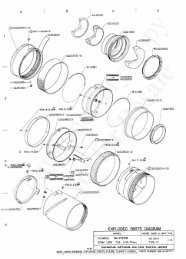
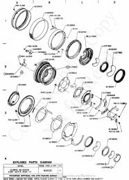
2-1. DISASSEMBLY<br />
2-1-1. LENS MOUNT BLOCK AND ZOOM RETAINER TUBE BLOCK<br />
1 Main Flexible Block<br />
FOCUS-SHIFT/<br />
FLANGE BACK<br />
ADJUSTMENT<br />
3 Back Adjustment Washer<br />
5 Zoom Retainer Tube<br />
Block<br />
(See Page 2-3.)<br />
8 Zoom Rubber Ring<br />
<strong>SAL1870</strong> (3.5-5.6/18-70) (DT 18-70mm F3.5-5.6)<br />
EXPLODED VIEW<br />
2-2<br />
2 Mount Decoration Plate<br />
and <strong>Lens</strong> Mount Block<br />
APERTURE DIAMETER<br />
ADJUSTMENT<br />
4 AF Coupler<br />
HELP01<br />
4 Coupler Adjustment<br />
Washer<br />
FOCUS-SHIFT/<br />
FLANGE BACK<br />
ADJUSTMENT<br />
6 Coupler Gear<br />
HELP02<br />
9 Zoom Guide Roller<br />
7 Brush<br />
ZOOM BRUSH POSITION<br />
ADJUSTMENT
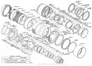
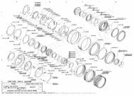
2-1-2. GEAR BARREL, ZOOM CAM BARREL AND ZOOM CONTROL TUBE BLOCK<br />
HELP06<br />
HELP05<br />
HELP04<br />
HELP03<br />
EXPLODED VIEW<br />
7 Focus Stopper<br />
9 1st Moving<br />
Barrel<br />
0 Zoom<br />
Barrel<br />
8 Front <strong>Lens</strong><br />
Barrel<br />
<strong>SAL1870</strong> (3.5-5.6/18-70) (DT 18-70mm F3.5-5.6)<br />
FOCUS-SHIFT<br />
/FLANGE BACK<br />
ADJUSTMENT<br />
HELP07<br />
2-3<br />
EXPLODED VIEW<br />
FOCUS BRUSH POSITION<br />
ADJUSTMENT<br />
4 Focus Brush<br />
HELP08<br />
HELP09<br />
HELP10<br />
3 Joint Tube<br />
Block<br />
(See Page 2-4.)<br />
6 Gear Barrel<br />
5 Zoom Cam<br />
Barrel<br />
1 Zoom Coupling<br />
Roller<br />
2 Zoom Control<br />
Tube Block<br />
HELP10
Ver 1.2 2007.05<br />
2-1-3. JOINT TUBE BLOCK<br />
1 Rear Component<br />
<strong>Lens</strong> Block<br />
Never disassemble this part.<br />
HELP11<br />
<strong>SAL1870</strong> (3.5-5.6/18-70) (DT 18-70mm F3.5-5.6)<br />
EXPLODED VIEW<br />
2-4<br />
HELP13<br />
2 Fixed Barrel<br />
HELP12<br />
3 Joint Tube Block
HELP01<br />
Grease (G-80): J-6082-625-A<br />
Grease (G-85): J-6082-626-A<br />
<strong>SAL1870</strong> (3.5-5.6/18-70) (DT 18-70mm F3.5-5.6)<br />
Note for assembling and grease applying positions are shown.<br />
Apply the grease (G-80, G-85) to the instruction part of the AF coupler.<br />
Apply the grease (G-85)<br />
HELP02<br />
Grease (G-85): J-6082-626-A<br />
Apply the grease (G-85) to the instruction part of the coupler gear.<br />
HELP03<br />
Apply the grease (G-85)<br />
HELP<br />
Attach the polyester tape (black) 10mm and friction sheet-A to the zoom barrel as illustrated.<br />
Reference line<br />
Gate portion<br />
Apply the grease (G-80)<br />
Polyester Tape (Black) 10mm<br />
(1mm x 40mm)<br />
Friction Sheet-A<br />
Tip portion of the zoom barrel Enlarged section of the zoom barrel<br />
HELP
HELP04<br />
Attach the black decoration line to the zoom barrel as illustrated.<br />
Note: Attach the black decoration line from the opposite side of zoom scale “35” for hiding the extra scraps.<br />
Black Decoration Line<br />
HELP05<br />
Grease (G-116): J-6082-628-A<br />
Anti-diffusion agent (A-20): J-6082-611-A<br />
Apply the grease (G-116) and anti-diffusion agent (A-20) to the instruction part of the zoom barrel.<br />
HELP06<br />
Grease (G-116): J-6082-628-A<br />
Anti-diffusion agent (A-20): J-6082-611-A<br />
Apply the grease (G-116) and anti-diffusion agent (A-20) to the instruction part of the 1st moving barrel.<br />
Apply the anti-diffusion agent<br />
(A-20) (All circumference)<br />
Enlarged section of the zoom barrel<br />
Apply the grease (G-116) (Groove portion)<br />
Apply the anti-diffusion agent (A-20)<br />
(Circumference of inside and outside)<br />
Apply the grease (G-116)<br />
(Helicoid: Inside circumference)<br />
Apply the grease (G-116)<br />
(Liner groove: 3 areas)<br />
<strong>SAL1870</strong> (3.5-5.6/18-70) (DT 18-70mm F3.5-5.6)<br />
Apply the grease (G-116)<br />
(Both side of cam portion: 3 areas)<br />
HELP
HELP07<br />
Anti-diffusion agent (A-20): J-6082-611-A<br />
Adhesive bond (B-10): J-6082-612-A<br />
1. Match the positions of 1st moving barrel and zoom barrel as illustrated.<br />
2. Insert the 1st moving barrel into the zoom barrel to the end with setting projection and linear groove.<br />
After inserting, check that the positions of the window of zoom barrel and the hole of 1st moving barrel are as shown in the Fig.1.<br />
1st Moving Barrel<br />
Zoom Barrel<br />
Projections<br />
Liner groove<br />
3. Turn the 1st moving barrel to the arrow direction about 10 degrees, and engage the cam part of the 1st moving barrel and projection<br />
of the zoom barrel as shown in the figure.<br />
Check that the positions of the window of zoom barrel and the hole of 1st moving barrel are as shown in the Fig.2.<br />
Projections of the<br />
zoom barrel<br />
Turn the 1st moving barrel<br />
about 10 degrees<br />
<strong>SAL1870</strong> (3.5-5.6/18-70) (DT 18-70mm F3.5-5.6)<br />
Hole<br />
Window<br />
Cam portion of the<br />
1st moving barrel<br />
Fig.1<br />
Fig.2<br />
HELP
4. Apply the anti-diffusion agent (A-20) to the instruction part of the front lens barrel.<br />
5. Match the positions of the window and the focus linear slider as shown in the figure, and attach the front lens barrel to the 1st moving<br />
barrel.<br />
6. Connect helicoidally the front lens barrel to the 1st moving barrel by turning it about 180 degrees in the direction of the arrow.<br />
1st Moving Barrel<br />
Window<br />
Focus liner slider<br />
Front <strong>Lens</strong> Barrel<br />
7. Attach the focus stopper as shown in the figure, and fix it with the two screws tentatively.<br />
8. After the focus-shift/flange back (f’F) adjustment is completed, apply the adhesive bond (B-10) as shown in the figure.<br />
Apply the adhesive bond (B-10)<br />
<strong>SAL1870</strong> (3.5-5.6/18-70) (DT 18-70mm F3.5-5.6)<br />
About 180 degrees<br />
Apply the anti-diffusion agent<br />
(A-20) (All circumference)<br />
Focus Stopper<br />
HELP
HELP08<br />
Grease (G-116): J-6082-628-A<br />
1. Apply the grease (G-116) to the instruction part of the gear barrel.<br />
Apply the grease (G-116)<br />
(Circumference area)<br />
2. Match the positions of joint tube block and gear barrrel, and insert the gear barrel into the joint tube block to the end as shown in the<br />
figure.<br />
3. Turn the gear barrel about 15 degrees from the end to the arrowed direction, and engage bayonet to the joint tube block.<br />
Joint Tube Block<br />
About 15 degrees<br />
from the end to the<br />
arrowed direction<br />
<strong>SAL1870</strong> (3.5-5.6/18-70) (DT 18-70mm F3.5-5.6)<br />
Apply the grease (G-116)<br />
(Both sides: 3 areas)<br />
Gear Barrel<br />
HELP
HELP09<br />
Grease (G-116): J-6082-628-A<br />
1. Apply the grease (G-116) to the instruction part of the zoom cam barrel.<br />
Apply the grease (G-116) (Cam part: 3 areas) Apply the grease (G-116) (All circumference)<br />
2. Match the positions of joint tube block and zoom cam barrel, and insert the zoom cam barrel into the joint tube block to the end as<br />
shown in the figure.<br />
3. Turn the zoom cam barrel about 90 degrees from the end to the arrowed direction, and engage bayonet to the joint tube block.<br />
Joint Tube Block<br />
About 90 degrees<br />
from the end to the<br />
arrowed direction<br />
Zoom Cam Barrel<br />
<strong>SAL1870</strong> (3.5-5.6/18-70) (DT 18-70mm F3.5-5.6)<br />
HELP
HELP10<br />
1. Turn the gear barrel until the two screw holes of the gear barrel are seen from the square window as shown in the figure.<br />
2. Attach the focus brush to the gear barrel, and fix them with the two screws tentatively.<br />
3. Pull the front lens barrel to the telephoto end, and check that the two screw heads are seen from the window.<br />
4. Put the zoom control tube block on the desk to let the front lens barrel sink into the deepest point with its weight, and keep the<br />
position.<br />
Window<br />
5. Check that the position of the zoom control tube block is as shown in the figure when seeing the inside in the state of step 4.<br />
Focus Stopper<br />
<strong>SAL1870</strong> (3.5-5.6/18-70) (DT 18-70mm F3.5-5.6)<br />
Focus Brush<br />
Square window<br />
Screw holes of the gear barrel<br />
Front <strong>Lens</strong> Barrel<br />
Focus stopper is attached<br />
the front lens barrel.<br />
The liner slider of the 1st moving<br />
barrel is about at this point.<br />
(Focal-length around 35 mm)<br />
Front <strong>Lens</strong> Barrel<br />
HELP
6. Match the positions of the linear slider positioned at the window of the zoom control tube block and the guide key positioned at two<br />
holes of joint tube block.<br />
7. Insert the joint tube block into the zoom control tube block to the end.<br />
Note: If it cannot be inserted, return to step 1, and check that the focus connection part is matched to the claw of the gear barrel.<br />
8. After inserting, check that the position is as shown in the figure.<br />
Window<br />
9. Turn the zoom barrel until the screw hole of the zoom cam barrel is seen from the hole of the zoom barrel as shown in the figure.<br />
10. Attach the zoom coupling roller, and fix it with the screw.<br />
Zoom Barrel<br />
Liner slider<br />
Window (1st Moving Barrel) Two holes<br />
Zoom Control Tube Block<br />
Focus Connection Part<br />
Window<br />
<strong>SAL1870</strong> (3.5-5.6/18-70) (DT 18-70mm F3.5-5.6)<br />
Claw of the gear barrel<br />
Screw hole of the zoom cam barrel<br />
Hole for the zoom coupling roller<br />
Screw hole of the zoom cam barrel<br />
Zoom Coupling Roller<br />
Guide key<br />
(The internal circumference<br />
side of the connection barrel.)<br />
Joint Tube Block<br />
HELP
HELP11<br />
Anti-diffusion agent (A-20): J-6082-611-A<br />
Grease (G-55): J-6082-623-A<br />
1. Attach the flex setting tape-C to the internal circumference side of the joint tube block, and attach the focus flexible as shown in the<br />
figure.<br />
2. Apply the anti-diffusion agent (A-20) to the internal circumference side of the joint tube block (Except the focus flexible).<br />
Reference line<br />
Focus Flexible<br />
3. Attach the flex setting tape-A and flex setting tape-B to the outer circumference side of the joint tube block, and attach the zoom<br />
flexible and main flexible block as shown in the figure.<br />
4. Apply the anti-diffusion agent (A-20) to the outer circumference side of the joint tube block (Except the zoom flexible and main<br />
flexible block).<br />
Reference line<br />
Flex Setting<br />
Tape-C<br />
5. Apply the grease (G-55) to the instruction part of the joint tube block.<br />
<strong>SAL1870</strong> (3.5-5.6/18-70) (DT 18-70mm F3.5-5.6)<br />
Reference line Reference line Reference line<br />
Apply the grease (G-55)<br />
Main Flexible Block<br />
Flex Setting Tape-A<br />
Flex Setting Tape-B<br />
Section view of the<br />
internal circumference side<br />
of the joint tube block<br />
Zoom Flexible<br />
Section view of the<br />
outer circumference side<br />
of the joint tube block<br />
Reference line<br />
HELP
HELP12<br />
Anti-diffusion agent (A-20): J-6082-611-A<br />
Grease (G-116): J-6082-628-A<br />
1. Apply the anti-diffusion agent (A-20) to the instruction part of the fixed barrel.<br />
Peripheral portion of the<br />
liner groove (3 areas)<br />
Enlarged section Section view of the outer<br />
Each internal and outer<br />
circumference side<br />
circumference portion<br />
(All circumference)<br />
2. Apply the grease (G-116) to the instruction part of the fixed barrel.<br />
All circumference<br />
Apply the anti-diffusion agent (A-20)<br />
<strong>SAL1870</strong> (3.5-5.6/18-70) (DT 18-70mm F3.5-5.6)<br />
Apply the grease (G-116)<br />
Both sides of the liner groove<br />
(3 areas)<br />
Enlarged section Section view of the outer<br />
circumference side<br />
HELP
HELP13<br />
1. Attach the light shield plate to the rear component lens block as shown in the figure.<br />
2. Turn the light shield plate, and match the hole of light shield plate to the length groove part of rear component lens block.<br />
3. Insert the rear component lens block into the joint tube block to the end.<br />
Note: Keep the lever lowered, and insert the rear component lens block as shown in the figure.<br />
Light Shield Plate<br />
Length groove<br />
Rear Component <strong>Lens</strong> Block<br />
Main Flexible Block<br />
Joint Tube Block<br />
<strong>SAL1870</strong> (3.5-5.6/18-70) (DT 18-70mm F3.5-5.6)<br />
Hole<br />
Lever<br />
HELP
Ver 1.1 2007.02<br />
NOTE:<br />
• -XX and -X mean standardized parts, so they may<br />
have some difference from the original one.<br />
• Items marked “*” are not stocked since they are<br />
seldom required for routine service. Some delay<br />
should be anticipated when ordering these items.<br />
(See Page 3-4.)<br />
5<br />
(Note 1)<br />
13<br />
9<br />
11<br />
12<br />
(See Page 3-2.)<br />
16<br />
3<br />
4<br />
1<br />
13<br />
12<br />
<strong>SAL1870</strong> (3.5-5.6/18-70) (DT 18-70mm F3.5-5.6)<br />
3. REPAIR PARTS LIST<br />
• The mechanical parts with no reference number in<br />
the exploded views are not supplied.<br />
3-1. EXPLODED VIEWS<br />
3-1-1. LENS MOUNT BLOCK AND ZOOM RETAINER TUBE BLOCK<br />
2<br />
3<br />
6<br />
7<br />
(Note 1)<br />
8<br />
10<br />
13<br />
15<br />
12<br />
Ref. No. Part No. Description<br />
14<br />
(8 x 35 mm)<br />
(Note 2)<br />
3-1<br />
DISASSEMBLY<br />
(Note 1) The number or type of these parts need to be selected<br />
according to adjustment etc..<br />
Select the part referring to page 3-5.<br />
(Note 2) Cut the polyester tape (black) 10mm (per roll/black)<br />
(Ref. No. 14) for 8×35 mm.<br />
1 2-683-654-01 SCREW, TAPPING P1 M1.7X3.5<br />
2 2-683-655-01 MOUNT DECORATION PLATE<br />
3 2-683-653-01 SCREW, TAPPING M2.0X6.0<br />
4 A-1189-527-A BLOCK, LENS MOUNT<br />
5 Selection part BACK ADJUSTMENT WASHER-A to E (Note 1)<br />
6 2-683-640-01 AF COUPLER<br />
7 Selection part COUPLER ADJUSTMENT WASHER-A to E (Note 1)<br />
8 2-683-613-01 LENS NUMBER PLATE<br />
9 A-1189-526-A BLOCK, ZOOM RETAINER TUBE<br />
10 2-683-639-01 COUPLER GEAR<br />
11 2-683-669-01 4TH LENS GROUP DECORATION PLATE<br />
12 2-683-636-01 SCREW, TAPPING M1.7X3.5<br />
13 2-683-635-01 ZOOM GUIDE ROLLER<br />
14 9-913-210-03 POLYESTER TAPE (BLACK) (Note 2)<br />
15 2-691-543-01 BRUSH<br />
16 2-683-612-01 ZOOM RUBBER RING
3-1-2. GEAR BARREL AND ZOOM CAM BARREL<br />
(See Page 3-4.)<br />
53<br />
54<br />
57<br />
55<br />
52<br />
51<br />
56<br />
(See Page 3-3.)<br />
<strong>SAL1870</strong> (3.5-5.6/18-70) (DT 18-70mm F3.5-5.6)<br />
3-2<br />
Ref. No. Part No. Description<br />
51 2-683-629-01 SCREW, TAPPING P1 M1.4X2.0<br />
52 2-683-628-01 FOCUS BRUSH<br />
53 2-683-626-01 GEAR BARREL<br />
54 2-683-627-01 ZOOM CAM BARREL<br />
55 2-698-431-01 ZOOM COUPLING ROLLER<br />
56 2-683-631-01 SCREW, TAPPING M2.0X8.0<br />
57 2-683-690-01 DECORATION PLATE<br />
DISASSEMBLY
Ver. 1.3 2007.08<br />
The changed portions from<br />
Ver. 1.2 are shown in blue<br />
3-1-3. ZOOM CONTROL TUBE BLOCK<br />
101<br />
104<br />
107<br />
(1 x 40 mm)<br />
(Note 1)<br />
102<br />
108<br />
<strong>SAL1870</strong> (3.5-5.6/18-70) (DT 18-70mm F3.5-5.6)<br />
105<br />
109<br />
110<br />
111<br />
103<br />
106<br />
3-3<br />
Ref. No. Part No. Description<br />
101 A-1189-523-A BLOCK, ZOOM CONTROL TUBE<br />
102 2-683-633-01 FOCUS STOPPER<br />
103 2-683-632-01 1ST MOVING BARREL<br />
104 2-683-681-01 ZOOM BARREL<br />
105 2-683-634-01 SCREW, M1.6X3.0<br />
106 2-683-614-01 BLACK DECORATION LINE<br />
* 107 9-913-210-00 POLYESTER TAPE (Note 1)<br />
108 2-683-682-01 FRICTION SHEET-A<br />
109 2-683-683-01 FRONT LENS BARREL<br />
110 2-698-430-01 INTERVAL ADJUSTMENT WASHER<br />
111 A-1189-525-A BLOCK, 1 GROUP LENS<br />
DISASSEMBLY<br />
(Note 1) Cut the polyester tape (per roll) yellow (Ref. No. 107) for<br />
1×40 mm.
Ver 1.2 2007.05<br />
3-1-4. JOINT TUBE BLOCK<br />
155<br />
156<br />
157<br />
158<br />
163<br />
161<br />
<strong>SAL1870</strong> (3.5-5.6/18-70) (DT 18-70mm F3.5-5.6)<br />
151<br />
152<br />
(Note 1)<br />
153<br />
154<br />
159<br />
162<br />
3-4<br />
(Note 1) Never disassemble the rear lens group assembly<br />
(Ref. No. 152).<br />
Ref. No. Part No. Description<br />
151 2-683-670-01 LIGHT SHIELD PLATE<br />
152 A-1189-518-A BLOCK, REAR COMPONENT LENS (Note 1)<br />
153 2-691-588-01 SCREW, TAPPING P1 M1.7X3.5<br />
154 2-683-624-01 FIXED BARREL<br />
155 A-1189-516-A BLOCK, JOINT TUBE<br />
156 A-1189-517-A BLOCK, MAIN FLEXIBLE<br />
157 2-683-657-01 FLEX SETTING TAPE-A<br />
158 2-683-656-01 CONNECTION BARREL<br />
159 2-683-660-01 FLEXIBLE, ZOOM<br />
160 2-683-658-01 FREX SETTING TAPE-B<br />
161 2-683-659-01 FREX SETTING TAPE-C<br />
162 2-683-661-01 FLEXIBLE, FOCUS<br />
163 2-683-641-01 COUPLER ADJUSTMENT WASHER-A<br />
160<br />
DISASSEMBLY
3-1-5. SELECTION PARTS<br />
Ref. No.5<br />
These washers are provided for flange back adjustment.<br />
Change the thickness (t) according to result of adjustment.<br />
Part No. Description<br />
2-683-648-01 BACK ADJUSTMENT WASHER-A (T=0.05 mm)<br />
2-683-649-01 BACK ADJUSTMENT WASHER-B (T=0.07 mm)<br />
2-683-650-01 BACK ADJUSTMENT WASHER-C (T=0.1 mm)<br />
2-683-651-01 BACK ADJUSTMENT WASHER-D (T=0.2 mm)<br />
2-683-652-01 BACK ADJUSTMENT WASHER-E (T=0.5 mm)<br />
Ref. No.7<br />
These washers are provided for flange back adjustment.<br />
Change the thickness (t) according to result of adjustment.<br />
Part No. Description<br />
2-683-641-01 COUPLER ADJUSTMENT WASHER-A (T=0.05 mm)<br />
2-683-642-01 COUPLER ADJUSTMENT WASHER-B (T=0.07 mm)<br />
2-683-643-01 COUPLER ADJUSTMENT WASHER-C (T=0.1 mm)<br />
2-683-644-01 COUPLER ADJUSTMENT WASHER-D (T=0.2 mm)<br />
2-683-645-01 COUPLER ADJUSTMENT WASHER-E (T=0.5 mm)<br />
<strong>SAL1870</strong> (3.5-5.6/18-70) (DT 18-70mm F3.5-5.6)<br />
3-5
Ver. 1.5 2008.04<br />
The changed portions from<br />
Ver. 1.4 are shown in blue<br />
3-2. SUPPLIED ACCESSORIES<br />
Checking supplied accessories.<br />
<strong>Lens</strong> Hood (SH0006)<br />
2-687-044-01<br />
Rear <strong>Lens</strong> Cap<br />
2-683-615-01<br />
Front <strong>Lens</strong> Cap<br />
X-2179-383-1<br />
<strong>SAL1870</strong> (3.5-5.6/18-70) (DT 18-70mm F3.5-5.6)<br />
3-6<br />
Other accessories<br />
2-686-121-01 MANUAL, INSTRUCTION<br />
(JAPANESE, ENGLISH, FRENCH, SPANISH, SIMPLIFIED CHINESE)<br />
2-686-121-11 MANUAL, INSTRUCTION<br />
(GERMAN, DUTCH, SWEDISH, ITALIAN) (AEP)<br />
2-686-121-21 MANUAL, INSTRUCTION (PORTUGUESE, RUSSIAN,<br />
TRADITIONAL CHINESE, KOREAN, ARABIC) (AEP)
Ver 1.1 2007.02<br />
<strong>SAL1870</strong> (3.5-5.6/18-70) (DT 18-70mm F3.5-5.6)<br />
4. ADJUSTMENTS<br />
Note: After the service repair, perform the adjustments referring to this section.<br />
4-1. PREPARATIONS<br />
4-1-1. List of Service Tools and Equipments<br />
• Variable Transformer (Output voltage: AC 100 V) (Note 3)<br />
• Camera DSLR-A100<br />
• Compact Flash (CF) Card (For image saving)<br />
• Screen (Art paper)<br />
• Tape Measure<br />
• Plane Mirror (For SLRs)<br />
• Adhesive bond (B-10): J-6082-612-A<br />
• Color Calculator 2<br />
Note: Color Calculator 2 is downloadable from the ESI homepage.<br />
J-1<br />
J-7<br />
J-10<br />
J-13<br />
Personal computer<br />
(Note 1)<br />
AE master lens<br />
J-6082-597-A<br />
Flange back tester<br />
J-6082-606-A<br />
Zoom barrel<br />
holder jig<br />
(Note 4)<br />
J-2<br />
1000 mm Collimator<br />
110V: J-6082-604-A<br />
240V: J-6082-604-B<br />
(Note 2)<br />
Fig. 4-1-1<br />
4-1<br />
USB cord with<br />
connector<br />
1-833-062-11<br />
J-4 J-5<br />
J-6<br />
50<br />
60<br />
40<br />
80<br />
70<br />
20<br />
30<br />
10<br />
90<br />
0<br />
Chip-B for<br />
universal wrench<br />
J-6082-609-2<br />
J-8<br />
J-11<br />
A-mount<br />
attachment<br />
J-6082-607-A<br />
Universal wrench<br />
J-6082-609-A<br />
J-3<br />
J-9<br />
J-12<br />
Luminance box<br />
J-6082-581-A<br />
<strong>Lens</strong> test projector<br />
J-6082-605-A<br />
(Note 3)<br />
Flange back gauge<br />
(43.50mm)<br />
J-6082-608-A<br />
Chip-A for<br />
universal wrench<br />
J-6082-609-1
Note 1: Personal Computer (PC)<br />
(Color Calculator 2 installed)<br />
OS: Windows2000 Professional/XP<br />
MEMORY: 40 M Byte or more recommended<br />
Hard disk free area: 15 M Byte or more recommended<br />
USB terminal: Standard equipment<br />
Graphics: 32,000 colors or more recommended VGA monitor<br />
Note 2: Attach the chart to the 1000 mm collimator as shown in Fig. 4-1-2.<br />
Chart<br />
Fig. 4-1-2<br />
Note 3: Connect the variable transformer (Output voltage: AC 100 V) to the lens test projector.<br />
Note 4: Modify the zoom retainer tube block as follows to make the zoom barrel holder jig.<br />
Required Part<br />
Zoom retainer tube block: A-1189-526-A<br />
Making Method<br />
1) Chop off the zoom retainer tube block as shown in Fig. 4-1-3.<br />
2) Check that the thickness is 10 mm after cutting.<br />
Zoom Reritainer Tube Block<br />
Chop off<br />
<strong>SAL1870</strong> (3.5-5.6/18-70) (DT 18-70mm F3.5-5.6)<br />
Align the marks<br />
1000 mm collimator<br />
Fig. 4-1-3<br />
4-2<br />
Approx. 10 mm
4-1-2. <strong>Lens</strong> Adjustment Program<br />
The lens adjustment program is required for the following check/adjustment.<br />
4-5. LENS ROM CHECK<br />
4-6. ZOOM BRUSH POSITION CHECK/ADJUSTMENT AND PATTERN CHECK<br />
4-7. FOCUS BRUSH POSITION CHECK/ADJUSTMENT AND PATTERN CHECK<br />
Prepare/start the <strong>Lens</strong> adjustment program with the following steps.<br />
Equipment<br />
• Personal Computer (PC)<br />
• Camera DSLR-A100<br />
• USB Cord With Connector<br />
• <strong>Lens</strong> Adjustment Program<br />
Note: <strong>Lens</strong> Adjustment Program is downloadable from the ESI homepage.<br />
1. Installation of the <strong>Lens</strong> Adjustment Program<br />
For installation of the lens adjustment program, refer to the link “• Preparing the DSLR-A100 adjustment program” described on the<br />
top cover of the camera DSLR-A100 service manual “9-852-130-5 ”.<br />
Note: Store the lens adjustment program “<strong>Lens</strong>Adjustment.exe” and related file “Alpha<strong>Lens</strong>Adjust.txt” in the folder that contains<br />
the DSLR-A100 adjustment program “DSLRadj_cs.exe”.<br />
2. Start the <strong>Lens</strong> Adjustment Program<br />
1) Connect the camera and PC with the USB cord with connector.<br />
2) Set the mode dial of camera to “M”.<br />
3) Turn the POWER switch of the camera to OFF, then turn the POWER switch to ON while pressing the shutter button halfway down<br />
with pressed the button of controller keys and MENU buttons.<br />
4) Check that the remaining number of recordable images on the LCD monitor is “BBBB”.<br />
Note: When “BBBB” is displayed, the camera activates in the adjustment mode.<br />
5) Start the lens adjustment program “<strong>Lens</strong>Adjustment.exe”.<br />
<strong>SAL1870</strong> (3.5-5.6/18-70) (DT 18-70mm F3.5-5.6)<br />
4-3
Ver. 1.4 2008.01<br />
The changed portions from<br />
Ver. 1.3 are shown in blue.<br />
4-2. APERTURE DIAMETER CHECK/ADJUSTMENT<br />
4-2-1. Aperture Diameter Check<br />
Equipment<br />
• Luminance Box<br />
• Camera DSLR-A100<br />
• AE Master <strong>Lens</strong><br />
• Compact Flash (CF) Card (For image saving)<br />
• Personal Computer (PC)<br />
(Color Calculator 2 installed)<br />
1. Preparations<br />
Note: Confirm the checking lens by complete. (The adjustment of focus brush and zoom brush is completed.)<br />
1) Install the CF card to the camera.<br />
2) Set the equipments, camera and master lens as shown in Fig.4-2-1.<br />
Luminance box<br />
Luminance: EV12<br />
Fig.4-2-1<br />
3) Shoot the images under the following conditions and save them.<br />
Note: Shoot the center of the luminance surface three times with the master lens and checking lens.<br />
Setting of Luminance box:<br />
Luminance:<br />
Setting of <strong>Lens</strong>:<br />
EV12<br />
Zoom: Wide end (focal length: 18mm)<br />
Focus:<br />
Setting of Camera:<br />
Infinity end<br />
ISO: 100<br />
Exposure Mode: M<br />
shutter Speed: 1/125<br />
Aperture: F5.6<br />
Focus Mode: MF<br />
Metering: Center weighted<br />
Preset white balance: Tungsten<br />
D-R: OFF<br />
<strong>SAL1870</strong> (3.5-5.6/18-70) (DT 18-70mm F3.5-5.6)<br />
Shoot the center of the luminance surface<br />
Master lens or checking lens<br />
Zoom: Wide end (focal length: 18mm)<br />
Focus: Infinity end<br />
Camera<br />
ISO: 100<br />
Exposure Mode: M<br />
Shutter Speed: 1/125<br />
Aperture: F5.6<br />
Focus Mode: MF<br />
Metering: Center weighted<br />
Preset white balance: Tungsten<br />
D-R: OFF<br />
4-4
2. Checking of Image<br />
Note: Check the image of both master lens and checking lens.<br />
1) Start the Color Calculator 2.<br />
Fig.4-2-2<br />
2) Read the image from the file menu.<br />
3) Set the Color Calculator 2 as follows.<br />
<strong>SAL1870</strong> (3.5-5.6/18-70) (DT 18-70mm F3.5-5.6)<br />
k<br />
Fig.4-2-3<br />
Measured value display (Display menu): RGB+L*a*b*<br />
Measuring method (Display menu): Center Single Area<br />
Fig.4-2-4<br />
Color space (Edit menu): sRGB<br />
Fig.4-2-5<br />
Area size for calculate (Edit menu →Option): 256×256 Pixels<br />
Fig.4-2-6<br />
4-5
Ver. 1.4 2008.01<br />
The changed portions from<br />
Ver. 1.3 are shown in blue.<br />
4) Click the calculate button to measure the image.<br />
5) After measuring, check the “G” values.<br />
Average “G” value of the three images shoot with master lens: (a)<br />
Average “G” value of the three images shoot with checking lens: (b)<br />
Calculate button<br />
Fig.4-2-7<br />
3. Checking Method<br />
1) Calculate aperture error using the following formula, and check that the aperture error is within the specification.<br />
Aperture error = Average “G” value of checking lens (b) - Average “G” value of master lens (a)<br />
Specification<br />
Aperture error = 0 ±12<br />
2) When the aperture error is out of specification, perform “4-2-2. Aperture Diameter Adjustment”.<br />
<strong>SAL1870</strong> (3.5-5.6/18-70) (DT 18-70mm F3.5-5.6)<br />
Check the “G” value<br />
4-6
4-2-2. Aperture Diameter Adjustment<br />
Equipment<br />
Equipment<br />
• Luminance Box<br />
• Camera DSLR-A100<br />
• AE Master <strong>Lens</strong><br />
• Compact Flash (CF) Card (For image saving)<br />
• Personal Computer (PC)<br />
(Color Calculator 2 installed)<br />
• Adhesive bond (B-10)<br />
1. Preparations<br />
1) Remove the mount decoration plate.<br />
Fig.4-2-8<br />
2) Set the zoom at the Tele end position.<br />
3) Move the preset lever to set the preset ring at the open aperture position.<br />
Set the preset ring at the<br />
open aperture position.<br />
Mount Decoration Plate<br />
Fig.4-2-9<br />
<strong>SAL1870</strong> (3.5-5.6/18-70) (DT 18-70mm F3.5-5.6)<br />
Preset Lever<br />
4-7
2. Adjusting Method<br />
1) Let the operation lever of the preset ring move to left and right sides by loosening two screws slightly to move to left and right sides.<br />
2) Move the two screws while seeing the lights from the rear lens element side, and tighten two screws at the point where the diaphragm<br />
blades are hidden into the edge completely.<br />
Operation lever of the preset ring.<br />
<strong>SAL1870</strong> (3.5-5.6/18-70) (DT 18-70mm F3.5-5.6)<br />
Fig.4-2-10<br />
3) Perform “4-2-1. Aperture Diameter Check” and repeat steps 1) to 3) until the aperture error is within the specification.<br />
4) After the adjustment is completed, apply the adhesive bond (B-10) to the two screws tightened in step 2).<br />
4-8<br />
Two screws<br />
The diaphragm blades<br />
are hidden into the edge<br />
completely.
4-3. PROJECTIVE RESOLVING POWER CHECK<br />
Equipment<br />
• <strong>Lens</strong> Test Projector and Variable Transformer (Output voltage: AC 100 V)<br />
Note: Connect the variable transformer (Output voltage: AC 100 V) to the lens test projector.<br />
• A-mount Attachment<br />
• Screen (Art paper)<br />
• Tape Measure<br />
• Plane Mirror (For SLRs)<br />
1. Preparations<br />
Note: Check the projective resolving power of the checking lens at the following focal-length and distance.<br />
Focal-length f (mm) distance (m)<br />
18 0.84<br />
35 1.49<br />
70 2.82<br />
Table 4-3-1<br />
1) Perform the following steps (1) to (3), and incorporate the internal lenses of the lens test projector according to the checking focallength.<br />
(1) Open the lid of the lens test projector.<br />
(2) Pull up and turn the fixed levers on the right and left sides of the lens test projector.<br />
(3) Remove or insert the lens.<br />
Note: Be sure to have the right position and direction of the lens.<br />
Fixed lever<br />
<strong>Lens</strong> test projector<br />
<strong>SAL1870</strong> (3.5-5.6/18-70) (DT 18-70mm F3.5-5.6)<br />
Lid<br />
<strong>Lens</strong><br />
Fixed lever<br />
Incorporate of the lenses<br />
according to the checking focal-length (f).<br />
Fig.4-3-1<br />
4-9<br />
Chart<br />
Chart<br />
Heat-absorbing filter<br />
f=18 to 35 mm<br />
f=35 to 100 mm<br />
Chart<br />
Filament Filament<br />
Chart<br />
f=100 to 200 mm<br />
Filament Filament<br />
f=200 to 300 mm
2) Attach the checking lens to the lens test projector, and set the equipments as shown in Fig.4-3-2.<br />
3) Turn the fan switch of the lens test projector to ON, then turn the lamp switch to ON.<br />
Screen<br />
A-mount attachment<br />
Checking lens<br />
Plane mirror<br />
Distance<br />
Chart<br />
<strong>SAL1870</strong> (3.5-5.6/18-70) (DT 18-70mm F3.5-5.6)<br />
<strong>Lens</strong> test projector<br />
Fig.4-3-2<br />
4) Turn the focus ring of the checking lens until the chart image projected on the screen is the sharpest at the center (y’=0).<br />
5) Set the plane mirror to the center of the projected image (y’= 0), and adjust the projector position so that the mirror reflects the light<br />
to the center of the lens.<br />
4-10<br />
Fan switch<br />
F L<br />
Lamp switch
2. Checking Method<br />
1) Turn the focus ring of the checking lens until the chart image projected on the screen is the sharpest at the center (y’=0).<br />
2) Read the number of the smallest pitched lines at the center (y’= 0).<br />
<strong>SAL1870</strong> (3.5-5.6/18-70) (DT 18-70mm F3.5-5.6)<br />
Fig.4-3-3<br />
3) Turn the mount rotation ring of lens test projector until the projected image at a certain peripheral point (y’= 9 or 12) on the screen<br />
appears the most unsharp.<br />
Read the number of the smallest pitched lines (both saggital and meridional: 3 lines) at the peripheral point.<br />
Note: When reading the number of the smallest pitched lines, be careful of the spurious resolution.<br />
Spurious resolution is the reversed image of 2 or 4 lines which appears on screen when focus is beyond maximum revolving<br />
power.<br />
Do not confuse spurious resolution for the smallest pitched lines.<br />
Correct resolution Spurious resolution<br />
Fig.4-3-4<br />
4) Change the focal-length (zoom) and distance of the checking lens, and check that the all readings (y’= 0, saggital (S) and meridional<br />
(M) at y’= 9 or 12) at each focal-length (zoom) and distance is within the specification of the Table 4-3-2.<br />
Specification<br />
Focal-length distance (m) Number of the smallest pitched lines<br />
f (mm) Center (y’=0) y’= 9 y’= 12<br />
(Lines per mm) S M S M<br />
18 0.84 125 50 40 40 32<br />
35 1.49 125 50 40 40 32<br />
70 2.82 80 40 25 40 20<br />
Table 4-3-2<br />
5) After the checking is completed, turn the lamp switch of the lens test projector to OFF and cool the inside of the lens test projector,<br />
then turn the fan switch to OFF.<br />
4-11<br />
The number represents for lines per mm.<br />
Saggital (S)<br />
Meridional (M)
4-4. FOCUS-SHIFT/FLANGE BACK (f’F) CHECK/ADJUSTMENT<br />
4-4-1. Focus-shift/Flange Back (f’F) Check<br />
Equipment<br />
• 1000 mm Collimator<br />
• Flange Back Tester<br />
• A-mount Attachment<br />
• Flange Back Gauge (43.50mm)<br />
1. Preparations<br />
1) Set the equipments as shown in the Fig.4-4-1.<br />
flange back gauge (43.50mm)<br />
A-mount attachment<br />
Objective lens (10x)<br />
Fig.4-4-1<br />
2) Looking through the eyepiece lens, turn the eyepiece ring of the flange back tester so that cross line or scale in the view is the sharpest.<br />
3) Attach the flange back gauge (43.50mm) securely to the A-mount attachment and hold them together.<br />
4) Turn the focusing knob of the flange back tester so that fine scratches on the flange back gauge (43.50mm) is the sharpest.<br />
Note: Turn the knob in the direction of the arrow of Fig.4-4-2 for correct reading.<br />
Focusing knob<br />
Fig.4-4-2<br />
5) Turn the scale ring of the dial gauge until the long pointer indicates “0”.<br />
Note: This position is the flange back (f’F) = 43.50 mm.<br />
Memorize the position of short-pointer.<br />
<strong>SAL1870</strong> (3.5-5.6/18-70) (DT 18-70mm F3.5-5.6)<br />
4-12<br />
Dial Gauge (Min. scale: 0.01 mm)<br />
Scale ring<br />
Always turn the knob in the arrow<br />
direction for correct reading.<br />
Eyepiece ring<br />
Eyepiece lens (7x)<br />
Focus on fine lines on the surface.
2. Checking Method<br />
1) Attach the checking lens to the flange back tester, and set the 1000 mm collimator.<br />
1000 mm collimator<br />
Optical Alignment<br />
Best alignment<br />
Fig.4-4-3<br />
2) Set the focus ring of the checking lens to infinity end position while looking through the microscope, and align the optical axis to the<br />
center of the chart image accurately.<br />
3) Turn the focusing knob of the tester until the chart image is the sharpest (red and green color areas are equal on the chart *).<br />
*: Position in which the color of collimator chart changes from green into red and come into focus.<br />
Also check the optical axis aligns with the chart center. (Refer to Fig.4-4-4.)<br />
Note: Figure shows example. The cause depends on individual lens.<br />
<strong>SAL1870</strong> (3.5-5.6/18-70) (DT 18-70mm F3.5-5.6)<br />
Incorrect aligned<br />
e.g. As the focusing knob is turned, the chart may appear blurry as illustrated.<br />
The cause depends on individual lens.<br />
Fig.4-4-4<br />
4) Calculate the flange back (f’F) of the checking lens using the following formula, and check that the specification of the Table 4-4-1 is<br />
satisfied.<br />
Flange back (f’F) of the checking lens = (Flange back gauge) + (Number of short-pointer revolution) + (Reading of long-pointer)<br />
Specification<br />
Focal-length f’F (mm)<br />
f (mm) (Infinity position)<br />
18 44.65 to 44.85<br />
70 46.33 to 46.63<br />
Table 4-4-1<br />
Checking lens<br />
5) When the flange back (f’F) of the checking lens is out of specification of the Table 4-4-1, perform “4-4-2. Focus-shift/Flange Back<br />
(f’F) Adjustment”.<br />
4-13
4-4-2. Focus-shift/Flange Back (f’F) Adjustment<br />
Equipment<br />
• 1000 mm Collimator<br />
• Flange Back Tester<br />
• A-mount Attachment<br />
• Flange Back Gauge (43.50mm)<br />
• Adhesive bond (B-10)<br />
1. Preparations<br />
1) Remove the zoom rubber ring.<br />
Adjusting Method<br />
Fig.4-4-5<br />
1) Turn the knob of the flange back tester, and set the dial gauge value to “46.48 mm” referring to “4-4-1. Focus-shift/Flange Back (f’F)<br />
Check”.<br />
2) Set the zoom ring of the checking lens to Tele end position (focal length: 70 mm).<br />
3) Loosen the two screws fixing the focus stopper, and turn the focus ring so that the chart image is the sharpest. (Refer to Fig.4-4-6.)<br />
4) Set the focus stopper until it stops in arrow direction while holding the focus ring, and tighten the two screws. (Refer to Fig.4-4-6.)<br />
Two screws<br />
Zoom Rubber Ring<br />
Focus Ring<br />
Focus Stopper<br />
Fig.4-4-6<br />
5) Set the zoom ring of the checking lens to Wide end position (focal length: 18 mm).<br />
6) Turn the knob of the flange back tester until the chart image is the sharpest while looking through the microscope.<br />
This flange back (f’F) is f’w.<br />
7) Calculate focus error amount using the following formula.<br />
Focus error amount = Flange back (f’w) reading - 44.72 mm<br />
Focus error amount: Amount that should be adjusted by the back adjustment washer thickness.<br />
f’w: Flange back value (Reading value) at zoom ring is Wide end (focal length: 18 mm), and focus ring is position<br />
of step 4).<br />
<strong>SAL1870</strong> (3.5-5.6/18-70) (DT 18-70mm F3.5-5.6)<br />
Set the focus stopper<br />
until it stops in arrow direction.<br />
4-14
8) Adjust the back adjustment washer thickness according to the result of step 7). (Refer to Table 4-4-2 and Fig.4-4-7.)<br />
Note: Use the micrometer gauge (or slide gauge) to measure the back adjustment washer thickness.<br />
If focus error is a negative value: Decrease back adjustment washer thickness by error amount to increase flange back.<br />
If focus error is a positive value: Increase back adjustment washer thickness by error amount to decrease flange back.<br />
9) Change the coupler adjustment washer thickness to the back adjustment washer thickness. (Refer to Table 4-4-2 and Fig.4-4-7.)<br />
Coupler adjustment washer thickness = Back adjustment washer thickness<br />
Back adjustment washer Parts No. T (mm)<br />
A 2-683-648-01 0.05<br />
B 2-683-649-01 0.07<br />
C 2-683-650-01 0.1<br />
D 2-683-651-01 0.2<br />
E 2-683-652-01 0.5<br />
Back Adjustment Washer<br />
Fig.4-4-7<br />
<strong>SAL1870</strong> (3.5-5.6/18-70) (DT 18-70mm F3.5-5.6)<br />
Table 4-4-2<br />
10) Install the back adjustment washer and coupler adjustment washer, and perform “4-4-1. Focus-shift/Flange Back (f’F) Check” again.<br />
11) After the adjustment is completed, apply the adhesive bond (B-10) to the position shown in the Fig.4-4-8.<br />
Two screws<br />
Focus Ring<br />
Focus Stopper<br />
Fig.4-4-8<br />
Coupler Adjustment Washer<br />
Apply the<br />
adhesive<br />
bond (B-10)<br />
4-15<br />
Coupler adjustment washer Parts No. T (mm)<br />
A 2-683-641-01 0.05<br />
B 2-683-642-01 0.07<br />
C 2-683-643-01 0.1<br />
D 2-683-644-01 0.2<br />
E 2-683-645-01 0.5
4-5. LENS ROM CHECK<br />
Note: If dialog box of error code appears during the checking, check the reason of error referring to page 4-23.<br />
Equipment<br />
• Personal Computer (PC)<br />
• Camera DSLR-A100<br />
• USB Cord With Connector<br />
• <strong>Lens</strong> Adjustment Program<br />
Note: <strong>Lens</strong> Adjustment Program is downloadable from the ESI homepage.<br />
1. Preparations<br />
1) Connect the checking lens to the camera.<br />
2) Start the lens adjustment program “<strong>Lens</strong>Adjustment.exe” referring to “4-1-2. <strong>Lens</strong> Adjustment Program”.<br />
Fig. 4-5-1<br />
2. Checking Method<br />
1) Click the [Connect] button on the lens adjustment program.<br />
Note: Click the [End] button to disconnect the USB connection, then lens adjustment program will terminate.<br />
2) Check that the display of “<strong>Lens</strong> Code” and “Model Name” is correct.<br />
Note: Zoom and focus position setting is not required.<br />
Fig. 4-5-2<br />
3) Click the [End] button to terminate the lens adjustment program.<br />
4) Turn the POWER switch of the camera to OFF.<br />
<strong>SAL1870</strong> (3.5-5.6/18-70) (DT 18-70mm F3.5-5.6)<br />
4-16
4-6. ZOOM BRUSH POSITION CHECK/ADJUSTMENT AND PATTERN CHECK<br />
Note: If dialog box of error code appears during the checking or adjustment, check the reason of error referring to page 4-23.<br />
4-6-1. Zoom Brush Position Check<br />
Equipment<br />
• Personal Computer (PC)<br />
• Camera DSLR-A100<br />
• USB Cord With Connector<br />
• <strong>Lens</strong> Adjustment Program<br />
Note: <strong>Lens</strong> Adjustment Program is downloadable from the ESI homepage.<br />
1. Preparations<br />
1) Connect the checking lens to the camera.<br />
2) Start the lens adjustment program “<strong>Lens</strong>Adjustment.exe” referring to “4-1-2. <strong>Lens</strong> Adjustment Program”.<br />
Fig. 4-6-1<br />
2. Checking Method<br />
1) Click the [Connect] button on the lens adjustment program.<br />
Note: Click the [End] button to disconnect the USB connection, then lens adjustment program will terminate.<br />
Fig. 4-6-2<br />
2) Click the [Zoom] button on the lens adjustment program.<br />
3) Set the zoom position to Tele end, and check that the OK (Green) indicator of “Position” lights as shown in Fig. 4-6-3.<br />
Note: <strong>Lens</strong> focus position setting is not required.<br />
Fig. 4-6-3<br />
If the NG (Red) indicator of “Position” lights, perform the “4-6-2. Zoom Brush Position Adjustment and Pattern Check”.<br />
Fig. 4-6-4<br />
4) Click the [Exit] button.<br />
5) Click the [End] button to terminate the lens adjustment program.<br />
6) Turn the POWER switch of the camera to OFF.<br />
<strong>SAL1870</strong> (3.5-5.6/18-70) (DT 18-70mm F3.5-5.6)<br />
4-17
4-6-2. Zoom Brush Position Adjustment and Pattern Check<br />
Equipment<br />
• Personal Computer (PC)<br />
• Camera DSLR-A100<br />
• USB Cord With Connector<br />
• <strong>Lens</strong> Adjustment Program<br />
Note: <strong>Lens</strong> Adjustment Program is downloadable from the ESI homepage.<br />
• Zoom Barrel Holder Jig<br />
Note: For details of the jig making method, refer to “4-1-1. List of Service Tools and Equipments”.<br />
1. Preparations<br />
1) Attach the zoom barrel holder jig to the checking lens and assemble the lens.<br />
2. Zoom Brush Position Adjustment<br />
1) Set the zoom position to Tele end.<br />
2) Remove the polyester tape (black) 10mm as shown in Fig. 4-6-5.<br />
Zoom Brush<br />
Fig. 4-6-5<br />
3) Perform the “4-6-1. Zoom Brush Position Check”, and adjust the zoom brush position until the OK (Green) indicator of “Position”<br />
lights.<br />
Fig. 4-6-6<br />
4) Fix the zoom brush with the polyester tape (black) 10mm as shown in Fig. 4-6-5.<br />
<strong>SAL1870</strong> (3.5-5.6/18-70) (DT 18-70mm F3.5-5.6)<br />
Polyester Tape (Black) 10mm<br />
4-18
3. Pattern Check<br />
Note: When the NG (Red) indicator of “Position” lights during checking, does not care about it (It is normal performance).<br />
1) Turn the zoom ring slowly from the Tele end “Zoom Pattern : 1” to Wide end “Zoom Pattern : 28” and check that the value of “Zoom<br />
Pattern” change from 1 to 28 continuously.<br />
2) Turn the zoom ring slowly from Wide end (Zoom Pattern : 28) to the Tele end (Zoom Pattern : 1) and check that the value of “Zoom<br />
Pattern” change from 28 to 1 continuously.<br />
3) Click the [Exit] button.<br />
<strong>SAL1870</strong> (3.5-5.6/18-70) (DT 18-70mm F3.5-5.6)<br />
Fig. 4-6-7<br />
4) Click the [End] button to terminate the lens adjustment program.<br />
5) Turn the POWER switch of the camera to OFF.<br />
h<br />
4-19
4-7. FOCUS BRUSH POSITION CHECK/ADJUSTMENT AND PATTERN CHECK<br />
Note: If dialog box of error code appears during the checking or adjustment, check the reason of error referring to page 4-23.<br />
4-7-1. Focus Brush Position Check<br />
Equipment<br />
• Personal Computer (PC)<br />
• Camera DSLR-A100<br />
• USB Cord With Connector<br />
• <strong>Lens</strong> Adjustment Program<br />
Note: <strong>Lens</strong> Adjustment Program is downloadable from the ESI homepage.<br />
1. Preparations<br />
1) Connect the checking lens to the camera.<br />
2) Start the lens adjustment program “<strong>Lens</strong>Adjustment.exe” referring to “4-1-2. <strong>Lens</strong> Adjustment Program”.<br />
Fig. 4-7-1<br />
2. Checking Method<br />
1) Click the [Connect] button on the lens adjustment program.<br />
Note: Click the [End] button to disconnect the USB connection, then lens adjustment program will terminate.<br />
Fig. 4-7-2<br />
2) Click the [Focus] button on the lens adjustment program.<br />
3) Set the zoom position to Tele end and the focus position to infinity end, then check that the OK (Green) indicator of “Position” lights<br />
as shown in Fig. 4-7-3.<br />
Fig. 4-7-3<br />
If the NG (Red) indicator of “Position” lights, perform the “4-7-2. Focus Brush Position Adjustment and Pattern Check”.<br />
Fig. 4-7-4<br />
4) Click the [Exit] button.<br />
5) Click the [End] button to terminate the lens adjustment program.<br />
6) Turn the POWER switch of the camera to OFF.<br />
<strong>SAL1870</strong> (3.5-5.6/18-70) (DT 18-70mm F3.5-5.6)<br />
4-20
4-7-2. Focus Brush Position Adjustment and Pattern Check<br />
Equipment<br />
• Personal Computer (PC)<br />
• Camera DSLR-A100<br />
• USB Cord With Connector<br />
• Adhesive bond (B-10)<br />
• <strong>Lens</strong> Adjustment Program<br />
Note: <strong>Lens</strong> Adjustment Program is downloadable from the ESI homepage.<br />
• Zoom Barrel Holder Jig<br />
Note: For details of the jig making method, refer to “4-1-1. List of Service Tools and Equipments”.<br />
1. Preparations<br />
1) Attach the zoom barrel holder jig to the checking lens and assemble the lens.<br />
2. Focus Brush Position Adjustment<br />
1) Set the focus position to infinity end.<br />
2) Loosen the two screws fixing the focus brush.<br />
Two screws<br />
Focus Brush<br />
Fig. 4-7-5<br />
3) Perform the “4-7-1. Focus Brush Position Check”, and adjust the focus brush position until the OK (Green) indicator of “Position”<br />
lights.<br />
Fig. 4-7-6<br />
4) Tighten the two screws loosened in step 2).<br />
<strong>SAL1870</strong> (3.5-5.6/18-70) (DT 18-70mm F3.5-5.6)<br />
4-21
3. Pattern Check<br />
Note: When the NG (Red) indicator of “Position” lights during checking, does not care about it (It is normal performance).<br />
1) Turn the focus ring slowly from the near end “Focus Pattern : 1” to the infinity end “Focus Pattern : 18” and check that the value of<br />
“Focus Pattern” change from 1 to 18 continuously.<br />
2) Turn the focus ring slowly from the infinity end “Focus Pattern : 18” to the near end “Focus Pattern : 1” and check that the value of<br />
“Focus Pattern” change from 18 to 1 continuously.<br />
3) Click the [Exit] button.<br />
Fig. 4-7-7<br />
4) Click the [End] button to terminate the lens adjustment program.<br />
5) Turn the POWER switch of the camera to OFF.<br />
6) After the pattern check is completed, apply the adhesive bond (B-10) as shown in Fig. 4-7-8.<br />
Apply ther adhesive bond (B-10)<br />
Focus Brush<br />
Fig. 4-7-8<br />
h<br />
<strong>SAL1870</strong> (3.5-5.6/18-70) (DT 18-70mm F3.5-5.6)<br />
4-22
4-8. ERROR CODE LIST<br />
Error code Description<br />
Corrupt Data Zoom/focus data of check pattern is out of sync with the number of check pattern.<br />
Error, No <strong>Lens</strong> <strong>Lens</strong> is not connected correctly.<br />
Error, Unknown <strong>Lens</strong> Unidentified lens is connected.<br />
Communication Error, Code#:E600 Communication error with the camera<br />
<strong>SAL1870</strong> (3.5-5.6/18-70) (DT 18-70mm F3.5-5.6)<br />
Code#:F000 Input data error to DLL file<br />
Code#:F100 Setting error of USB port<br />
Code#:2531 Communication error of main signal on the camera<br />
4-23
SERVICE MANUAL<br />
Ver. 1.3 2007.08<br />
<strong>SAL1870</strong> (3.5-5.6/18-70) (DT 18-70mm F3.5-5.6)<br />
9-876-947-82<br />
SUPPLEMENT-1<br />
File this supplement with the service manual.<br />
(DI07-053)<br />
• Addition of Repair Parts<br />
• Correction of error in writing<br />
Sony EMCS Co.<br />
<strong>SAL1870</strong><br />
(3.5-5.6/18-70) (DT 18-70mm F3.5-5.6)<br />
US Model<br />
Canadian Model<br />
AEP Model<br />
Chinese Model<br />
2-1-2. GEAR BARREL, ZOOM CAM BARREL AND ZOOM CONTROL TUBE BLOCK<br />
& : Points added portion.<br />
Page<br />
Before change After change<br />
2-3<br />
0 Zoom<br />
Barrel<br />
HELP05<br />
FOCUS-SHIFT<br />
/FLANGE BACK<br />
ADJUSTMENT<br />
0 Zoom<br />
Barrel<br />
HELP05<br />
FOCUS-SHIFT<br />
/FLANGE BACK<br />
ADJUSTMENT<br />
3-1-1. LENS MOUNT BLOCK AND ZOOM RETAINER TUBE BLOCK<br />
& : Points added portion.<br />
Page Before change After change<br />
3-1<br />
13<br />
12<br />
(See Page 3-2.)<br />
Ref. No. Part No. Description<br />
—— ————— ————————<br />
17<br />
12<br />
(See Page 3-2.)<br />
13<br />
Ref. No. Part No. Description<br />
17 2-898-231-01 COVER, ZOOM ADJUSTMENT HOLE<br />
)<br />
2007H0800-1<br />
© 2007. 08<br />
Published by Kohda TEC
HELP07<br />
9. Attach the zoom adjustment hole cover to the zoom barrel as shown in figure.<br />
4-4-2. Focus-shift/Flange Back (f’F) Adjustment<br />
Page<br />
Added contents<br />
12) Attach the zoom adjustment hole cover to the zoom barrel as shown in figure.*<br />
4-15<br />
Two screws<br />
Focus Ring<br />
<strong>SAL1870</strong> (3.5-5.6/18-70) (DT 18-70mm F3.5-5.6)<br />
Zoom Barrel Zoom Adjustment<br />
Hole Cover<br />
Focus Stopper<br />
Front <strong>Lens</strong> Barrel<br />
Apply the<br />
adhesive<br />
bond (B-10)<br />
— 2 —<br />
Reference Line<br />
Reference Line<br />
Zoom Adjustment Hole Cover<br />
Front <strong>Lens</strong> Barrel<br />
• Correction of error in writing<br />
3-1-3. ZOOM CONTROL TUBE BLOCK<br />
: Points changed portion.<br />
Page<br />
Incorrect Correct<br />
3-3<br />
Ref. No. Part No. Description<br />
107 9-913-210-00 POLYESTER TAPE (Note 1)<br />
Added contents<br />
& : Points added portion.<br />
Ref. No. Part No. Description<br />
* 107 9-913-210-00 POLYESTER TAPE (Note 1)
SERVICE MANUAL<br />
Ver. 1.5 2008.04<br />
<strong>SAL1870</strong> (3.5-5.6/18-70) (DT 18-70mm F3.5-5.6)<br />
9-876-947-84<br />
SUPPLEMENT-2<br />
File this supplement with the service manual.<br />
(DI08-032)<br />
Sony EMCS Co.<br />
<strong>SAL1870</strong><br />
(3.5-5.6/18-70) (DT 18-70mm F3.5-5.6)<br />
US Model<br />
Canadian Model<br />
AEP Model<br />
Chinese Model<br />
3-1. EXPLODED VIEWS<br />
& : Points added portion.<br />
Page<br />
Before change After change<br />
3-1<br />
3-3<br />
• Addition of Repair Parts for color variation “CHAMPAGNE GOLD”<br />
3-1-1. LENS MOUNT BLOCK AND ZOOM RETAINER TUBE BLOCK 3-1-1. LENS MOUNT BLOCK AND ZOOM RETAINER TUBE BLOCK<br />
Ref. No. Part No. Description Ref. No. Part No. Description<br />
9 A-1189-526-A BLOCK, ZOOM RETAINER TUBE 9 A-1189-526-A BLOCK, ZOOM RETAINER TUBE (BLACK)<br />
9 A-1546-859-A BLOCK, ZOOM RETAINER TUBE<br />
(CHAMPAGNE GOLD)<br />
(<br />
3-1-3. ZOOM CONTROL TUBE BLOCK 3-1-3. ZOOM CONTROL TUBE BLOCK<br />
Ref. No. Part No. Description Ref. No. Part No. Description<br />
101 A-1189-523-A BLOCK, ZOOM CONTROL TUBE<br />
104 2-683-681-01 ZOOM BARREL<br />
106 2-683-614-01 BLACK DECORATION LINE<br />
101 A-1189-523-A BLOCK, ZOOM CONTROL TUBE (BLACK)<br />
101 A-1546-860-A BLOCK, ZOOM CONTROL TUBE<br />
(CHAMPAGNE GOLD)<br />
(<br />
104 2-683-681-01 ZOOM BARREL (BLACK)<br />
104 3-876-937-01 ZOOM BARREL (CHAMPAGNE GOLD)<br />
(<br />
106 2-683-614-01 BLACK DECORATION LINE (BLACK)<br />
106 3-876-938-01 SILVER DECORATION LINE<br />
(CHAMPAGNE GOLD)<br />
(<br />
2008D0800-1<br />
© 2008. 04<br />
Published by Kohda TEC
[Description of main button functions on toolbar of the Adobe Acrobat Reader Ver5.0 (for Windows)]<br />
Printing a text<br />
1. Click the Print button .<br />
2. Specify a printer, print range, number of copies, and other options,<br />
and then click [OK].<br />
Application of printing:<br />
To set a range to be printed within a page, select the graphic<br />
selection tool and drag on the page to enclose a range to<br />
be printed, and then click the Print button.<br />
Finding a text<br />
1. Click the Find button .<br />
2. Enter a character string to be found into a text box, and click<br />
the [Find]. (Specify the find options as necessary)<br />
Application to the Service Manual:<br />
To execute “find” from current page toward the previous pages,<br />
select the check box “Find Backward” and then click the<br />
“Find”.<br />
3. Open the find dialog box again, and click the [Find Again] and<br />
you can find the matched character strings displayed next.<br />
(Character strings entered previously are displayed as they are<br />
in the text box.)<br />
Application to the Service Manual:<br />
The parts on the drawing pages (block diagrams, circuit diagrams,<br />
printed circuit boards) and parts list pages in a text<br />
can be found using this find function. For example, find a<br />
Ref. No. of IC on the block diagram, and click the [Find Again]<br />
continuously, so that you can move to the Ref. No. of IC on<br />
the circuit diagram or printed circuit board diagram successively.<br />
Note: The find function may not be applied to the Service<br />
Manual depending on the date of issue.<br />
Switching a page<br />
• To move to the first page, click the .<br />
• To move to the last page, click the .<br />
• To move to the previous page, click the .<br />
• To move to the next page, click the .<br />
Reversing the screens displayed once<br />
• To reverse the previous screens (operation) one by one, click<br />
the .<br />
• To advance the reversed screens (operation) one by one, click<br />
the .<br />
Application to the Service Manual:<br />
This function allows you to go and back between circuit diagram<br />
and printed circuit board diagram, and accordingly it<br />
will be convenient for the voltage check.<br />
Moving with link<br />
Toolbar<br />
1. Select either palm tool , zoom tool , text selection tool<br />
, or graphic selection tool .<br />
2. Place the pointer in the position in a text where the link exists<br />
(such as a button on cover and the table of contents page, or<br />
blue characters on the removal flowchart page or drawing page),<br />
and the pointer will change to the forefinger form .<br />
3. Then, click the link. (You will go to the link destination.)<br />
Moving with bookmark:<br />
Click an item (text) on the bookmark pallet, and you can move<br />
to the link destination. Also, clicking can display the<br />
hidden items.<br />
(To go back to original state, click )<br />
Zooming or rotating the screen display<br />
“Zoom in/out”<br />
• Click the triangle button in the zoom control box to select the<br />
display magnification. Or, you may click<br />
ing in or out.<br />
or for zoom-<br />
“Rotate”<br />
• Click rotate tool , and the page then rotates 90 degrees each.<br />
Application to the Service Manual:<br />
The printed circuit board diagram you see now can be changed<br />
to the same direction as the set.
Reverse<br />
Ver.<br />
1.0<br />
1.1<br />
1.2<br />
1.3<br />
1.4<br />
1.5<br />
Date<br />
2006.06<br />
2007.02<br />
2007.05<br />
2007.08<br />
2008.01<br />
2008.04<br />
History<br />
Official Release<br />
Revised-1<br />
Correction-1<br />
(C-1)<br />
Supplement-1<br />
(DI07-053)<br />
Revised-2<br />
Supplement-2<br />
(DI08-032)<br />
<strong>SAL1870</strong> (3.5-5.6/18-70) (DT 18-70mm F3.5-5.6)<br />
Revision History<br />
Contents<br />
—<br />
• Change of Repair Parts (Section 1-5,<br />
Section 2, Section 3, Section 4)<br />
• Addition of guide of [About the <strong>Lens</strong> Test<br />
Projector] (Cover)<br />
• Correction of Repair Parts<br />
S.M. Correction: Page 2-4, 3-4<br />
• Addition of Repair Parts<br />
• Correction of error in writing<br />
S.M. Correction: Page 3-3<br />
• Correction of Aperture Diameter Check<br />
(Page 4-4, 4-6)<br />
• Addition of Repair Parts for color variation<br />
“CHAMPAGNE GOLD”<br />
• Change of Repair Parts for supplied accessories<br />
S.M. Revision: Page 3-6<br />
987694716.pdf<br />
S.M. Rev.<br />
issued<br />
—<br />
Yes<br />
Yes<br />
Yes<br />
Yes<br />
Yes


![AF 200 - 400 mm F/5.6 LD [IF] (Model 175D) - Tamron](https://img.yumpu.com/18616610/1/190x245/af-200-400-mm-f-56-ld-if-model-175d-tamron.jpg?quality=85)