Temperature Transmitter T32 - WIKA Argentina SA
Temperature Transmitter T32 - WIKA Argentina SA
Temperature Transmitter T32 - WIKA Argentina SA

You also want an ePaper? Increase the reach of your titles
YUMPU automatically turns print PDFs into web optimized ePapers that Google loves.
Information on functional safety<br />
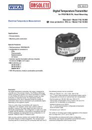
<strong>Temperature</strong> <strong>Transmitter</strong> <strong>T32</strong><br />
For models <strong>T32</strong>.10.xxx, <strong>T32</strong>.11.xxx und <strong>T32</strong>.30.xxx<br />
<strong>WIKA</strong> Technical information • <strong>T32</strong> • Functional safety<br />
Technical<br />
Information<br />
D
<strong>Temperature</strong> <strong>Transmitter</strong> <strong>T32</strong><br />
2<br />
Contents<br />
CPC 8000<br />
1. General information on this handbook 3<br />
1.1 Other applicable documentation 3<br />
1.2 Abbreviations 3<br />
1.3 Relevant standards 4<br />
2. General safety information on SIL/SIS 4<br />
2.1 Definition of Safety Integrity Level (SIL)) 4<br />
2.2 Determination of Safety Integrity Level (SIL) 5<br />
2.3 Definition of Safety Integrity System (SIS)) 6<br />
2.3.1 Safety-related function 6<br />
2.3.2 Failure possibilities 6<br />
2.3.3 Proof test (T Proof ) 6<br />
3. Device-specific safety information 7<br />
3.1 Intended use 7<br />
3.2 Device parameters / Write protection 7<br />
3.3 Inadmissible safety-related use 8<br />
3.4 Installation 8<br />
3.5 Commissioning and periodic tests 8<br />
3.6 Maintenance 9<br />
3.7 Actions in case of errors 9<br />
3.8 Safety-related variables 10<br />
Appendix – SIL Declaration of Conformity 11<br />
Appendix – exida.com, Management summary 12<br />
<strong>WIKA</strong> worldwide 19<br />
<strong>WIKA</strong> Technical information • <strong>T32</strong> • Functional safety<br />
11188546 11/2006 GB
11188546 11/2006 GB<br />
<strong>Temperature</strong> <strong>Transmitter</strong> <strong>T32</strong><br />
1. General information on this handbook<br />
This booklet summarises the <strong>WIKA</strong> temperature transmitters <strong>T32</strong>.10 / <strong>T32</strong>.11 / <strong>T32</strong>.30 with firmware<br />
version 2.0.5 solely as part of a safety-related system. This documentation is valid with the documentation<br />
listed in chapter 1.1. Please also note the safety instructions listed in the operating manual<br />
1.1 Other applicable documentation<br />
Head<br />
version<br />
Rail<br />
version<br />
Hazardous Area<br />
Classification<br />
<strong>WIKA</strong> Technical information • <strong>T32</strong> • Functional safety<br />
Approval – No. Manual Countries<br />
<strong>T32</strong>.1*.**2 <strong>T32</strong>.30.**2 II 1G EEx ia IICT4/T5/T6 DMT 99 ATEX E 007X 2383336 Europe<br />
<strong>T32</strong>.1*.**9 <strong>T32</strong>.30.**9 II 1G EEx nL/nA IIC T4/T5/T6 X -------- 2383336 Europe<br />
<strong>T32</strong>.1*.**6 <strong>T32</strong>.30.**6 Intrinsically safe C<strong>SA</strong> 1248412 2383336 Canada<br />
<strong>T32</strong>.1*.**8 -------- Intrinsically safe FM 3000040 2383336 U<strong>SA</strong><br />
<strong>T32</strong>.1*.**2 <strong>T32</strong>.30.**2 II 1G EEx ia IICT4/T5/T6 20003EC02CP028X INMETRO 2383336 Brasil<br />
<strong>T32</strong>.1*.**2 <strong>T32</strong>.30.**2 II 1G EEx ia IICT4/T5/T6 GYJ04431X, GYJ04432, NEPSI 2383336 China<br />
<strong>T32</strong>.1*.**9 -------- Ex nL/nA IIC T4~T6 GYJ05141U NEPSI 2383336 China<br />
1.2 Abbreviations<br />
Acr. Designation Description<br />
HFT Hardware Fault Tolerance<br />
MTBF Mean Time Between Failures Mean interval between two failures<br />
MTTR Mean Time To Repair<br />
PFD<br />
PFD avg<br />
Probability of Failure on<br />
Demand<br />
Average Probability of<br />
Failure on Demand<br />
SIL Safety Integrity Level<br />
SFF Safe Failure Fraction<br />
T Proof<br />
XooY<br />
Life testing of the safety<br />
function<br />
„X out of Y“<br />
Voting (e.g. 2oo3)<br />
Further relevant abbreviations are listed in the IEC 61508-4 standard.<br />
Capability of a functional unit to continue the execution of the demanded function in<br />
the case of faults or anomalies,<br />
Mean interval between the occurrence of the failure in a device or system and its<br />
repair<br />
Likelihood of dangerous safety function failures occurring on demand<br />
Average likelihood of dangerous safety function failures occurring on demand<br />
The international standard IEC 61508 specifies four discrete safety integrity levels<br />
(SIL 1 to SIL 4). Each level corresponds to a specific probability range with respect<br />
to the failure of a safety function. The higher the integrity level of the safety-related<br />
system, the lower the likelihood of the demanded safety functions not occurring.<br />
Safe Failure Fraction summarises the proportion of failures which lead to a safe<br />
state, and the proportion of failures which will be detected by diagnostic measures<br />
and lead to a defined safety action.<br />
Time interval between the functional test of the safety function.<br />
Classification and description of the safety-related system regarding redundancy<br />
and the selection procedure used. “Y” indicates how often the safety function is<br />
carried out (redundancy). “X” determines how many channels must work properly.<br />
3
<strong>Temperature</strong> <strong>Transmitter</strong> <strong>T32</strong><br />
1.3 Relevant standards<br />
4<br />
CPC 8000<br />
Acr. English German<br />
IEC61508,<br />
Teil 1 bis 7<br />
IEC61511,<br />
Teil 1<br />
Functional safety of electrical/<br />
electronic/programmable electronic<br />
safety-related systems<br />
Target group: Manufacturers, Suppliers<br />
of Devices<br />
Safety Instrumented Systems for the<br />
process industry<br />
Target group: Safety Instrumented<br />
Systems Designers, Integrators and<br />
Users<br />
2. General safety information on SIL/SIS<br />
2.1 Definition of Safety Integrity Level (SIL)<br />
Safety Integrity<br />
Level (SIL<br />
Low demand mode of<br />
operation (PFD avg )<br />
(Average probability of failure<br />
to perform its design function on<br />
demand)<br />
Sicherheitstechnische Systeme für die Prozessindustrie<br />
Zielgruppe: Hersteller und Lieferanten von Geräten<br />
Funktionale Sicherheit sicherheitsbezogener elektrischer/<br />
elektronischer/programmierbarer elektronischer Systeme<br />
Zielgruppe: Planer, Errichter Nutzer<br />
IEC 61508 defines four Safety Integrity Levels (SIL). Each SIL-Level corresponds to the statistical<br />
probability of the failure of a safety-related system. (IEC 61508-4, part 4.5.6). The higher the SIL of<br />
the safety-related system, the higher the probability that the safety-related system will work on demand<br />
and the higher the risk reduction. Or described differently, the higher the safety integrity level of the<br />
safety-related system, the lower the probability that the safety-related system won’t work.<br />
The achievable safety integrity level depends on the following safety-related characteristics:<br />
This value depends on the value of T Proof between the functional test of the safety-related system.<br />
Hardware Fault Tolerance - HFT (Hardware Fault Tolerance - HFT)<br />
Safe Failure Fraction – SFF (Safe Failure Fraction – SFF)<br />
The following table shows the interrelation of the safety integrity level (SIL) with the whole safetyrelated<br />
system (IEC 61508-1, chapter 7.6.2.9).<br />
High demand or<br />
continuous mode of<br />
operation (PFD avg )<br />
(Probability of a dangerous failure<br />
per hour)<br />
Risk Reduction Factor<br />
4 ≥ 10 -5 to ≥ 10 -4 ≥ 10 -9 to ≥ 10 -8 100000 to 10000<br />
3 ≥ 10 -4 to ≥ 10 -3 ≥ 10 -8 to ≥ 10 -7 10000 to 1000<br />
2 ≥ 10 -3 to ≥ 10 -2 ≥ 10 -7 to ≥ 10 -6 1000 to 100<br />
1 ≥ 10 -2 to ≥ 10 -1 ≥ 10 -6 to ≥ 10 -5 100 to 10<br />
<strong>WIKA</strong> Technical information • <strong>T32</strong> • Functional safety<br />
11188546 11/2006 GB
11188546 11/2006 GB<br />
<strong>Temperature</strong> <strong>Transmitter</strong> <strong>T32</strong><br />
If the demand from the process is not higher than once per year, the measuring system can be considered<br />
as subsystem in the low demand mode. Low demand mode also means that the demand on the<br />
safety-related system is not higher than twice the frequency of T Proof .<br />
If “Low Demand Mode” doesn’t apply, the measuring system can be described as a safety-related<br />
system with “High Demand Mode”. (IEC 61508-4, part 3.5.12). “High Demand Mode” means the<br />
demand on the safety-related system is used more than once per year or continuously, or the demand<br />
is higher than twice the frequency of T Proof .<br />
2.2 Determination of Safety Integrity Level (SIL)<br />
The following table shows the SIL of the safety-related system depending on SFF and HFT for type B<br />
subsystems. Type B subsystems typically include instruments with complex components (e.g. microprocessors).<br />
<strong>Temperature</strong> transmitters match the specifications for Type B (IEC 61508-2, part 7.4.3.1.3).<br />
SFF HFT<br />
0 1 (0) (1) 2<br />
< 60 % Not permitted SIL 1 SIL 2<br />
60 to 90 % SIL 1 SIL 2 SIL 3<br />
90 to 99 % SIL 2 SIL 3 SIL 4<br />
< 99 % SIL 3 SIL 4 SIL 4<br />
(1) According to IEC 61511-1, Chapter 11.4.4, the HFT of instruments with complex components can<br />
be decreased by one if the following conditions are met:<br />
The device is proven-in-field<br />
The user can only configure process-related parameters such as measuring range etc.<br />
The configuration level of the device is protected against accidental or unauthorised changes<br />
(Password activated)<br />
The function has a specified SIL of less than 4<br />
<strong>T32</strong>.10 / <strong>T32</strong>.11 / <strong>T32</strong>.30 <strong>Temperature</strong> transmitters meet all these requirements.<br />
<strong>WIKA</strong> Technical information • <strong>T32</strong> • Functional safety<br />
5
<strong>Temperature</strong> <strong>Transmitter</strong> <strong>T32</strong><br />
2.3 Definition of Safety Integrity System (SIS)<br />
6<br />
Sensor<br />
(TempTrans)<br />
CPC 8000<br />
PFDavg is the average probability of failure on demand of the safety-related protection system, which<br />
is the safety integrity failure measure for safety-related protection systems operating in a low demand<br />
mode of operation;<br />
2.3.1 Safety-related function<br />
Logic-System<br />
(e.g. PLC) <br />
Actuator<br />
(e.g. valve)<br />
≤ 35 % ≤ 15 % ≤ 50 %<br />
The analogue signal is transmitted to a series-connected logic unit, e.g. a PLC or an alarm contact,<br />
where it is monitored as to whether it exceeds a maximum value or drops below a minimum value.<br />
The logic unit controls the process e.g. with a signal to an actuator (e.g. valve).<br />
2.3.2 , Failure possibilities<br />
Safe Failure (λsd<br />
und λsu),<br />
(IEC 61508-4, part 3.6.8):<br />
A safe failure occurs if the measuring system switches into the safe state or the error mode without<br />
demand from the process.<br />
Dangerous Failure (λdd) + λdu)), (IEC 61508-4, part 3.6.7):<br />
A dangerous failure occurs if the measuring system switches into a dangerous or functionally<br />
inoperable condition.<br />
Dangerous Undetected Failure (λdu)):<br />
A dangerous undetected failure occurs if the measuring system does not switch into a safe<br />
condition or into the error mode on a demand from the process.<br />
2.3.3 Proof test (T Proof)<br />
According to IEC 61508-4, part 3.8.5, T Proof is defined as periodic tests for exposing errors in a<br />
safety-related system<br />
<strong>WIKA</strong> Technical information • <strong>T32</strong> • Functional safety<br />
11188546 11/2006 GB
11188546 11/2006 GB<br />
<strong>Temperature</strong> <strong>Transmitter</strong> <strong>T32</strong><br />
3. Device-specific safety information<br />
3.1 Intended use<br />
The instrument is a universal, configurable transmitter for resistance thermometers (RTD), thermocouples<br />
(TC) as well as resistance and voltage calibration sources. The temperature transmitter<br />
converts a resistance or voltage value into a proportional current signal between 3.8mA and 20.5mA.<br />
The analogue signal is transmitted to a series-connected logic unit, e.g. a PLC or an alarm contact,<br />
where it is monitored as to whether it exceeds a maximum value or drops below a minimum value.<br />
The temperature transmitter monitors the connected sensor and the internal hardware for errors.<br />
If an error is detected, the transmitter generates both a digital error signal via HART®-Protocol and<br />
an analogue signal at the defined output current (error current for fail low / fail high).<br />
Note: HART® Information must not be used for safety-related operations.<br />
The <strong>T32</strong> generates an error current for the following error conditions.<br />
Sensor burn-out<br />
Sensor short-circuit (only for resistance sensor)<br />
Internal hardware error<br />
Sensor measuring range exceeded or below sensor measuring range<br />
Invalid cold-junction compensation temperature (for thermocouples)<br />
For the error current, the following conditions are defined by NAMUR NE43:<br />
error current, Fail Low: < 3,6 mA (Downscale)<br />
error current, Fail High: < 21,5 mA (Upscale)<br />
If the transmitter delivers the “fail high” or “fail low output current, the user must assume there is a<br />
failure in the system.<br />
The logic unit must be capable of recognising the Fail-High error current (adjustable from 21...22.5 mA)<br />
as well as the Fail-Low error current (3.6 mA). The logic unit must give an appropriate alarm signal.<br />
A measured value is to be assumed in the range of the output current of 7.8 mA < x < 20,5 mA .<br />
The transmitter fulfils, in particular, the requirements for:<br />
functional safety according to IEC 61508/IEC 61511-1<br />
explosion protection (depending on the instrument version)<br />
electromagnetic compatibility according to EN 61326 and NAMUR recommendation NE 21<br />
analogue output error-signalling according to NAMUR recommendation NE 43<br />
Sensor burnout signalling according to NAMUR recommendation NE 89.<br />
3.2 Device parameters / Write protection<br />
Because the process and equipment conditions affect the safety of the whole measuring system, the<br />
instrument parameters have to be set according to the application needs.<br />
The specified limits must be followed; the <strong>T32</strong>’s specifications must not be exceeded.<br />
To protect against inadvertent and/or unauthorised changes in the configuration, alterable parameters<br />
must be write-protected (password activated).<br />
<strong>WIKA</strong> Technical information • <strong>T32</strong> • Functional safety<br />
7
<strong>Temperature</strong> <strong>Transmitter</strong> <strong>T32</strong><br />
8<br />
CPC 8000<br />
The write protection (password) can be used with the following configuration tools:<br />
<strong>WIKA</strong>_<strong>T32</strong> Configuration-Software<br />
AMS<br />
SIMATIC PDM<br />
DTM (Version: DTM Betaversion V1.0.2 January 2003) in combination with FDT/DTM-Standard<br />
user software, e.g PACTware TM<br />
HART®- Handterminal FC375, FC275<br />
and further tools (this list is regulary enhanced)<br />
3.4 Inadmissible safety-related use<br />
Measured value transmission via HART® protocol and the HART® “Multidrop-network” can only be<br />
used for setup, calibration, and diagnostic purposes, not during normal safety-related operation.<br />
3.5 Installation<br />
For installation and mounting instructions please refer to the operating instructions.<br />
3.6 Commissioning and periodic tests<br />
Function tests are intended to demonstrate the correct function of the whole safety-related system,<br />
including all instruments (Sensor, Logic unit, and actuator). Therefore the operability and error current<br />
of the <strong>T32</strong>, as a part of the sensor, must be tested both during commissioning and at reasonable<br />
intervals.<br />
Both the nature of the tests as well as the chosen intervals are the responsibility of the user. The intervals<br />
are set according to the PFDavg values used. (Please refer to the FMEDA report). Usually T proof is<br />
one year or less.<br />
The following tests should only be carried out with write-protection activated, in order to<br />
prevent accidental configuration changes.<br />
Recommended tests:<br />
Simulate a sensor-break and a sensor burnout (sensor burnout only for RTD sensors) and<br />
check the response of the transmitter (error current according to the chosen configuration).<br />
If the temperature sensors are simulated, the following should apply: The input signal must be<br />
generated for the start, middle and end signal of the configured sensor and measuring range.<br />
The corresponding output signal must be monitored (start, middle, span). Recommended tools for<br />
sensor simulation are resistance decades or voltage simulators.<br />
The sensor measuring ranges must be tested both over- and under-range<br />
(e.g. Pt100: -200 < x < 1000°C) and the response of the transmitter checked (error current<br />
according to configuration).<br />
The configuration of the transmitter should be altered using a suitable configuration tool (e.g.<br />
<strong>WIKA</strong> Configuration Software) and the response checked. The transmitter must respond with an<br />
error, due to the activated write-protection.<br />
In some special cases the transmitter logic unit connection can be tested using the “Simulation“ within<br />
the transmitter (i.e. without any sensor or sensor simulation connected). The desired output current of<br />
the transmitter, between 4 mA and 20 mA, can be simulated using the configuration tools described in<br />
Chapter 8.8. To use this feature, the write-protection must be disabled, which means an additional<br />
risk. The methods and procedures for these tests must be documented, as must the test results.<br />
If the outcome of the function test is negative, the whole system must be shut down. The process must<br />
be put into a safe condition using appropriate procedures.<br />
<strong>WIKA</strong> Technical information • <strong>T32</strong> • Functional safety<br />
11188546 11/2006 GB
11188546 11/2006 GB<br />
<strong>Temperature</strong> <strong>Transmitter</strong> <strong>T32</strong><br />
3.7 Maintenance<br />
The transmitter <strong>T32</strong> is maintenance free. The electrical components of the transmitter are mounted in a<br />
plastic case and completely encapsulated. The transmitters therefore have no devices which could be<br />
changed or repaired.<br />
3.8 Actions in case of errors<br />
The cause of malfunctions as well as hints for resolving them are described in the operating instructions.<br />
If malfunctions cannot be resolved, the whole measuring system must be shut down. The process<br />
must be put into a safe condition using appropriate procedures.<br />
Defective instruments must be marked to prevent inadvertent re-use.<br />
Send the faulty instruments back to <strong>WIKA</strong>, along with a description of the cause of the fault. Please use<br />
the Product Return sheet, which can be found at www.wika.de / Service / retoure.<br />
<strong>WIKA</strong> Alexander Wiegand GmbH & Co. KG<br />
Alexander Wiegand Straße<br />
63911 Klingenberg<br />
Tel: 09372 / 132-0<br />
www.wika.de<br />
<strong>WIKA</strong> Technical information • <strong>T32</strong> • Functional safety<br />
9
<strong>Temperature</strong> <strong>Transmitter</strong> <strong>T32</strong><br />
3.9 Safety-related variables<br />
10<br />
<strong>T32</strong>.**.***<br />
(1)<br />
CPC 8000<br />
The failure rates of the electronics were determined using FMEDA according to IEC61508. The failure<br />
rates used in this analysis are the basic failure rates from the Siemens standard SN 29500.<br />
The following assumptions have been made:<br />
All modules are operated in the Low Demand Mode of operation.<br />
External power supply failure rates are not included.<br />
The logic unit must be capable of recognising the Fail-High error current (adjustable from<br />
21...22.5 mA) as well as the Fail-Low error current (3.6 mA) and must give an appropriate alarm<br />
signal.<br />
The values for SFF und PFD avg obtained from the FMEDA-report have been used.<br />
HART®-protocol is only used for setup, calibration, and diagnostic purposes, not during<br />
safety-related normal operation.<br />
The mean ambient temperature during the period of operation is 40°C.<br />
The environmental conditions / stress levels are average for an industrial environment<br />
The temperature transmitter is locked against unintentional and unauthorised change/use<br />
(password protected).<br />
The repair time after a safe failure is 8 hours.<br />
Safety-related figures<br />
Examination for a type B component, with low demand mode and a Hardware Fault Tolerance<br />
(HFT) of 0.<br />
SFF<br />
PFD avg<br />
λ sd<br />
λsu<br />
λdd<br />
λdu<br />
Safe Failure<br />
Fraction<br />
Average Probalility<br />
of dangerous<br />
Failure on demand<br />
Failure rate λ safe<br />
failure detected<br />
Failure rate λ safe<br />
failure undetected<br />
Failure rate λ<br />
dangerous failure<br />
detected<br />
Failure rate λ<br />
dangerous failure<br />
undetected<br />
<strong>T32</strong>.**.***<br />
with thermocouple<br />
connected (4)<br />
(TC)<br />
<strong>T32</strong>.**.***<br />
with 4-wire RTD connected<br />
(4)<br />
(4-wire)<br />
<strong>T32</strong>.**.***<br />
with 2/3-wire RTD<br />
connected (4)<br />
(2-, 3-wire)<br />
> 63 % > 91,75 % > 90,95 % > 76,21 %<br />
9,4-E04 (2) 2,02-E03 (2) 1,02-E03 (2) 2,69-E03 (2)<br />
Note (3) 4.929 FIT 2.158 FIT 1.775 FIT<br />
Note (3) 135 FIT 133 FIT 135 FIT<br />
Note (3) 60 FIT 60 FIT 60 FIT<br />
Note (3) 461 FIT 234 FIT 615 FIT<br />
((1) Without examination of the reliability sensor data.<br />
(2) PFDavg is valid only for the TProof – interval (1 Year), after a recurring function test was carried out<br />
(3) Detailed values (depending on the transmitter configuration) are given in the FMEDA-report<br />
(4) Examination using generic low stress reliability data for the temperature sensor.<br />
<strong>WIKA</strong> Technical information • <strong>T32</strong> • Functional safety<br />
11188546 11/2006 GB
11188546 11/2006 GB<br />
<strong>Temperature</strong> <strong>Transmitter</strong> <strong>T32</strong><br />
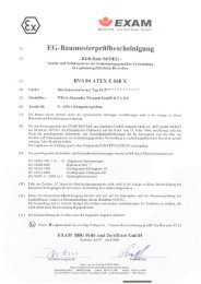
Appendix - SIL Delaration of Conformity<br />
<strong>WIKA</strong> Technical information • <strong>T32</strong> • Functional safety<br />
11
<strong>Temperature</strong> <strong>Transmitter</strong> <strong>T32</strong><br />
12<br />
CPC 8000<br />
Appendix - exida.com, Management summary<br />
Failure Modes, Effects and Diagnostic Analysis<br />
Project:<br />
Digital <strong>Temperature</strong> <strong>Transmitter</strong> <strong>T32</strong> HART<br />
Customer:<br />
<strong>WIKA</strong> – Alexander Wiegand GmbH & Co. KG<br />
Klingenberg<br />
Germany<br />
Contract No.: <strong>WIKA</strong> 02/3-10<br />
Report No.: <strong>WIKA</strong> 02/3-10 R002<br />
Version V2, Revision R1.2, February 2005<br />
Stephan Aschenbrenner<br />
The document was prepared using best effort. The authors make no warranty of any kind and shall not be liable in<br />
any event for incidental or consequential damages in connection with the application of the document.<br />
© All rights on the format of this technical report reserved.<br />
<strong>WIKA</strong> Technical information • <strong>T32</strong> • Functional safety<br />
11188546 11/2006 GB
11188546 11/2006 GB<br />
<strong>Temperature</strong> <strong>Transmitter</strong> <strong>T32</strong><br />
Management summary<br />
This report summarizes the results of the hardware assessment carried out on the Digital<br />
<strong>Temperature</strong> <strong>Transmitter</strong> <strong>T32</strong> HART with firmware version 2.0.4 or 2.0.5. Table 1 gives an<br />
overview of the different types that belong to the considered Digital <strong>Temperature</strong> <strong>Transmitter</strong><br />
<strong>T32</strong> HART.<br />
The hardware assessment consists of a Failure Modes, Effects and Diagnostics Analysis<br />
(FMEDA). A FMEDA is one of the steps taken to achieve functional safety assessment of a<br />
device per IEC 61508. From the FMEDA, failure rates are determined and consequently the<br />
Safe Failure Fraction (SFF) is calculated for the device. For full assessment purposes all<br />
requirements of IEC 61508 must be considered.<br />
Table 1: Version overview<br />
<strong>T32</strong>.10 Digital <strong>Temperature</strong> <strong>Transmitter</strong>, head mounted (standard)<br />
<strong>T32</strong>.11 Digital <strong>Temperature</strong> <strong>Transmitter</strong>, head mounted (high ambient temperature stability)<br />
<strong>T32</strong>.30 Digital <strong>Temperature</strong> <strong>Transmitter</strong>, rail mounted (standard)<br />
For safety applications only the 4..20 mA output was considered.<br />
The failure rates used in this analysis are the basic failure rates from the Siemens standard<br />
SN 29500.<br />
According to table 2 of IEC 61508-1 the average PFD for systems operating in low demand<br />
mode has to be ≥10 -2 to < 10 -1 for SIL 1 safety functions and ≥10 -3 to < 10 -2 for SIL 2 safety<br />
functions. A generally accepted distribution of PFDAVG values of a SIF over the sensor part, logic<br />
solver part, and final element part assumes that 35% of the total SIF PFDAVG value is caused by<br />
the sensor part.<br />
For a SIL 1 application the total PFDAVG value of the SIF should be smaller than 1,00E-01,<br />
hence the maximum allowable PFDAVG value for the sensor assembly consisting of <strong>T32</strong> and a<br />
thermocouple or RTD supplied with <strong>T32</strong> would then be 3,50E-02.<br />
For a SIL 2 application the total PFDAVG value of the SIF should be smaller than 1,00E-02,<br />
hence the maximum allowable PFDAVG value for the sensor assembly consisting of <strong>T32</strong> and a<br />
thermocouple or RTD supplied with <strong>T32</strong> would then be 3,50E-03.<br />
The Digital <strong>Temperature</strong> <strong>Transmitter</strong> <strong>T32</strong> HART is considered to be a Type B 1 component with<br />
a hardware fault tolerance of 0.<br />
For Type B components the SFF has to be between 60% and 90% for SIL 1 (sub-) systems and<br />
between 90% and 99% for SIL 2 (sub-) systems with a hardware fault tolerance of 0 according<br />
to table 2 of IEC 61508-2.<br />
Assuming that a connected logic solver can detect both over-range (fail high) and under-range<br />
(fail low), high and low failures can be classified as safe detected failures or dangerous detected<br />
failures depending on whether the Digital <strong>Temperature</strong> <strong>Transmitter</strong> <strong>T32</strong> HART is used in an<br />
application for “low level monitoring” (MIN), “high level monitoring” (MAX) or “range monitoring”.<br />
For these applications the following tables show how the above stated requirements are fulfilled<br />
for the worst case configuration of the Digital <strong>Temperature</strong> <strong>Transmitter</strong> <strong>T32</strong> HART.<br />
1 Type B component: “Complex” component (using micro controllers or programmable logic); for details see<br />
7.4.3.1.3 of IEC 61508-2.<br />
© exida.com GmbH wika 02-3-10 r002 v2 r1.2, February 8, 2005<br />
Stephan Aschenbrenner Page 2 of 5<br />
<strong>WIKA</strong> Technical information • <strong>T32</strong> • Functional safety<br />
13
<strong>Temperature</strong> <strong>Transmitter</strong> <strong>T32</strong><br />
14<br />
CPC 8000<br />
Table 2: Summary for <strong>T32</strong> (worst case configuration) – Failure rates<br />
Failure category (Failure rates in FIT)<br />
Fail High (detected by the logic solver)<br />
Fail detected (int. diag.) 137<br />
Fail high (inherently) 38<br />
Fail Low (detected by the logic solver)<br />
Fail detected (int. diag.) 137<br />
Fail-safe state =<br />
“fail high”<br />
Fail-safe state =<br />
“fail low”<br />
© exida.com GmbH wika 02-3-10 r002 v2 r1.2, February 8, 2005<br />
Stephan Aschenbrenner Page 3 of 5<br />
175<br />
Fail low (inherently) 60 60<br />
Fail Dangerous Undetected 215 215<br />
No Effect 135 135<br />
MTBF = MTTF + MTTR 195 years 195 years<br />
<strong>Transmitter</strong> configured fail-safe state = “fail high” – Failure rates according to IEC 61508<br />
Failure Categories λsd λsu λdd λdu SFF DCS 2 DCD ²<br />
λlow = λsd<br />
λhigh = λdd<br />
λlow = λdd<br />
λhigh = λsd<br />
λlow = λsd<br />
λhigh = λsd<br />
60 FIT 135 FIT 175 FIT 215 FIT 63% 30% 44%<br />
175 FIT 135 FIT 60 FIT 215 FIT 63% 56% 21%<br />
235 FIT 135 FIT 0 FIT 215 FIT 63% 63% 0%<br />
<strong>Transmitter</strong> configured fail-safe state = “fail low” – Failure rates according to IEC 61508<br />
Failure Categories λsd λsu λdd λdu SFF DCS ² DCD ²<br />
λlow = λsd<br />
λhigh = λdd<br />
λlow = λdd<br />
λhigh = λsd<br />
λlow = λsd<br />
λhigh = λsd<br />
197 FIT 135 FIT 38 FIT 215 FIT 63% 59% 15%<br />
38 FIT 135 FIT 197 FIT 215 FIT 63% 21% 47%<br />
235 FIT 135 FIT 0 FIT 215 FIT 63% 63% 0%<br />
It is important to realize that the “don’t care” failures are included in the “safe undetected” failure<br />
category according to IEC 61508. Note that these failures on its own will not affect system<br />
reliability or safety, and should not be included in spurious trip calculations.<br />
2 DC means the diagnostic coverage (safe or dangerous) of the safety logic solver for the Digital<br />
<strong>Temperature</strong> <strong>Transmitter</strong> <strong>T32</strong> HART.<br />
38<br />
197<br />
<strong>WIKA</strong> Technical information • <strong>T32</strong> • Functional safety<br />
11188546 11/2006 GB
11188546 11/2006 GB<br />
<strong>Temperature</strong> <strong>Transmitter</strong> <strong>T32</strong><br />
Table 3: Summary for <strong>T32</strong> (worst case configuration) – PFDAVG values<br />
T[Proof] = 1 year T[Proof] = 5 years T[Proof] = 10 years<br />
PFDAVG = 9,41E-04 PFDAVG = 4,69E-03 PFDAVG = 9,36E-03<br />
A complete temperature sensor assembly consisting of <strong>T32</strong> and a closely coupled<br />
thermocouple or cushioned RTD supplied with <strong>T32</strong> can be modeled by considering a series<br />
subsystem where a failure occurs if there is a failure in either component. For such a system,<br />
failure rates are added.<br />
Section 5.5 gives typical failure rates and failure distributions for thermocouples and RTDs<br />
which were the basis for the following tables.<br />
Assuming that <strong>T32</strong> is programmed to drive its output high on detected failures of the<br />
thermocouple or RTD (λlow = λdd, λhigh = λsd), the failure rate contribution or the PFDAVG value for<br />
the thermocouple or RTD in a low stress environment is as follows:<br />
Table 4: Summary for the sensor assembly <strong>T32</strong> / thermocouple in low stress environment<br />
T[Proof] = 1 year T[Proof] = 5 years T[Proof] = 10 years SFF<br />
PFDAVG = 2,02E-03 PFDAVG = 1,01E-02 PFDAVG = 2,02E-02 > 91%<br />
λsd = 4929 FIT<br />
λsu = 135 FIT<br />
λdd = 60 FIT<br />
λdu = 461 FIT<br />
Table 5: Summary for the sensor assembly <strong>T32</strong> / 4-wire RTD in low stress environment<br />
T[Proof] = 1 year T[Proof] = 5 years T[Proof] = 10 years SFF<br />
PFDAVG = 1,02E-03 PFDAVG = 5,12E-03 PFDAVG = 1,02E-02 > 90%<br />
λsd = 2158 FIT<br />
λsu = 133 FIT<br />
λdd = 60 FIT<br />
λdu = 234 FIT<br />
Table 6: Summary for the sensor assembly <strong>T32</strong> / 2/3-wire RTD in low stress environment<br />
T[Proof] = 1 year T[Proof] = 5 years T[Proof] = 10 years SFF<br />
PFDAVG = 2,69E-03 PFDAVG = 1,35E-02 PFDAVG = 2,69E-02 > 76%<br />
λsd = 1775 FIT<br />
λsu = 135 FIT<br />
λdd = 60 FIT<br />
λdu = 615 FIT<br />
© exida.com GmbH wika 02-3-10 r002 v2 r1.2, February 8, 2005<br />
Stephan Aschenbrenner Page 4 of 5<br />
<strong>WIKA</strong> Technical information • <strong>T32</strong> • Functional safety<br />
15
11188546 11/2006 GB<br />
<strong>Temperature</strong> <strong>Transmitter</strong> <strong>T32</strong><br />
The boxes marked in yellow ( ) mean that the calculated PFDAVG values are within the<br />
allowed range for SIL 2 according to table 2 of IEC 61508-1 but do not fulfill the requirement to<br />
not claim more than 35% of this range, i.e. to be better than or equal to 3,50E-03. The boxes<br />
marked in green ( ) mean that the calculated PFDAVG values are within the allowed range for<br />
SIL 2 according to table 2 of IEC 61508-1 and table 3.1 of ANSI/I<strong>SA</strong>–84.01–1996 and do fulfill<br />
the requirement to not claim more than 35% of this range, i.e. to be better than or equal to<br />
3,50E-03. The boxes marked in red ( ) mean that the calculated PFDAVG values do not fulfill<br />
the requirement for SIL 2 according to table 2 of IEC 61508-1.<br />
Where the Safe Failure Fraction (SFF) is between 60% and 90% the SIL 1 architectural<br />
constraints requirements of table 3 of IEC 61508-2 for Type B subsystems with a Hardware<br />
Fault Tolerance (HFT) of 0 are fulfilled.<br />
Where the Safe Failure Fraction (SFF) is above 90% the SIL 2 architectural constraints<br />
requirements of table 3 of IEC 61508-2 for Type B subsystems with a Hardware Fault Tolerance<br />
(HFT) of 0 are fulfilled.<br />
The hardware assessment has shown that the Digital <strong>Temperature</strong> <strong>Transmitter</strong> <strong>T32</strong> HART<br />
with 4..20 mA output has a PFDAVG within the allowed range for SIL 1 according to table 2<br />
of IEC 61508-1 and table 3.1 of ANSI/I<strong>SA</strong>–84.01–1996 and a Safe Failure Fraction (SFF) of<br />
more than 63%.<br />
A user of the Digital <strong>Temperature</strong> <strong>Transmitter</strong> <strong>T32</strong> HART can utilize these failure rates along<br />
with the failure rates for the temperature sensing device in a probabilistic model of a safety<br />
instrumented function (SIF) to determine suitability in part for safety instrumented system (SIS)<br />
usage in a particular safety integrity level (SIL). A full table of failure rates for different operating<br />
conditions is presented in section 5.1 to 5.4 along with all assumptions and temperature sensing<br />
device data.<br />
© exida.com GmbH wika 02-3-10 r002 v2 r1.2, February 8, 2005<br />
Stephan Aschenbrenner Page 5 of 5<br />
<strong>WIKA</strong> Technical information • <strong>T32</strong> • Functional safety<br />
16
<strong>Temperature</strong> <strong>Transmitter</strong> <strong>T32</strong><br />
17<br />
1 Purpose and Scope<br />
CPC 8000<br />
Generally three options exist when doing an assessment of sensors, interfaces and/or final<br />
elements.<br />
Option 1: Hardware assessment according to IEC 61508<br />
Option 1 is a hardware assessment by exida.com according to the relevant functional safety<br />
standard(s) like DIN V VDE 0801, IEC 61508 or EN 954-1. The hardware assessment consists<br />
of a FMEDA to determine the fault behavior and the failure rates of the device, which are then<br />
used to calculate the Safe Failure Fraction (SFF) and the average Probability of Failure on<br />
Demand (PFDAVG).<br />
This option for pre-existing hardware devices shall provide the safety instrumentation engineer<br />
with the required failure data as per IEC 61508 / IEC 61511 and does not consist of an<br />
assessment of the software development process<br />
Option 2: Hardware assessment with proven-in-use consideration according to IEC 61508 /<br />
IEC 61511<br />
Option 2 is an assessment by exida.com according to the relevant functional safety standard(s)<br />
like DIN V VDE 0801, IEC 61508 or EN 954-1. The hardware assessment consists of a FMEDA<br />
to determine the fault behavior and the failure rates of the device, which are then used to<br />
calculate the Safe Failure Fraction (SFF) and the average Probability of Failure on Demand<br />
(PFDAVG). In addition this option consists of an assessment of the proven-in-use documentation<br />
of the device and its software including the modification process.<br />
This option for pre-existing programmable electronic devices shall provide the safety<br />
instrumentation engineer with the required failure data as per IEC 61508 / IEC 61511 and justify<br />
the reduced fault tolerance requirements of IEC 61511 for sensors, final elements and other PE<br />
field devices.<br />
Option 3: Full assessment according to IEC 61508<br />
Option 3 is a full assessment by exida.com according to the relevant application standard(s)<br />
like IEC 61511 or EN 298 and the necessary functional safety standard(s) like DIN V VDE 0801,<br />
IEC 61508 or EN 954-1. The full assessment extends option 1 by an assessment of all fault<br />
avoidance and fault control measures during hardware and software development.<br />
This option is most suitable for newly developed software based field devices and<br />
programmable controllers to demonstrate full compliance with IEC 61508 to the end-user.<br />
This assessment shall be done according to option 1.<br />
This document shall describe the results of the assessment carried out on the Digital<br />
<strong>Temperature</strong> <strong>Transmitter</strong> <strong>T32</strong> HART with firmware version 2.0.4 or 2.0.5. Table 1 gives an<br />
overview of the series and explains the differences between the different types.<br />
It shall be assessed whether the transmitter meets the average Probability of Failure on<br />
Demand (PFDAVG) requirements and the architectural constraints for SIL 1 sub-systems<br />
according to IEC 61508. It does not consider any calculations necessary for proving intrinsic<br />
safety.<br />
© exida.com GmbH wika 02-3-10 r002 v2 r1.2, February 8, 2005<br />
Stephan Aschenbrenner Page 2 of 2<br />
<strong>WIKA</strong> Technical information • <strong>T32</strong> • Functional safety<br />
11188546 11/2006 GB
11188546 11/2006 GB<br />
<strong>Temperature</strong> <strong>Transmitter</strong> <strong>T32</strong><br />
<strong>WIKA</strong> worldwide<br />
Europe<br />
Austria<br />
<strong>WIKA</strong> Messgerätevertrieb<br />
Ursula Wiegand<br />
GmbH & Co. KG<br />
1230 Wien<br />
Phone: (+43) 1-86 91 631<br />
Fax: (+43) 1-86 91 634<br />
E-mail: info@wika.at<br />
www.wika.at<br />
Benelux<br />
<strong>WIKA</strong> Benelux<br />
6101 WX Echt<br />
Phone: (+31) 475-535 500<br />
Fax: (+31) 475-535 446<br />
E-mail: info@wika.nl<br />
www.wika.nl<br />
Bulgaria<br />
<strong>WIKA</strong> Bulgaria EOOD<br />
1309 Sofia<br />
Phone: (+359) 2 82138-10<br />
Fax: (+359) 2 82138-13<br />
E-mail: t.antonov@wika.bg<br />
Finland<br />
<strong>WIKA</strong> Finland Oy<br />
00210 Helsinki<br />
Phone: (+358) 9-682 49 20<br />
Fax: (+358) 9-682 49 270<br />
E-mail: info@wika.fi<br />
www.wika.fi<br />
France<br />
<strong>WIKA</strong> Instruments s.a.r.l.<br />
95610 Eragny-sur-Oise<br />
Phone: (+33) 1-34 30 84 84<br />
Fax: (+33) 1-34 30 84 94<br />
E-mail: info@wika.fr<br />
www.wika.fr<br />
Germany<br />
<strong>WIKA</strong><br />
Alexander Wiegand<br />
GmbH & Co. KG<br />
63911 Klingenberg<br />
Phone: (+49) 93 72-13 20<br />
Fax: (+49) 93 72-13 24 06<br />
E-mail: info@wika.de<br />
www.wika.de<br />
Italy<br />
<strong>WIKA</strong> Italiana SRL<br />
20020 Arese (Milano)<br />
Phone: (+39) 02-93 86 11<br />
Fax: (+39) 02-93 86 174<br />
E-mail: info@wika.it<br />
www.wika.it<br />
Poland<br />
Kujawska Fabryka Manometrow<br />
-KFM S.A.<br />
87-800 Wloclawek<br />
Phone: (+48) 542 30 11 00<br />
Fax: (+48) 542 30 11 01<br />
E-mail: info@manometry.com.pl<br />
www.manometry.com.pl<br />
Romania<br />
<strong>WIKA</strong> Instruments S.R.L.<br />
Bucuresti, Sector 5<br />
Phone: (+40) 21-456 31 38<br />
Fax: (+40) 21-456 31 37<br />
E-mail: m.anghel@wika.ro<br />
Russia<br />
ZAO „<strong>WIKA</strong> MERA“<br />
127015 Moscow<br />
Phone: (+7) 495-786 21 25<br />
Fax: (+7) 495-786 21 23<br />
E-mail: info@wika.ru<br />
www.wika.ru<br />
Serbia<br />
<strong>WIKA</strong> Merna Tehnika d.o.o.<br />
11060 Beograd<br />
Phone: (+381) 11 27 63 722<br />
Fax: (+381) 11 75 36 74<br />
E-mail: info@wika.co.yu<br />
www.wika.co.yu<br />
Spain<br />
Instrumentos <strong>WIKA</strong>, S.A.<br />
08280 Sabadell (Barcelona)<br />
Phone: (+34) 90-290 25 77<br />
Fax: (+34) 93-393 86 66<br />
E-mail: info@wika.es<br />
www.wika.es<br />
Switzerland<br />
MANOMETER AG<br />
6285 Hitzkirch<br />
Phone: (+41) 41-919 72 72<br />
Fax: (+41) 41-919 72 73<br />
E-mail: info@manometer.ch<br />
www.manometer.ch<br />
Ukraine<br />
<strong>WIKA</strong> Pribor GmbH<br />
83016 Donetsk<br />
Phone: (+38) 062 345 34 16<br />
Fax: (+38) 062 345 34 16<br />
E-mail: info@wika.donetsk.ua<br />
www.wika.donetsk.ua<br />
United Kingdom<br />
<strong>WIKA</strong> Instruments Ltd<br />
Merstham, Redhill RH13LG<br />
Phone: (+44) 17 37 64 40 08<br />
Fax: (+44) 17 37 64 44 03<br />
E-mail: info@wika.co.uk<br />
www.wika.co.uk<br />
North America<br />
Canada<br />
<strong>WIKA</strong> Instruments Ltd.<br />
Head Office<br />
Edmonton, Alberta, T6N 1C8<br />
Phone: (+1) 780-463 70 35<br />
Fax: (+1) 780-462 00 17<br />
E-mail: info@wika.ca<br />
www.wika.ca<br />
Mexico<br />
Instrumentos <strong>WIKA</strong> Mexico S.A.<br />
de C.V.<br />
01219 Mexico D.F.<br />
Phone: (+52) 555 020 53 00<br />
Fax: (+52) 555 020 53 01<br />
E-Mail ventas@wika.com.mx<br />
www.wika.com.mx<br />
U<strong>SA</strong><br />
<strong>WIKA</strong> Instrument Corporation<br />
Lawrenceville, GA 30043<br />
Phone: (+1) 770-513 82 00<br />
Fax: (+1) 770-338 51 18<br />
E-mail: info@wika.com<br />
www.wika.com<br />
<strong>WIKA</strong> Technical information • <strong>T32</strong> • Functional safety<br />
South America<br />
<strong>Argentina</strong><br />
<strong>WIKA</strong> <strong>Argentina</strong> S.A.<br />
Buenos Aires<br />
Phone: (+54-11) 4730 18 00<br />
Fax: (+54-11) 4761 00 50<br />
E-mail: info@wika.com.ar<br />
www.wika.com.ar<br />
Brazil<br />
<strong>WIKA</strong> do Brasil Ind. e Com.<br />
Ltda.<br />
CEP 18560-000 Iperó - SP<br />
Phone: (+55) 15-3266 16 55<br />
Fax: (+55) 15-3266 16 50<br />
E-mail: marketing@wika.com.br<br />
www.wika.com.br<br />
Africa/Middle East<br />
Egypt<br />
<strong>WIKA</strong> Alexander Wiegand<br />
GmbH & Co. KG<br />
Makram Ebaid<br />
Nasr City, Cairo<br />
Phone: (+20) 2 - 273 31 40<br />
Fax: (+20) 2 - 273 31 40<br />
E-mail: ahmed.azab@wika.de<br />
Iran<br />
<strong>WIKA</strong> Instrumentation Pars<br />
(KFZ) Ltd.<br />
Anahita Tower, Tehran<br />
Phone: (+98-21) 8878 3514-17<br />
Fax: (+98-21) 8887 8593<br />
E-mail: info@wika.ir<br />
www.wika.ir<br />
South Africa<br />
<strong>WIKA</strong> Instruments (Pty.) Ltd.<br />
Gardenview, Johannesburg<br />
2047<br />
Phone: (+27) 11-621 00 00<br />
Fax: (+27) 11-621 00 59<br />
E-mail: sales@wika.co.za<br />
www.wika.co.za<br />
United Arab Emirates<br />
<strong>WIKA</strong> Middle East FZE<br />
Jebel Ali, Dubai<br />
Phone: (+971) 4 - 883 90 90<br />
Fax: (+971) 4 - 883 91 98<br />
E-mail: wikame@emirates.net.ae<br />
Asia<br />
China<br />
<strong>WIKA</strong> International Trading<br />
(Shanghai) Co., Ltd.<br />
200001 Shanghai<br />
Phone: (+86) 21 - 53 85 25 73<br />
Fax: (+86) 21 - 53 85 25 75<br />
E-mail: wikash@online.sh.cn<br />
www.wika.com.cn<br />
India<br />
<strong>WIKA</strong> Instruments India Pvt. Ltd.<br />
Village Kesnand, Wagholi<br />
Pune - 412 207<br />
Phone: (+91) 20 - 27 05 29 01<br />
Fax: (+91) 20 - 27 05 19 25<br />
E-mail: sales@wika.co.in<br />
www.wika.co.in<br />
Japan<br />
<strong>WIKA</strong> Japan K. K.<br />
Tokyo 105-0023<br />
Phone: (+81) 3-54 39 66 73<br />
Fax: (+81) 3-54 39 66 74<br />
E-mail: t-shimane@wika.co.jp<br />
Kazakhstan<br />
TOO <strong>WIKA</strong> Kazakhstan<br />
050050 Almaty<br />
Phone: (+7) 32 72 33 08 48<br />
Fax: (+7) 32 72 78 99 05<br />
E-mail:<br />
wika-kazakhstan@nursat.kz<br />
Korea<br />
<strong>WIKA</strong> Korea Ltd.<br />
Seoul 153-023<br />
Phone: (+82) 2 - 8 69 05 05<br />
Fax: (+82) 2 - 8 69 05 25<br />
E-mail: info@wika.co.kr<br />
Malaysia<br />
<strong>WIKA</strong> Instrumentation (M)<br />
Sdn. Bhd.<br />
Selangor Darul Ehsan<br />
Phone: (+60) 3 - 56 36 88 58<br />
Fax: (+60) 3 - 56 36 90 72<br />
E-mail: info@wika.com.my<br />
www.wika.com.my<br />
Singapore<br />
<strong>WIKA</strong> Instrumentation Pte. Ltd.<br />
569625 Singapore<br />
Phone: (+65) 68 44 55 06<br />
Fax: (+65) 68 44 55 07<br />
E-mail: info@wika.com.sg<br />
www.wika.com.sg<br />
Taiwan<br />
<strong>WIKA</strong> Instrumentation Taiwan<br />
Ltd.<br />
Pinjen, Taoyuan<br />
Phone: (+886) 034 20 60 52<br />
Fax: (+886) 034 90 00 80<br />
E-mail: info@wika.com.tw<br />
www.wika.com.tw<br />
Australia<br />
Australia<br />
<strong>WIKA</strong> Australia Pty. Ltd.<br />
Rydalmere, NSW 2116<br />
Phone: (+61) 2 - 88 45 52 22<br />
Fax: (+61) 2 - 96 84 47 67<br />
E-mail: sales@wika.com.au<br />
www.wika.com.au<br />
18
<strong>WIKA</strong> Alexander Wiegand GmbH & Co. KG<br />
Alexander-Wiegand-Straße 30<br />
63911 Klingenberg Germany<br />
Phone (+49) 93 72/132-0<br />
Fax (+49) 93 72/132-406<br />
E-Mail info@wika.de<br />
www.wika.de