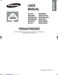
RFG29PHDBP RFG29PHDPN RFG29PHDRS RFG29PHDWP ...
RFG29PHDBP RFG29PHDPN RFG29PHDRS RFG29PHDWP ...
RFG29PHDBP RFG29PHDPN RFG29PHDRS RFG29PHDWP ...

Create successful ePaper yourself
Turn your PDF publications into a flip-book with our unique Google optimized e-Paper software.
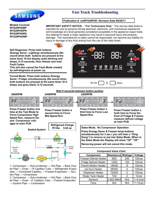
Models Covered:<br />
<strong>RFG29PHDBP</strong><br />
<strong>RFG29PHDPN</strong><br />
<strong>RFG29PHDRS</strong><br />
<strong>RFG29PHDWP</strong><br />
Self Diagnosis: Press both buttons<br />
(Energy Saver– Lighting) simultaneously (No<br />
sound when both buttons are pressed at the<br />
same time) ‟til the display quits blinking and<br />
beeps, 8-12 seconds, then release and read<br />
Fault Codes.<br />
This will also cancel the Fault Mode created<br />
by self-diagnosis at power up.<br />
Forced Mode: Press both buttons (Energy<br />
Saver– Fridge) simultaneously (No sound when<br />
both buttons are pressed at the same time) „til it<br />
beeps and goes blank, 8-12 seconds<br />
Fast Track Troubleshooting<br />
IMPORTANT SAFETY NOTICE – “For Technicians Only” This service data sheet is<br />
intended for use by persons having electrical, electronic, and mechanical experience<br />
and knowledge at a level generally considered acceptable in the appliance repair trade.<br />
Any attempt to repair a major appliance may result in personal injury and property<br />
damage. The manufacturer or seller cannot be responsible, nor assume any liability for<br />
injury or damage of any kind arising from the use of this data sheet.<br />
Wait 5 seconds between button pushes<br />
3600RPM 2450RPM 2200RPM<br />
Press Freezer button one<br />
time at the Test Mode to<br />
Force Compressor High<br />
Speed Run, measure fan<br />
and Compressor voltages<br />
at main PCB<br />
Sealed System<br />
Press Freezer button a<br />
second time to Force<br />
Mid Speed Run<br />
Refrigerant Charge<br />
R134a 5.64 oz.<br />
1. Compressor → Sub-condenser → Hot Pipe → Back Cluster<br />
Pipe → Dryer → R Capillary Tube → Refrigerator Evaporator<br />
→ Connected Capillary → Freezer Evaporator → Suction<br />
Pipe → Compressor<br />
2. Compressor → Sub-condenser → Hot Pipe → Back Cluster<br />
Pipe → Dryer →F Capillary Tube → Freezer Evaporator<br />
→ Suction Pipe → Compressor<br />
Publication # nwRFG29PHD Revision Date 09/28/11<br />
Press Freezer button a<br />
third time to Force Low<br />
Speed Run<br />
Sales Mode, No Compressor Operation<br />
Component Value Chart<br />
Press Freezer button a<br />
forth time to Force Defrost<br />
of Fridge & Freezer,<br />
measure defrost voltage<br />
at main PCB<br />
Press Energy Saver & Freezer temp buttons<br />
simultaneously for 3 sec ( you will hear a “Ding<br />
Dong”) to remove or put into Sales Mode. When in<br />
the Sales Mode the Display will show "OF" "OF"<br />
Removing power will not cancel this mode.<br />
Component Resistance Wattage Voltage<br />
Freezer Defrost Heater 60Ω 240 120vac<br />
Fridge Defrost Heater 120Ω 120 120vac<br />
French Mullion Heater 1800Ω 8 120vac<br />
Ice Duct Heater 3600Ω 4 120vac<br />
Dispenser Heater 7200Ω 2 120vac<br />
Water Tank Heater 72Ω 2 12vdc<br />
Sensors 2.5kΩ-89kΩ N/A 1~4.5vdc<br />
Fans N/A N/A 7~12vdc
Heat Release Ice production Explanation<br />
38 minutes after the water fill is complete, the control<br />
board will check the temperature of the eject Thermistor,<br />
on the Ice Maker Head, if the Thermistor reads a temperature<br />
lower than 18.5 degrees for more than 5 seconds,<br />
then the ice production process is completed. The<br />
Ice maker will harvest if the ice bucket is not sensed as<br />
full. If a Fault Mode is detected with the Ice Maker operation,<br />
the Ice Maker stops working for 3 hours. Which<br />
means, the Ice Maker checks the operation every 3<br />
hours until it works properly.<br />
DC FAN MOTORS<br />
Brushless DC Fan motors are used to save energy. The fans operate at two speeds. Fan speed information is read by<br />
the Main PCB. If the fan speed exceeds 600 RPM or the speed is too slow, or stopped the fan drive circuit is disabled,<br />
After 10 seconds the circuit tries again with 3 seconds of DC voltage If the fan continues this activity for 5 cycles, 10<br />
seconds off 3 seconds on, the fan drive circuit is disabled for 10 minutes.<br />
TO TEST THE FAN CIRCUIT VOLTAGE.<br />
Power off and back on to check the DC voltage to the motor, wait from 10 to 60 seconds for the fan voltage to kick in,<br />
and then check fan voltage, the average reading is 9 VDC. If you get 3 seconds of voltage every 10 seconds for the 5<br />
fan power up cycles, then the Main PCB is good.<br />
NOTE: You may need to put unit in FORCED FREEZE mode to activate the fans/compressor.<br />
If the fan blade is blocked by ice, then defrost and check the motor again, after removing power from the unit.<br />
If the evaporator is ice blocked and thus blocking the air flow, the fan will over RPM and is stopped. Remove ice and<br />
check the motor again. If everything is clear around the fan blade then the motor would be at fault. Continuous fan errors<br />
will be displayed on the front panel display. PLEASE NOTE: The door switches control the evaporator fan motors. Have<br />
them closed to test the motors. Delay time 10 – 60 seconds.<br />
Heat Release Ice Makers<br />
Heat Release I/M Test Mode<br />
Press and hold the ICE TEST S/W for at least 1.5sec, the<br />
harvest function will start. If the ice maker Thermistor is below<br />
0 degrees the Ice maker heater turns on for about 2 minutes.<br />
If the temperature exceeds 0 degrees, Ice maker<br />
heater turns on for 30 seconds. After the Ice maker heater<br />
turns on for 30 seconds, the heater turns off and then Ice<br />
maker harvest motor turns on. The motor will rotate in right<br />
direction for about 3 minutes, after this, water supply valve is<br />
turned on, then the valve is turned off, the test mode is completed.<br />
If the above operation is not carried out within 6 minutes,<br />
it will go into a fault mode.<br />
FREEZER TEMPERATURE CONTROL BY THE ICE MAKER<br />
Interior Temperature of the freezer will be set to -14 degrees Fahrenheit until the ice bucket is full. When the ice<br />
bucket is full, the freezer will maintain original set temperature. Also, whenever the ice is used, the freezer will<br />
again set to -14 degrees Fahrenheit. Selecting "Ice Off” will allow the freezer to be controlled by the set temperature.<br />
If water is not hooked up, the freezer will always be at –14 unless “Ice Off” is selected.<br />
Temperature/Resistance/Voltage Chart for Samsung Refrigerators Sensors<br />
Temp. (Ω) Volts Temp. (Ω) Volts Temp. (Ω) Volts Temp. (Ω) Volts<br />
-29.2°F 64227 4.326 1.4°F 28021 3.685 32.0°F 13290 2.853 62.6°F 6771 2.019<br />
-27.4°F 61012 4.296 3.2°F 26760 3.64 33.8°F 12749 2.802 64.4°F 6521 1.974<br />
-25.6°F 57977 4.264 5.0°F 25562 3.594 35.6 °F 12233 2.751 66.2°F 6281 1.929<br />
-23.8°F 55112 4.232 6.8°F 24425 3.548 37.4 °F 11741 2.7 68.0°F 6052 1.885<br />
-22.0°F 52406 4.199 8.6°F 23345 3.501 39.2 °F 11271 2.649 69.8°F 5832 1.842<br />
-20.2°F 49848 4.165 10.4°F 22320 3.453 41.0°F 10823 2.599 71.6°F 5621 1.799<br />
-18.4°F 47431 4.129 12.2°F 21345 3.405 42.8°F 10395 2.548 75.2°F 5225 1.716<br />
-16.6°F 45146 4.093 14.0°F 20418 3.356 44.6°F 9986 2.498 77.0°F 5000 1.675<br />
-14.8°F 42984 4.056 15.8°F 19537 3.307 46.4°F 9596 2.449 78.8°F 4861 1.636<br />
-13.0°F 40938 4.018 17.6°F 18698 3.258 48.2°F 9223 2.399 80.6°F 4690 1.596<br />
-11.2°F 39002 3.98 19.4°F 17901 3.208 50.0°F 8867 2.35 86.0°F 4218 1.483<br />
-9.4°F 37169 3.94 21.2°F 17142 3.158 51.8°F 8526 2.301 87.8°F 4072 1.447<br />
-7.6°F 35433 3.899 23.0°F 16419 3.107 53.6°F 8200 2.253 89.6°F 3933 1.412<br />
-5.8°F 33788 3.858 24.8°F 15731 3.057 55.4°F 7888 2.205 91.4°F 3799 1.377<br />
-4.0°F 32230 3.816 26.6°F 15076 3.006 57.2°F 7590 2.158 95.0°F 3547 1.309<br />
-2.2°F 30752 3.773 28.4°F 14452 2.955 59.0°F 7305 2.111 96.8°F 3428 1.277<br />
-0.4°F 29350 3.729 30.2°F 13857 2.904 60.8°F 7032 2.064 100.4°F 3204 1.213
Error Code Item Trouble contents<br />
1 E<br />
2 E<br />
4 E<br />
5 E<br />
6 E<br />
7 E<br />
FZ SENSOR ERROR<br />
R SENSOR ERROR<br />
FZ DEF SENSOR ERROR<br />
R DEF SENSOR ERROR<br />
AMBIENT-SENSOR ERROR<br />
FLEX SENSOR ERROR<br />
13 E HUMIDITY-SENSOR ERROR<br />
14 E<br />
15 E<br />
21 E<br />
22 E<br />
23 E<br />
IM SENSOR ERROR<br />
ICE RM SENSOR ERROR<br />
FZ FAN ERROR<br />
R FAN ERROR<br />
C-FAN ERROR<br />
24 E FZ DEF FUNCTION ERROR<br />
25 E<br />
R DEF FUNCTION ERROR<br />
The respective sensor is read as open or shorted, check the wiring<br />
connections in the respective compartment and at the Main PCB<br />
The Humidity sensor is read as open or shorted, check the wiring<br />
connections in the respective compartment and at the Main PCB<br />
The respective sensor is read as open or shorted, check the wiring<br />
connections in the respective compartment and at the Main PCB<br />
The Freezer Fan motor is read as not connected or the fan has<br />
stopped, check the wiring connections in the freezer and at the Main<br />
PCB<br />
The Ref. Fan motor is read as not connected or the fan has<br />
stopped, check the wiring connections in the freezer and at the Main<br />
PCB<br />
The Comp. Fan motor is read as not connected or the fan has<br />
stopped, check the wiring connections in the freezer and at the Main<br />
PCB<br />
The freezer defrost heater is read as open or the heater has been<br />
heating continuously for more than 80 minutes.<br />
The refrigerator defrost heater is read as open or the heater has<br />
been heating continuously for more than 80 minutes.<br />
39 E IM FUNCTION ERROR The Icemaker release heater reads as open circuit<br />
40 E<br />
41 E<br />
81 E<br />
ICE-ROOM-FAN ERROR<br />
MAINLCD COMM ERROR<br />
COMP STARTING FAILURE<br />
The Ice Room Fan motor is read as not connected or the fan has<br />
stopped, check the wiring connections in the freezer and at the Main<br />
PCB<br />
The Main PCB and the LCD display are not communicating properly<br />
verify the wiring at both PCB’s<br />
The compressor did not start properly, check for an overload condition<br />
82 E COMP IPM FAULT ERROR Inverter power control issue, Check the Inverter Drive PCB<br />
83 E<br />
84 E<br />
85 E<br />
COMP ABNORMAL CUR-<br />
RENT DETECTION<br />
COMP MOTOR LOCKED<br />
OVER RPM ERROR<br />
COMP UNDER VOLTAGE<br />
86 E COMP OVER VOLTAGE<br />
Excessive current detected at the Compressor check the compressor<br />
windings for shorts<br />
Compressor Over speed error check for low refrigerant levels<br />
Low voltage to the compressor Check the DC supply from the Main<br />
PCB<br />
Over voltage to the compressor Check the DC supply from the Main<br />
PCB
The Time Divided Multi-cycle (TDM) System (Stepper Valve) is<br />
used to switch refrigerant flow . This improves temperature control<br />
and energy efficiency.<br />
If it fails in the all evaporator mode, it should work properly, using<br />
slightly more energy. If it fails in the Freezer evaporator only mode,<br />
there will be a Fridge no cool Force on the Fridge with the “Power<br />
Cool” option. Monitor the Fridge evaporator(s) temp by using the<br />
Defrost Sensor(s). If the temp doesn’t decrease, then suspect the<br />
Main PCB is not supplying signal to switch the diverter valve.<br />
TEST BEFORE INTERPRETING LED BLINKING FREQUENCY<br />
Compressor not running<br />
1. Activate Forced Compressor Operation, wait 2 minutes (in case of high head pressure)<br />
2. If compressor doesn’t start, check CN75 for 2.5vdc (if not there replace Main PCB)<br />
3. If voltage is OK, remove power, disconnect CN03 (Inverter PCB) and check resistance to the<br />
windings. Aproxametly10 ohms. If not correct , inspect wire harness, if OK replace compressor.<br />
4. Disconnect CN02 (SMPS PCB), check resistance to Overload , if open replace overload.<br />
CN75 To Comp Inverter Board<br />
2- ( CN76-1) (Brn-Gry) 5vdc<br />
4- ( CN76-1) Comp control (Org-Gry) 2.5vdc<br />
Protection<br />
Functions<br />
Starting Failure<br />
SPM Fault<br />
Detecting<br />
Position Failure<br />
Compressor & System Operation Testing<br />
CN02<br />
Overload &<br />
A/C Line<br />
1 OLP (Brn)<br />
3 OLP (S/Blu)<br />
3 L (Red)<br />
1 N (Gry)<br />
CN04 Compressor Control<br />
1-(CN76-1) +13vdc (Blk-Gry)<br />
2-(CN76-1) 5vdc (Brn-Gry)<br />
4 Comp Signal (Org)<br />
CN03 Compressor Windings<br />
1 Compressor (Blue)<br />
3 Compressor (Prp)<br />
5 Compressor (Wht)<br />
LED Blinking Frequency Test Replace<br />
Check the Inverter PCB & Comp<br />
Relay Connectors<br />
If blinking after reset,<br />
Check Inverter Connectors,<br />
Connectors OK,replace Inverter PCB, if same,<br />
replace compressor<br />
Check System for restriction & refrigerant, if OK<br />
replace Inverter, if same, replace compressor<br />
Connectors measure OK, replace compressor, if<br />
same, replace Inverter PCB<br />
Motor Locked Compressor Locking Compressor<br />
Low Voltage<br />
Over Voltage<br />
Compressor Locking, check input<br />
voltage<br />
Compressor Locking, check input<br />
voltage<br />
Replace Inverter PCB, if same, replace<br />
Compressor<br />
Replace Inverter PCB, if same, replace<br />
Compressor