ASD2620HE Amana Refrigerator Service Manual - Appliance 911 ...
ASD2620HE Amana Refrigerator Service Manual - Appliance 911 ...
ASD2620HE Amana Refrigerator Service Manual - Appliance 911 ...

You also want an ePaper? Increase the reach of your titles
YUMPU automatically turns print PDFs into web optimized ePapers that Google loves.
<strong>Service</strong><br />
This manual is to be used by qualified appliance<br />
technicians only. Maytag does not assume any<br />
responsibility for property damage or personal<br />
injury for improper service procedures done by<br />
an unqualified person.<br />
Side-by-Side<br />
<strong>Refrigerator</strong>s<br />
This Base <strong>Manual</strong> covers general information<br />
Refer to individual Technical Sheet<br />
for information on specific models<br />
This manual includes, but is<br />
not limited to the following:<br />
<strong>Amana</strong><br />
Jenn-Air<br />
JCB2280HE*<br />
JCB2282HT*<br />
JCB2282KT*<br />
JCD2292HT*<br />
JCD2292KT*<br />
JCD2295KE*<br />
JSD2695KE*<br />
ACD2234HR*<br />
ACD2238HT*<br />
ASD2324HR*<br />
ASD2326HR*<br />
ASD2328HR*<br />
ASB2623HR*<br />
ASD2622HR*<br />
ASD2624HE*<br />
ASD2626HE*<br />
ASD262RHR*<br />
Maytag<br />
MSD2351HE*<br />
MSD2355HE*<br />
MSD2357HE*<br />
MSD2359KE*<br />
MSD2655HE*<br />
MSD2657HE*<br />
MSD2659KE*<br />
MZD2665HE*<br />
MZD2669KE*<br />
PSD263LHR*<br />
PSD266LHE*<br />
PSD267LHE*<br />
16025628<br />
Replaces 16022689<br />
February 2005
Important Information<br />
Important Notices for <strong>Service</strong>rs and Consumers<br />
Maytag will not be responsible for personal injury or property damage from improper service procedures. Pride and<br />
workmanship go into every product to provide our customers with quality products. It is possible, however, that<br />
during its lifetime a product may require service. Products should be serviced only by a qualified service technician<br />
who is familiar with the safety procedures required in the repair and who is equipped with the proper tools, parts,<br />
testing instruments and the appropriate service information. IT IS THE TECHNICIANS RESPONSIBILITY TO<br />
REVIEW ALL APPROPRIATE SERVICE INFORMATION BEFORE BEGINNING REPAIRS.<br />
! WARNING<br />
To avoid risk of severe personal injury or death, disconnect power before working/servicing on appliance to avoid<br />
electrical shock.<br />
To locate an authorized servicer, please consult your telephone book or the dealer from whom you purchased this<br />
product. For further assistance, please contact:<br />
Customer <strong>Service</strong> Support Center<br />
CAIR Center<br />
Web Site Telephone Number<br />
WWW.AMANA.COM ............................................... 1-800-843-0304<br />
WWW.JENNAIR.COM ............................................ 1-800-536-6247<br />
WWW.MAYTAG.COM ............................................. 1-800-688-9900<br />
CAIR Center in Canada .......................................... 1-800-688-2002<br />
<strong>Amana</strong> Canada Product .......................................... 1-866-587-2002<br />
Recognize Safety Symbols, Words, and Labels<br />
!<br />
DANGER<br />
DANGER—Immediate hazards which WILL result in severe personal injury or death.<br />
!<br />
WARNING<br />
WARNING—Hazards or unsafe practices which COULD result in severe personal injury or death.<br />
!<br />
CAUTION<br />
CAUTION—Hazards or unsafe practices which COULD result in minor personal injury, product or property<br />
damage.<br />
2 16025628 ©2005 Maytag <strong>Service</strong>s
Table of Contents<br />
Important Information .................................................... 2<br />
Product Design ............................................................. 4<br />
Component Testing ....................................................... 5<br />
<strong>Service</strong> Procedures ...................................................... 11<br />
<strong>Service</strong> Equipment .................................................... 11<br />
Drier Replacement .................................................... 11<br />
Refrigerant Precautions ............................................. 12<br />
Line Piercing Valves ..................................................12<br />
Open Lines ............................................................... 12<br />
Compressor Operational Test .................................... 12<br />
Dehydrating Sealed Refrigeration System .................13<br />
Leak Testing ............................................................. 13<br />
Testing Systems Containing a<br />
Refrigerant Charge ................................................. 13<br />
Testing Systems Containing<br />
No Refrigerant Charge ............................................13<br />
Restrictions ...........................................................14<br />
Symptoms ............................................................. 14<br />
Testing for Restrictions .......................................... 14<br />
Evacuation and Charging ....................................... 15<br />
Evacuation ............................................................. 15<br />
Charging ................................................................ 16<br />
Refrigerant Charge ................................................. 16<br />
HFC134a <strong>Service</strong> Information ................................. 17<br />
Health, Safety, and Handling .................................. 17<br />
Comparison of CFC12 and HFC134a Properties .....17<br />
Replacement <strong>Service</strong> Compressor ......................... 18<br />
Compressor Testing Procedures ............................ 18<br />
Brazing .................................................................. 18<br />
Refrigerant Flow 22, 23, 26 cu. ft .................................. 19<br />
Cabinet Air Flow 22, 23, 26 cu. ft.................................. 20<br />
Ice and Water Flow Diagram ........................................ 21<br />
Water Valve Diagram .................................................... 22<br />
Typical External Sweat Pattern...................................23<br />
Troubleshooting Chart................................................24<br />
System Diagnosis ........................................................27<br />
Disassembly Procedures ............................................. 30<br />
<strong>Refrigerator</strong> Compartment ...................................... 30<br />
Light Switch ...........................................................30<br />
Cold Control,Defrost Timer, Damper Control<br />
Assembly (some models) ..................................... 30<br />
Freezer Cold Control (some models) ...................... 30<br />
Mid Level Electronic Control (some models) .......... 30<br />
Defrost Timer (some models) ................................. 30<br />
Adaptive Defrost Control (ADC) (some models) ...... 31<br />
Damper Control (some models) .............................31<br />
Electronic Damper Control (some models) ............. 31<br />
Fresh Food Thermistor ........................................... 31<br />
Water Filter Assembly (some models) ................... 31<br />
Water Tank Assembly (some models) ....................31<br />
Crisper Light Cover and Socket .............................. 31<br />
Freezer Compartment ..................................................31<br />
Freezer Light Socket ............................................. 31<br />
Auger Motor Assembly (some models) .................. 32<br />
Auger Motor (some models) ...................................32<br />
Auger Motor Capacitor (some models) ................... 32<br />
Evaporator Fan Motor Assembly ............................ 32<br />
Evaporator Fan Motor and Fan Blade ..................... 32<br />
Freezer Thermistor................................................. 32<br />
Evaporator Removal ...............................................32<br />
Defrost Terminator (Thermostat) .............................33<br />
Defrost Heater ....................................................... 33<br />
Ice Maker Removal (some models) ........................ 33<br />
Machine Compartment ................................................. 33<br />
Water Valve ...........................................................33<br />
Condenser Fan Motor and Blade ............................ 33<br />
Compressor ...........................................................33<br />
Condensate Drain Tube.......................................... 34<br />
Condensate Drain Pan ........................................... 34<br />
Overload/Relay ...................................................... 34<br />
Condenser Removal ...............................................34<br />
Bottom Of Cabinet ....................................................... 34<br />
Front Leveling Rollers ............................................ 34<br />
Rear Leveling Rollers ............................................. 34<br />
Cabinet Doors ..............................................................35<br />
Door Gaskets ........................................................35<br />
Dispenser Facade (some models) ........................ 35<br />
Dispenser Ice Chute Door (some models) ..............35<br />
Dispenser Light Socket (some models) .................35<br />
Dispenser D/C Solenoid (some models) .................35<br />
Dispenser Water Tube ........................................... 35<br />
Ice ‘N Water Systems ..................................................36<br />
Troubleshooting of 5 button electronic<br />
Ice ‘N Water dispenser .......................................... 36<br />
Troubleshooting of 3 button electronic<br />
Ice ‘N Water dispenser .......................................... 40<br />
Control Board (Mid Level) ............................................. 43<br />
Programming Mode: .............................................. 43<br />
Defrost Operation ................................................... 43<br />
Forced Defrost Mode ............................................. 43<br />
<strong>Service</strong> Test Mode ................................................. 44<br />
<strong>Service</strong> Test 1-Defrost Thermostat & Defrost Circuit<br />
Test .......................................................................44<br />
<strong>Service</strong> Test 2-Compressor/Condenser Fan Test .... 45<br />
<strong>Service</strong> Test 3-Evaporator/Freezer Fan Test ...........45<br />
<strong>Service</strong> Test 4-Fresh Food Thermistor Test ............ 45<br />
<strong>Service</strong> Test 5-Freezer Thermistor Test .................. 46<br />
<strong>Service</strong> Test 6-Open Damper Test ..........................46<br />
<strong>Service</strong> Test 7-FF Performance Adjustment............ 46<br />
<strong>Service</strong> Test 8 FZ Performance Adjustment ............ 47<br />
Show Room Mode ................................................. 47<br />
Thermistor Resistance Chart.................................. 47<br />
Control Board (Fully Electronic) .................................... 48<br />
Programming Mode: .............................................. 48<br />
Defrost Operation ................................................... 48<br />
Forced Defrost Mode ............................................. 48<br />
<strong>Service</strong> Test Mode ................................................. 48<br />
Show Room Mode ................................................. 51<br />
Sabbath Mode ....................................................... 51<br />
Fahrenheit or Celsius Mode ...................................51<br />
Cooling Fan Mode ..................................................51<br />
Alarm Enable Mode .............................................. 52<br />
Light Level Mode (Select Models) ..........................52<br />
Appendix A<br />
Owner’s <strong>Manual</strong> ........ ........................................A-2<br />
©2005 Maytag <strong>Service</strong>s 16025628 3
Product Design<br />
! WARNING<br />
To avoid risk of electrical shock, personal injury, or death, disconnect electrical power source to unit, unless test<br />
procedures require power to be connected. Discharge capacitor through a resistor before attempting to service.<br />
Ensure all ground wires are connected before certifying unit as repaired and/or operational.<br />
Refrigeration System<br />
Compressor forces high temperature vapor into fan<br />
cooled tube and wire condenser where vapor is cooled<br />
and condensed into high pressure liquid by circulation<br />
of air across condenser coil. (See Refrigerant Flow<br />
Diagram, page 19)<br />
High pressure liquid passes into post-condenser loop<br />
which helps to prevent condensation around freezer<br />
compartment opening and through molecular sieve drier<br />
and into capillary tube. Small inside diameter of<br />
capillary offers resistance, decreasing pressure, and<br />
temperature of liquid discharged into evaporator.<br />
Capillary diameter and length is carefully sized for each<br />
system.<br />
Capillary enters evaporator at top front. Combined liquid<br />
and saturated gas flows through front to bottom of coil<br />
and into suction line. Aluminium tube evaporator coil is<br />
located in freezer compartment where circulating<br />
evaporator fan moves air through coil and into fresh food<br />
compartment.<br />
Large surface of evaporator allows heat to be absorbed<br />
from both fresh food and freezer compartments by<br />
airflow over evaporator coil causing some of the liquid to<br />
evaporate. Temperature of evaporator tubing near end of<br />
running cycle may vary from -13° to -25°F.<br />
Saturated gas is drawn off through suction line where<br />
superheated gas enters compressor. To raise<br />
temperature of gas, suction line is placed in heat<br />
exchange with capillary.<br />
Mechanical Temperature Controls<br />
Freezer compartment temperature is regulated by air<br />
sensing thermostat at top front of freezer compartment<br />
which actuates compressor. Control should be set to<br />
maintain freezer temperature between 0° to -2°F.<br />
Fresh food compartment temperature is regulated by an<br />
air damper control governing amount of refrigerated air<br />
entering fresh food compartment from freezer. Fresh<br />
food compartment temperature should be between 38°<br />
and 40°F.<br />
Mechanical Defrost System<br />
Every 8 hours of compressor run time defrost timer<br />
activates radiant electric defrost heater suspended<br />
from evaporator. After 33 minutes of defrost cycle time,<br />
timer restores circuit to compressor.<br />
Defrost terminator (thermostat) is wired in series with<br />
defrost heater. Terminator opens and breaks circuit<br />
when preset high temperature is reached. After defrost<br />
thermostat opens, thermostat remains open until end<br />
of defrost cycle when cooling cycle starts and<br />
terminator senses present low temperature and closes.<br />
Defrost heater is suspended on left side of evaporator<br />
coil and across bottom to keep defrost drain free<br />
flowing during defrost. Defrost water is caught in trough<br />
under evaporator coil and flows through drain hole in<br />
liner and drain tubing into drain pan. Air circulated by<br />
condenser fan over pan evaporates water.<br />
Mid Level & Fully Electronic Defrost System<br />
The Control Board adapts the compressor run time<br />
between defrosts to achieve optimum defrost intervals<br />
by monitoring the length of time the defrost heater is<br />
on.<br />
After initial power up, defrost interval is 4 hours<br />
compressor run time. Defrost occurs immediately after<br />
the 4 hours.<br />
Note: Once unit is ready to defrost there is a 4 minute<br />
wait time prior to the beginning of the defrost<br />
cycle.<br />
4 16025628 ©2005 Maytag <strong>Service</strong>s
Component Testing<br />
! WARNING<br />
To avoid risk of electrical shock, personal injury, or death, disconnect electrical power source to unit, unless test<br />
procedures require power to be connected. Discharge capacitor through a resistor before attempting to service.<br />
Ensure all ground wires are connected before certifying unit as repaired and/or operational.<br />
Component Description Test Procedures<br />
Compressor When compressor electrical circuit is Resistance test<br />
energized, the start winding current 1. Disconnect power to unit.<br />
causes relay to heat. After an amount of 2. Discharge capacitor by shorting across terminals with a resistor for 1 minute.<br />
starting time, the start winding circuit NOTE: (Some compressors do not have a run capacitor.)<br />
turns off. The relay will switch off the start 3. Remove leads from compressor terminals.<br />
winding circuit even though compressor 4. Set ohmmeter to lowest scale.<br />
has not started (for example, when 5. Check for resistance between<br />
attempting to restart after momentary<br />
Terminals “S” and “C”, start winding<br />
power interruption).<br />
Terminals “R” and “C”, run winding<br />
If either compressor winding reads open (infinite or very high resistance) or<br />
dead short (0 ohms), replace compressor.<br />
With “open” relay, compressor will not<br />
start because there is little or no current<br />
to start windings. Overload protection will<br />
open due to high locked rotor run winding<br />
current.<br />
With “shorted” relay or capacitor,<br />
compressor will start and overload<br />
protector will quickly open due to high<br />
current of combined run and start<br />
windings.<br />
With open or weak capacitor, compressor<br />
will start and run as normal but will<br />
consume more energy.<br />
Ground test<br />
1. Disconnect power to refrigerator.<br />
2. Discharge capacitor, if present, by shorting terminals through a resistor.<br />
3. Remove compressor leads and use an ohmmeter set on highest scale.<br />
4. Touch one lead to compressor body (clean point of contact) and other probe<br />
to each compressor terminal.<br />
• If reading is obtained, compressor is grounded and must be replaced.<br />
Operation test<br />
If voltage, capacitor, overload, and motor winding tests do not show cause for<br />
failure, perform the following test:<br />
1. Disconnect power to refrigerator.<br />
2. Discharge capacitor by shorting capacitor terminals through a resistor.<br />
3. Remove leads from compressor terminals.<br />
4. Wire a test cord to power switch.<br />
5. Place time delayed fuse with UL rating equal to amp rating of motor in test<br />
cord socket. (Refer to Technical Data Sheet)<br />
6. Remove overload and relay.<br />
7. Connect start, common and run leads of test cord on appropriate terminals of<br />
compressor.<br />
8. Attach capacitor leads of test cord together. If capacitor is used, attach<br />
capacitor lead to a known good capacitor of same capacity.<br />
To AC supply<br />
Test configuration<br />
9. Plug test cord into multimeter to determine start and run wattage and to check<br />
for low voltage, which can also be a source of trouble indications.<br />
10. With power to multimeter, press start cord switch and release.<br />
• If compressor motor starts and draws normal wattage, compressor is okay<br />
and trouble is in capacitor, relay/overload, freezer temperature control, or<br />
elsewhere in system.<br />
• If compressor does not start when direct wired, recover refrigerant at high<br />
side. After refrigerant is recovered, repeat compressor direct wire test. If<br />
compressor runs after recovery but would not run when direct wired before<br />
recover, a restriction in sealed system is indicated.<br />
• If compressor does not run when wired direct after recovery, replace faulty<br />
compressor.<br />
©2005 Maytag <strong>Service</strong>s 16025628 5<br />
Fuses<br />
Switch<br />
C<br />
Capacitor<br />
R<br />
S<br />
Compressor
Component Testing<br />
! WARNING<br />
To avoid risk of electrical shock, personal injury, or death, disconnect electrical power source to unit, unless test<br />
procedures require power to be connected. Discharge capacitor through a resistor before attempting to service.<br />
Ensure all ground wires are connected before certifying unit as repaired and/or operational.<br />
Component Description Test Procedures<br />
Capacitor Run capacitor connects to relay terminal<br />
3 and L side of line.<br />
Some compressors do not require a run<br />
capacitor; refer to the Technical Data<br />
Sheet for the unit being serviced.<br />
Condenser Condenser is a tube and wire<br />
construction located in machine<br />
compartment.<br />
Condenser is on high pressure discharge<br />
side of compressor. Condenser function<br />
is to transfer heat absorbed by refrigerant<br />
to ambient.<br />
Higher pressure gas is routed to<br />
condenser where, as gas temperature is<br />
reduced, gas condenses into a high<br />
pressure liquid state. Heat transfer takes<br />
place because discharged gas is at a<br />
higher temperature than air that is<br />
passing over condenser. It is very<br />
important that adequate air flow over<br />
condenser is maintained.<br />
Condenser is air cooled by condenser fan<br />
motor. If efficiency of heat transfer from<br />
condenser to surrounding air is impaired,<br />
condensing temperature becomes higher.<br />
High liquid temperature means liquid will<br />
not remove as much heat during boiling<br />
in evaporator as under normal conditions.<br />
This would be indicated by high than<br />
normal head pressures, long run time,<br />
and high wattage. Remove any lint or<br />
other accumulation, that would restrict<br />
normal air movement through condenser.<br />
From condenser the refrigerant flows into<br />
a post condenser loop which helps<br />
control exterior condensation on flange,<br />
center mullion, and around freezer door.<br />
Refrigerant the flows through the drier to<br />
evaporator and into compressor through<br />
suction line.<br />
WARNING<br />
1. Disconnect power to refrigerator.<br />
2. Remove capacitor cover and disconnect capacitor wires.<br />
3. Discharge capacitor by shorting across terminals with a resistor for 1 minute.<br />
4. Check resistance across capacitor terminals with ohmmeter set on “X1K”<br />
scale.<br />
• Good—needle swings to 0 ohms and slowly moves back to infinity.<br />
• Open—needle does not move. Replace capacitor.<br />
• Shorted—needle moves to zero and stays. Replace capacitor.<br />
• High resistance leak—needle jumps toward 0 and then moves back to<br />
constant high resistance (not infinity).<br />
Leaks in condenser can usually be detected by using an electronic leak detector<br />
or soap solution. Look for signs of compressor oil when checking for leaks. A<br />
certain amount of compressor oil is circulated with refrigerant.<br />
Leaks in post condenser loop are rare because loop is a one-piece copper tube.<br />
For minute leaks<br />
1. Separate condenser from rest of refrigeration system and pressurize<br />
condenser up to a maximum of 235 PSI with a refrigerant and dry nitrogen<br />
combination.<br />
2. Recheck for leaks.<br />
6 16025628 2005 Maytag <strong>Service</strong>s<br />
!<br />
To avoid electrical shock which can cause severe personal injury or death,<br />
discharge capacitor through a resistor before handling.<br />
!<br />
WARNING<br />
To avoid severe personal injury or death from sudden eruption of high<br />
pressures gases, observe the following:<br />
Protect against a sudden eruption if high pressures are required for leak<br />
checking.<br />
Do not use high pressure compressed gases in refrigeration systems<br />
without a reliable pressure regulator and pressure relief valve in the<br />
lines.
Component Testing<br />
! WARNING<br />
To avoid risk of electrical shock, personal injury, or death, disconnect electrical power source to unit, unless test<br />
procedures require power to be connected. Discharge capacitor through a resistor before attempting to service.<br />
Ensure all ground wires are connected before certifying unit as repaired and/or operational.<br />
Component Description Test Procedures<br />
Overload / Relay When voltage is connected and relay is 1. Disconnect power to the refrigerator.<br />
cool, current passes through relay to start 2. Remove relay cover and disconnect leads.<br />
winding.<br />
3. Check resistance across terminals 2 and 3 with an ohmmeter:<br />
Normal = 3 to 12 ohms<br />
After a short time, current heats the<br />
Shorted = 0 ohms<br />
resistor in relay and resistance will rise<br />
blocking current flow through relay.<br />
Open = infinite ohms<br />
Freezer<br />
temperature control<br />
Control board<br />
Start winding remains in the circuit through<br />
run capacitor.<br />
Solid state relay plugs directly on<br />
compressor start and run terminals. Relay<br />
terminals 2 and 3 are connected within<br />
relay. Run capacitor is connected to relay<br />
terminal 3. L2 side of 120 VAC power is<br />
connected to relay terminal 2.<br />
Freezer temperature control is a capillary<br />
tube operating a single pole, single throw<br />
switch.<br />
Freezer temperature control controls run<br />
cycle through defrost timer.<br />
Altitude Adjustment<br />
When altitude adjustment is required on a<br />
G.E. control, turn altitude adjustment<br />
screw 1/7 turn counter clockwise for each<br />
1,000 feet increase in altitude up to 10,000<br />
feet. One full turn equals 10,000 feet<br />
maximum.<br />
In most cases the need for altitude<br />
adjustments can be avoided by simply<br />
turning temperature control knob to colder<br />
setting.<br />
On some models.<br />
See “Control Board” section for<br />
troubleshooting information.<br />
Ice Maker Optional on some models.<br />
ECM condenser<br />
motor<br />
Evaporator fan<br />
motor<br />
See “Ice Maker” section for service<br />
information.<br />
Condenser fan moves cooling air across<br />
condenser coil and compressor body.<br />
Condenser fan motor is in parallel circuit<br />
with compressor.<br />
Evaporator fan moves air across<br />
evaporator coil and throughout refrigerator<br />
cabinet.<br />
Check for proper calibration with thermocouple capillary in air supply well by<br />
recording cut-in and cut-out temperatures at middle setting. Refer to tech sheet<br />
for model being serviced for expected temperatures.<br />
Check control contacts are opening by disconnecting electrical leads to control<br />
and turning control knob to coldest setting. Check for continuity across<br />
terminals.<br />
Feet Above<br />
Sea Level<br />
2,000<br />
4,000<br />
6,000<br />
8,000<br />
10,000<br />
Altitude Counter in Feet<br />
Turn Screw<br />
Clockwise (Angular<br />
Degrees)<br />
©2005 Maytag <strong>Service</strong>s 16025628 7<br />
30<br />
81<br />
129<br />
174<br />
216<br />
Check resistance across coil.<br />
0<br />
330<br />
1. Disconnect power to unit.<br />
2. Disconnect fan motor leads.<br />
3. Check resistance from ground connection solder. Trace to motor frame must<br />
not exceed .05 ohms.<br />
4. Check for voltage at connector to motor with unit in refrigeration mode and<br />
compressor operating.<br />
300<br />
270<br />
30<br />
60<br />
240<br />
210<br />
180 150<br />
120<br />
90
Component Testing<br />
! WARNING<br />
To avoid risk of electrical shock, personal injury, or death, disconnect electrical power source to unit, unless test<br />
procedures require power to be connected. Discharge capacitor through a resistor before attempting to service.<br />
Ensure all ground wires are connected before certifying unit as repaired and/or operational.<br />
Component Description Test Procedures<br />
<strong>Refrigerator</strong> light<br />
switch<br />
Freezer light /<br />
Interlock switch<br />
Drier<br />
Single pole, single throw switch<br />
completes circuit for light when door is<br />
open.<br />
Single pole, Double throw switch<br />
completes circuit for light when door is<br />
open. Completes circuit for dispenser<br />
when door is closed<br />
Drier is placed at post condenser loop<br />
outlet and passes liquefied refrigerant to<br />
capillary.<br />
Desiccant (20) 8 x 12 4AXH - 7 M>S> -<br />
Grams<br />
Defrost timer Timer motor operates only when freezer<br />
control is closed.<br />
Adaptive defrost<br />
control (ADC)<br />
After specified amount of actual<br />
operating time, inner cam in timer throws<br />
the contacts from terminal 4, compressor<br />
circuit, to terminal 2, defrost<br />
thermostat/defrost heater circuit.<br />
After specified defrost cycle time, timer<br />
cam resets the circuitry through terminal<br />
4 to compressor.<br />
The ADC adapts the compressor run time<br />
between defrosts to achieve optimum<br />
defrost intervals by monitoring the cold<br />
control and length the defrost heater is<br />
on.<br />
Check resistant across terminals.<br />
Switch arm depressed<br />
“NO” terminals Open<br />
Switch arm up<br />
“NO” terminals Closed<br />
Check resistant across terminals.<br />
Switch arm depressed<br />
“NO” terminals Open<br />
”NC” terminals Closed<br />
Switch arm not depressed<br />
“NC” terminals Open<br />
“NO” terminals Closed<br />
Drier must be changed every time the system is opened for testing or<br />
compressor replacement.<br />
NOTE: Drier used in R12 sealed system is not interchangeable with<br />
drier used in R134a sealed system. Always replace drier in R134a<br />
system with <strong>Amana</strong> part number B2150504.<br />
Before opening refrigeration system, recover HFC134a refrigerant for safe<br />
disposal.<br />
1. Cut drier out of system using the following procedure. Do not unbraze drier.<br />
2. Applying heat to remove drier will drive moisture into the system.<br />
3. Score capillary tube close to drier and break.<br />
4. Reform inlet tube to drier allowing enough space for large tube cutter.<br />
5. Cut circumference of drier 1 ¼" below condenser inlet tube joint to drier.<br />
6. Remove drier.<br />
7. Apply heat trap paste on post condenser tubes to protect grommets from high<br />
heat.<br />
8. Unbraze remaining part of drier. Remove drier from system.<br />
9. Discard drier in safe place. Do not leave drier with customer. If refrigerator is<br />
under warranty, old drier must accompany warranty claim.<br />
WARNING<br />
1. To check timer motor winding, check for continuity between terminals 1 and 3<br />
of timer.<br />
2. Depending on rotating position of the cam, terminal 1 of timer is common to<br />
both terminal 2, the defrost mode, and terminal 4, the compressor mode.<br />
There should never be continuity between terminals 2 and 4.<br />
3. With continuity between terminals 1 and 4, rotate timer knob clockwise until<br />
audible click is heard. When the click is heard, reading between terminals 1<br />
and 4 should be infinite and there should be continuity between terminals 1<br />
and 2.<br />
4. Continuing to rotate time knob until a second click is heard should restore<br />
circuit between terminals 1 and 4.<br />
Refer to specific Technical Data Sheet with unit for troubleshooting procedure.<br />
8 16025628 2005 Maytag <strong>Service</strong>s<br />
!<br />
To avoid death or severe personal injury, cut drier at correct location.<br />
Cutting drier at incorrect location will allow desiccant beads to scatter. If<br />
spilled, completely clean area of beads.
Component Testing<br />
! WARNING<br />
To avoid risk of electrical shock, personal injury, or death, disconnect electrical power source to unit, unless test<br />
procedures require power to be connected. Discharge capacitor through a resistor before attempting to service.<br />
Ensure all ground wires are connected before certifying unit as repaired and/or operational.<br />
Water valve<br />
Description Test Procedures<br />
Controls water flow to the ice maker. Check resistance across coil windings.<br />
Controlled by thermostat in ice maker.<br />
See Ice Maker Section for further<br />
information.<br />
Evaporator Inner volume of evaporator allows liquid<br />
refrigerant discharged from capillary to<br />
expand into refrigerant gas.<br />
Evaporator defrost<br />
heater<br />
Thermostat<br />
Thermistor<br />
Expansion cools evaporator tube and fin<br />
temperature to approximately -20°F<br />
transferring heat from freezer section to<br />
refrigerant.<br />
Passing through suction line to<br />
compressor, the refrigerant picks up<br />
superheat (a relationship between<br />
pressure and temperature that assures<br />
complete vaporization of liquid<br />
refrigerant) as the result of capillary tube<br />
soldered to suction line.<br />
Refrigerant gas is pulled through suction<br />
line by compressor, completing<br />
refrigeration cycle.<br />
Activated when defrost thermostat,<br />
defrost timer, and freezer control<br />
complete circuit through heater.<br />
Thermostat is in a series circuit with<br />
terminal 2 of defrost timer, and defrost<br />
heater. Circuit is complete if evaporator<br />
fan motor operates when cold.<br />
Controls the circuit from freezer<br />
thermostat through defrost terminator to<br />
defrost heater. Opens and breaks circuit<br />
when thermostat senses preset high<br />
temperature.<br />
Test for leaks in evaporator with electronic leak detector or with soap solution.<br />
Compressor oil is circulated with refrigerant; check for oil when checking for<br />
leaks.<br />
For minute leaks<br />
1. Separate evaporator from rest of refrigeration system and pressurize<br />
evaporator up to a maximum of 140 PSI with a refrigerant and dry nitrogen<br />
combination.<br />
2. Recheck for leaks.<br />
Check resistance across heater.<br />
Temperature sensing device Check resistance across leads.<br />
To check defrost system :<br />
1. Thermocouple defrost thermostat and plug refrigerator into wattmeter.<br />
2. Turn into defrost mode. Wattmeter should read specified watts (according to<br />
Technical Data Sheet).<br />
3. When defrost thermostat reaches specified temperature ±5°F (see Technical<br />
Data Sheet), thermostat should interrupt power to heater.<br />
Test continuity across terminals.<br />
With power off and evaporator coil below freezing, thermostat should show<br />
continuity when checked with ohmmeter. See “Heater, evaporator (defrost)”<br />
section for additional tests.<br />
After defrost thermostat opens, thermostat remains open until end of defrost cycle<br />
and refrigerator starts cooling again. Defrost thermostat senses a preset low<br />
temperature and resets (closes).<br />
Temperature Resistance<br />
77°F 10,000 ohms<br />
36°F 29,500 ohms<br />
0°F 86,300 ohms<br />
WARNING<br />
©2005 Maytag <strong>Service</strong>s 16025628 9<br />
!<br />
To avoid severe personal injury or death from sudden erruption of<br />
high pressurres gases, observe the following:<br />
• Protect against a sudden eruption if high pressures are required<br />
for leak checking.<br />
• Do not use high pressure compressed gases in refrigeration<br />
systems without a reliable pressure regulator and pressure relief<br />
valve in the lines.
Component Testing<br />
! WARNING<br />
To avoid risk of electrical shock, personal injury, or death, disconnect electrical power source to unit, unless test<br />
procedures require power to be connected. Discharge capacitor through a resistor before attempting to service.<br />
Ensure all ground wires are connected before certifying unit as repaired and/or operational.<br />
Electric damper<br />
control<br />
Damper Control<br />
Convection Fanl<br />
Damper control balances the air delivery<br />
between refrigerator and freezer<br />
compartments providing temperature<br />
control for refrigerator<br />
Electrical voltage activates damper<br />
control and door closes restricting flow of<br />
air from freezer compartment to<br />
refrigerator compartment.<br />
Damper control balances the air delivery<br />
between refrigerator and freezer<br />
compartments providing temperature<br />
control for refrigerator.<br />
Internal capillary activates damper control<br />
and door closes restricting flow of air<br />
from freezer compartment to refrigerator<br />
compartment.<br />
Convection Fan recirculates air in the<br />
fresh food compartment to help improve<br />
balance of temperatures in the fresh food<br />
compartment.<br />
Check resistance across terminals.<br />
If no resistance across terminals replace damper control.<br />
Subject capillary to appropriate temperature (refer to Technical Data Sheet for<br />
model being serviced).<br />
Damper door should close to within ¼" of completely shut.<br />
If altitude adjustment is required, turn altitude adjustment screw 1/8 turn<br />
clockwise for each 1,000 feet increase in altitude.<br />
There are no electrical connections to damper control. See Technical Data Sheet<br />
for damper specifications for unit being serviced.<br />
Check resistance across terminals.<br />
If no resistance across terminals replace convection fan control.<br />
10 16025628 2005 Maytag <strong>Service</strong>s
<strong>Service</strong> Procedures<br />
! WARNING<br />
To avoid risk of electrical shock, personal injury, or death, disconnect electrical power source to unit, unless test<br />
procedures require power to be connected. Discharge capacitor through a 10,000 ohm resistor before attempting<br />
to service. Ensure all ground wires are connected before certifying unit as repaired and/or operational.<br />
<strong>Service</strong> Equipment<br />
Listed below is equipment needed for proper servicing<br />
of HFC134a systems. Verify equipment is confirmed<br />
by manufacturer as being compatible with HFC134a<br />
and ester oil system.<br />
Equipment must be exclusively used for HFC134a.<br />
Exclusive use of equipment only applies to italic items.<br />
• Evacuation pump<br />
Check with vacuum pump supplier to verify equipment<br />
is compatible for HFC134a. Robinair, Model 15600<br />
2 stage, 6 cubic feet per minute pump is<br />
recommended.<br />
• Four-way manifold gauge set, with low loss hoses<br />
Leak detector<br />
Charging cylinder<br />
Line piercing saddle valve<br />
(Schroeder valves). Seals must be HFC134a and<br />
ester oil compatible. Line piercing valves may be used<br />
for diagnosis but are not suitable for evacuation or<br />
charging, due to minute holes pierced in tubing. Do<br />
not leave mechanical access valves on system.<br />
Valves eventually will leak. Molecules of HFC134a are<br />
smaller than other refrigerants and will leak where<br />
other refrigerants would not.<br />
Swagging tools<br />
Flaring tools<br />
Tubing cutter<br />
Flux<br />
Sil-Fos<br />
Silver solder<br />
Oil for swagging and flaring<br />
Use only part # R0157532<br />
Copper tubing<br />
Use only part # R0174075 and # R0174076<br />
Dry nitrogen<br />
99.5% minimum purity, with -40°F or lower dew point<br />
Crimp tool<br />
Tube bender<br />
Micron vacuum gauge<br />
Process tube adaptor kit<br />
Heat trap paste<br />
ICI appliance grade HFC134a<br />
Drier Replacement<br />
Before opening refrigeration system, recover<br />
HFC134a refrigerant for safe disposal.<br />
Every time sealed HFC134a system is repaired, drier<br />
filter must be replaced with, part # B2150504.<br />
Cut drier out of system by completing the following<br />
steps. Do not unbraze drier filter. Applying heat to<br />
remove drier will drive moisture into system.<br />
WARNING<br />
To avoid risk of severe personal injury or death, cut<br />
drier at correct location. Cutting drier at incorrect<br />
location will allow desiccant beads to scatter.<br />
Completely clean area of beads, if spilled.<br />
1. Score capillary tube close to drier and break.<br />
2. Reform inlet tube to drier allowing enough space<br />
for large tube cutter.<br />
3. Cut circumference of drier at 1-1/4", below<br />
condenser inlet tube joint to drier.<br />
4. Remove drier.<br />
5. Apply heat trap paste on post condenser tubes to<br />
protect grommets from high heat.<br />
6. Unbraze remaining part of drier. Remove drier<br />
from system.<br />
7. Discard drier in safe place. Do not leave drier with<br />
customer. If refrigerator is under warranty, old<br />
drier must accompany warranty claim.<br />
©2005 Maytag <strong>Service</strong>s 16025628 11<br />
!
<strong>Service</strong> Procedures<br />
Refrigerant Precautions<br />
!<br />
WARNING<br />
To avoid risk of personal injury, do not allow<br />
refrigerant to contact eyes or skin.<br />
!<br />
CAUTION<br />
To avoid risk of property damage, do not use<br />
refrigerant other than that shown on unit serial<br />
number identification plate.<br />
NOTE: All precautionary measures recommended by<br />
refrigerant manufacturers and suppliers apply<br />
and should be observed.<br />
Line Piercing Valves<br />
Line piercing valves can be used for diagnosis, but<br />
are not suitable for evacuating or charging due to<br />
holes pierced in tubing by valves.<br />
NOTE: Do not leave line piercing valves on system.<br />
Connection between valve and tubing is not<br />
hermetically sealed. Leaks will occur.<br />
Open Lines<br />
During any processing of refrigeration system, never<br />
leave lines open to atmosphere. Open lines allow water<br />
vapor to enter system, making proper evacuation more<br />
difficult.<br />
Compressor Operational Test<br />
(short term testing only)<br />
If compressor voltage, capacitor, overload, and motor<br />
winding tests are successful (do not indicate a fault),<br />
perform the following test:<br />
1.Disconnect power to unit.<br />
2.Discharge capacitor by shorting capacitor<br />
terminals through a resistor.<br />
NOTE: Not all units have run capacitor.<br />
3.Remove leads from compressor terminals.<br />
4.Attach test cord to compressor windings.<br />
Common lead on test cord attaches to C terminal<br />
on compressor.<br />
Start lead on test cord attaches to S terminal on<br />
compressor.<br />
Run lead on test cord attaches to M terminal on<br />
compressor.<br />
! WARNING<br />
To avoid risk of electrical shock, personal injury, or death, disconnect electrical power source to unit, unless test<br />
procedures require power to be connected. Discharge capacitor through a 10,000 ohm resistor before attempting<br />
to service. Ensure all ground wires are connected before certifying unit as repaired and/or operational.<br />
To AC supply<br />
12 16025628 ©2005 Maytag <strong>Service</strong>s<br />
Fuses<br />
Switch<br />
C<br />
Capacitor<br />
R<br />
S<br />
Compressor<br />
Attaching Capacitor for Compressor Test<br />
5. Connect a known good capacitor into circuit as shown<br />
above. For proper capacitor size and rating, see<br />
technical data sheet for unit under test.<br />
NOTE: Ensure test cord cables and fuses meet<br />
specifications for unit under test (see Technical<br />
Sheet for unit under test).<br />
6. Replace compressor protector cover securely.<br />
7. Plug test cord into outlet, then press and release start<br />
cord switch.<br />
!<br />
CAUTION<br />
To avoid risk of damage to compressor windings,<br />
immediately disconnect (unplug) test cord from power<br />
source if compressor does not start. Damage to<br />
compressor windings occurs if windings remain<br />
energized when compressor is not running.<br />
If compressor runs when direct wired, it is working<br />
properly. Malfunction is elsewhere in system.<br />
If compressor does not start when direct wired, recover<br />
system at high side. After the system is recovered,<br />
repeat compressor direct wire test.<br />
If compressor runs after system is recovered (but<br />
would not operate when wired direct before recovery) a<br />
restriction in sealed system is indicated.<br />
If motor does not run when wired direct after recovery,<br />
replace faulty compressor.
<strong>Service</strong> Procedures<br />
Dehydrating Sealed Refrigeration System<br />
Moisture in a refrigerator sealed system exposed to<br />
heat generated by the compressor and motor reacts<br />
chemically with refrigerant and oil in the system and<br />
forms corrosive hydrochloric and hydrofluoric acids.<br />
These acids contribute to breakdown of motor winding<br />
insulation and corrosion of compressor working parts,<br />
causing compressor failure.<br />
In addition, sludge, a residue of the chemical reaction,<br />
coats all surfaces of sealed system, and will eventually<br />
restrict refrigerant flow through capillary tube.<br />
To dehydrate sealed system, evacuate system (see<br />
paragraph Evacuation).<br />
Leak Testing<br />
!<br />
DANGER<br />
To avoid risk of serious injury or death from violent<br />
explosions, NEVER use oxygen or acetylene for<br />
pressure testing or clean out of refrigeration<br />
systems. Free oxygen will explode on contact with<br />
oil. Acetylene will explode spontaneously when put<br />
under pressure.<br />
It is important to check sealed system for refrigerant<br />
leaks. Undetected leaks can lead to repeated service<br />
calls and eventually result in system contamination,<br />
restrictions, and premature compressor failure.<br />
Refrigerant leaks are best detected with halide or<br />
electronic leak detectors.<br />
Testing Systems Containing a Refrigerant Charge<br />
1. Stop unit operation (turn refrigerator off).<br />
2. Holding leak detector exploring tube as close to<br />
system tubing as possible, check all piping, joints,<br />
and fittings.<br />
NOTE: Use soap suds on areas leak detector cannot<br />
reach or reliably test.<br />
! WARNING<br />
To avoid risk of electrical shock, personal injury, or death, disconnect electrical power source to unit, unless test<br />
procedures require power to be connected. Discharge capacitor through a 10,000 ohm resistor before attempting<br />
to service. Ensure all ground wires are connected before certifying unit as repaired and/or operational.<br />
Testing Systems Containing No Refrigerant Charge<br />
1. Connect cylinder of nitrogen, through gauge<br />
manifold, to process tube of compressor and liquid<br />
line strainer.<br />
2. Open valves on nitrogen cylinder and gauge manifold.<br />
Allow pressure to build within sealed system.<br />
3. Check for leaks using soap suds.<br />
If a leak is detected in a joint, do not to attempt to repair<br />
by applying additional brazing material. Joint must be<br />
disassembled, cleaned and rebrazed. Capture refrigerant<br />
charge (if system is charged), unbraze joint, clean all<br />
parts, then rebraze.<br />
If leak is detected in tubing, replace tubing. If leak is<br />
detected in either coil, replace faulty coil.<br />
©2005 Maytag <strong>Service</strong>s 16025628 13
<strong>Service</strong> Procedures<br />
! WARNING<br />
To avoid risk of electrical shock, personal injury, or death, disconnect electrical power source to unit, unless test<br />
procedures require power to be connected. Discharge capacitor through a 10,000 ohm resistor before attempting<br />
to service. Ensure all ground wires are connected before certifying unit as repaired and/or operational.<br />
Restrictions<br />
Symptoms<br />
Restrictions in sealed system most often occur at<br />
capillary tube or filter drier, but can exist anywhere on<br />
liquid side of system.<br />
Restrictions reduce refrigerant flow rate and heat<br />
removal rate. Wattage drops because compressor is<br />
not circulating normal amount of refrigerants.<br />
Common causes of total restrictions are moisture,<br />
poorly soldered joints, or solid contaminants. Moisture<br />
freezes at evaporator inlet end of capillary tube. Solid<br />
contaminants collect in filter drier.<br />
If restriction is on low side, suction pressure will be in a<br />
vacuum and head pressure will be near normal.<br />
If restriction is on high side, suction pressure will be in<br />
a vacuum and head pressure will be higher than<br />
normal during pump out cycle.<br />
Refrigeration occurs on low pressure side of partial<br />
restriction. There will be a temperature difference at<br />
the point of restriction. Frost and/or condensation will<br />
be present in most case at the point of restriction.<br />
Also, system requires longer to equalize.<br />
Slight or partial restriction can give the same<br />
symptoms as refrigerant shortage including lower than<br />
normal back pressure, head pressure, wattage, and<br />
warmer temperatures.<br />
Total restriction on the discharge side of compressor,<br />
when restriction is between compressor and first half<br />
of condenser, results in higher than normal head<br />
pressure and wattage while low side is being pumped<br />
out.<br />
Testing for Restrictions<br />
To determine if a restriction exists:<br />
1. Attach gauge and manifold between suction and<br />
discharge sides of sealed system.<br />
2. Turn unit on and allow pressure on each side to<br />
stabilize. Inspect condenser side of system. Tubing<br />
on condenser should be warm and temperature<br />
should be equal throughout (no sudden drops at any<br />
point along tubing).<br />
If temperature of condenser tubing is consistent<br />
throughout, go to step 4.<br />
If temperature of condenser tubing drops suddenly<br />
at any point, tubing is restricted at point of<br />
temperature drop (if restriction is severe, frost may<br />
form at point of restriction and extend down in<br />
direction of refrigerant flow in system). Go to step 5.<br />
3. Visually check system for kinks in refrigeration line<br />
which is causing restriction. Correct kink and repeat<br />
step 2.<br />
4. Turn unit off and time how long it takes high and low<br />
pressure gauges to equalize:<br />
If pressure equalization takes longer than 10<br />
minutes, a restriction exists in the capillary tube or<br />
drier filter. Go to step 5.<br />
If pressure equalization takes less than 10 minutes,<br />
system is not restricted. Check for other possible<br />
causes of malfunction.<br />
5. Recover refrigerant in sealed system.<br />
NOTE: Before opening any refrigeration system,<br />
capture refrigerant in system for safe disposal.<br />
6. Remove power from unit.<br />
CAUTION<br />
14 16025628 ©2005 Maytag <strong>Service</strong>s<br />
!<br />
To avoid risk of personal injury or property damage,<br />
take necessary precautions against high<br />
temperatures required for brazing.<br />
7. Remove and replace restricted device.<br />
8. Evacuate sealed system.<br />
9. Charge system to specification.<br />
NOTE: Do not use captured or recycled refrigerant in<br />
units. Captured or recycled refrigerant voids any<br />
compressor manufacturer's warranty.<br />
NOTE: Charge system with exact amount of refrigerant.<br />
Refer to unit nameplate for correct refrigerant<br />
charge. Inaccurately charged system will cause<br />
future problems.
<strong>Service</strong> Procedures<br />
Evacuation and Charging<br />
!<br />
CAUTION<br />
To avoid risk of fire, sealed refrigeration system<br />
must be air free. To avoid risk of air contamination,<br />
follow evacuation procedures exactly.<br />
NOTE: Before opening any refrigeration system, EPA<br />
regulations require refrigerant in system to be<br />
captured for safe disposal.<br />
Proper evacuation of sealed refrigeration system is an<br />
important service procedure. Usable life and<br />
operational efficiency greatly depends upon how<br />
completely air, moisture and other non-condensables<br />
are evacuated from sealed system.<br />
Air in sealed system causes high condensing<br />
temperature and pressure, resulting in increased<br />
power requirements and reduced performance.<br />
Moisture in sealed system chemically reacts with<br />
refrigerant and oil to form corrosive hydrofluoric and<br />
hydrochloric acids. These acids attack motor windings<br />
and parts, causing premature breakdown.<br />
Before opening system, evaporator coil must be at<br />
ambient temperature to minimize moisture infiltration<br />
into system.<br />
Evacuation<br />
To evacuate sealed refrigeration system:<br />
1. Connect vacuum pump, vacuum tight manifold set<br />
with high vacuum hoses, thermocouple vacuum<br />
gauge and charging cylinder as shown in illustration.<br />
Evacuation should be done through I.D. opening of<br />
tubes not through line piercing valve.<br />
2. Connect low side line to compressor process tube.<br />
3. Connect high side line to drier/process tube.<br />
4. Evacuate both simultaneously. With valve “C” and “F”<br />
closed, open all other valves and start vacuum pump.<br />
! WARNING<br />
To avoid risk of electrical shock, personal injury, or death, disconnect electrical power source to unit, unless test<br />
procedures require power to be connected. Discharge capacitor through a 10,000 ohm resistor before attempting<br />
to service. Ensure all ground wires are connected before certifying unit as repaired and/or operational.<br />
Thermistor<br />
Vacuum Gauge<br />
Compressor<br />
Compressor<br />
Process<br />
Tube<br />
.6 cm Copper<br />
Tubing<br />
Low Side Gauge<br />
Charging Hose<br />
Vacuum Pump<br />
©2005 Maytag <strong>Service</strong>s 16025628 15<br />
E<br />
Valve<br />
High Side Gauge<br />
D<br />
Valve<br />
C<br />
B<br />
A<br />
Drier/Process Tube<br />
Charging Hose<br />
Charging<br />
Cylinder<br />
F<br />
Valve<br />
Equipment Setup For Evacuation And Charging<br />
5. After compound gauge (low side) drops to<br />
approximately 29 inches gauge, open valve “C” to<br />
vacuum thermocouple gauge and take micron<br />
reading.<br />
NOTE: A high vacuum pump can only produce a good<br />
vacuum if oil in pump is not contaminated.<br />
6. Continue evacuating system until vacuum gauge<br />
registers 600 microns.<br />
7. At 600 microns, close valve “A” to vacuum pump and<br />
allow micron reading in system to balance. Micron<br />
level will rise.<br />
If in 2 minutes, micron level stabilizes at 1000<br />
microns or below, system is ready to be charged.<br />
If micron level rises above 1000 microns and<br />
stabilizes, open valve “A” and continue evacuating.<br />
If micron reading rises rapidly and does not<br />
stabilize, a leak still exists in system.<br />
Close valve “A” to vacuum pump and valve “C” to<br />
vacuum gauge. Invert charging cylinder and open<br />
charging cylinder valve “F” to add partial charge for<br />
leak checking. With leak detector, check manifold<br />
connections and system for leaks. After locating<br />
leak, capture refrigerant, repair leak, and begin at<br />
step 1.
<strong>Service</strong> Procedures<br />
Charging<br />
NOTE: Do not use captured or recycled refrigerant in<br />
units. Captured or recycled refrigerant voids any<br />
warranty.<br />
NOTE: Charge system with exact amount of refrigerant.<br />
Refer to unit serial plate for correct refrigerant<br />
charge. Inaccurately charged system will cause<br />
future problems.<br />
To charge system:<br />
1. Close valves “A” to vacuum pump and “C” to vacuum<br />
gauge and “E” to low side manifold gauge.<br />
2. Set scale on dial-a-charge cylinder for corresponding<br />
HFC134a pressure reading.<br />
3. Open valve “F” to charging cylinder and let exact<br />
amount of refrigerant flow from cylinder into system.<br />
Close valve.<br />
Low side gauge pressure should rise shortly after<br />
opening charging cylinder valve as system pressure<br />
equalizes through capillary tube.<br />
If pressure does not equalize, a restriction typically<br />
exists at capillary/drier braze joint.<br />
4. If pressure equalizes, open valve “E” to low side<br />
manifold gauge and pinch off high side drier process<br />
tube.<br />
5. Start compressor and draw remaining refrigerant from<br />
charging hoses and manifold into compressor<br />
through compressor process tube.<br />
6. To check high side pinch-off drier process tube. Close<br />
valve “D” to high side gauge. If high side pressure<br />
rises, repeat high side pinch-off and open valve “D”.<br />
Repeat until high side pinch-off does not leak.<br />
7. Pinch-off compressor process tube and remove<br />
charging hose. Braze stub closed while compressor is<br />
operating.<br />
8. Disconnect power. Remove charging hose and braze<br />
high side drier process tube closed.<br />
9. Recheck for refrigerant leaks.<br />
! WARNING<br />
To avoid risk of electrical shock, personal injury, or death, disconnect electrical power source to unit, unless test<br />
procedures require power to be connected. Discharge capacitor through a 10,000 ohm resistor before attempting<br />
to service. Ensure all ground wires are connected before certifying unit as repaired and/or operational.<br />
Refrigerant Charge<br />
Refrigerant charge in all capillary tube systems is<br />
critical and exact amount is required for proper<br />
performance. Factory charges are shown on serial<br />
plate.<br />
NOTE: Do not use refrigerant other than shown on<br />
serial plate.<br />
16 16025628 ©2005 Maytag <strong>Service</strong>s
<strong>Service</strong> Procedures<br />
To avoid risk of electrical shock, personal injury, or death, disconnect electrical power source to unit, unless test<br />
procedures require power to be connected. Discharge capacitor through a 10,000 ohm resistor before attempting<br />
to service. Ensure all ground wires are connected before certifying unit as repaired and/or operational.<br />
HFC134a <strong>Service</strong> Information<br />
HFC134a is alternative refrigerant for CFC12.<br />
HFC134a has an ozone depletion potential (ODP)<br />
factor of 0.0 and a global warming potential (GWP)<br />
factor of 0.27. HFC134a is not flammable and has<br />
acceptable toxicity levels. HFC134a is not<br />
interchangeable with CFC12. There are significant<br />
differences between HFC134a and CFC12 which must<br />
be considered when handling and processing<br />
refrigeration system.<br />
Health, Safety, and Handling<br />
Health, safety and handling considerations for<br />
HFC134A are virtually no different than those for<br />
CFC12.<br />
Health, Safety, and<br />
Handling<br />
CFC12 HFC134a<br />
Allowable overall<br />
exposure limit<br />
1,000 ppm Same<br />
Vapor exposure to skin No effect Same<br />
Liquid exposure to skin Can cause frostbite Same<br />
Vapor exposure to eye Very slight eye irritant Same<br />
Liquid exposure to eye Can cause frostbite Same<br />
Above minimum exposure Can cause Asphyxiation, Same<br />
limit<br />
Tachycardia, and Cardia<br />
Arrhythmias<br />
Safety and handling Wear appropriate skin<br />
and eye protection. Use<br />
with adequate<br />
ventilation.<br />
Same<br />
Spill management Remove or extinguish<br />
ignition or combustion<br />
sources. Evacuate or<br />
ventilate area.<br />
Same<br />
Fire explosion hazards May decompose if<br />
contact with flames and<br />
heating elements.<br />
Container may explode<br />
if heated due to resulting<br />
pressure rise.<br />
Combustion products<br />
are toxic.<br />
Same<br />
Disposal procedures Recycle or reclaim. Same<br />
Comparison of CFC12 and HFC134a Properties<br />
Properties/Characteristics CFC12 HFC134a<br />
Ozone Depletion Potential<br />
(ODP)<br />
1.0* 0.0*<br />
Global Warming Potential<br />
(GPW)<br />
3.2* 0.27*<br />
Molecular weight 121 102<br />
Boiling point at 1 atmosphere -22°F (-30°C) -15°F (-<br />
126°C)<br />
Vapor pressure at 77°F<br />
(25°C)<br />
80 psig 82 psig<br />
Liquid density at 77°F (25°C) 82 lb/ft 3<br />
75 lb/ft 3<br />
Flammability No No<br />
High-side system operating HFC134a approximately 3 psig<br />
Pressure at 65°F (18°C) higher than CFC12<br />
Low-side system operating HFC134a approximately 2 psig<br />
Pressure at 65°F (18°C) lower than CFC12<br />
! WARNING<br />
CAUTION<br />
To minimize contamination, exercise extreme care<br />
when servicing HFC134A sealed systems.<br />
• No trace of other refrigerants is allowed in HFC134a<br />
systems. Chlorinated molecules in other refrigerants<br />
such as CFC12, etc. will lead to capillary tube<br />
plugging.<br />
Ester oil is used in HFC134a systems. Do not use<br />
mineral oil. HFC134a and mineral oils cannot be<br />
mixed. If mineral oils were used in HFC134a systems,<br />
lubricant would not return to compressor and would<br />
cause early compressor failure. If significant amount of<br />
oil has been lost from compressor, replace oil rather<br />
than adding oil.<br />
Ester oils used in HFC134a systems are so<br />
hydroscopic that by the time an inadequate system<br />
performance is detected, oil will be saturated with<br />
moisture.<br />
CFC12 has much higher tolerance to system<br />
processing materials, such as drawing compounds,<br />
rust inhibitors, and cleaning compounds, than<br />
HFC134a. Such materials are not soluble in HFC134a<br />
systems. If materials were to be washed from system<br />
surfaces by ester oils, they could accumulate and<br />
eventually plug capillary tube.<br />
Care must be taken to minimize moisture entering<br />
HFC134a system. Do not leave compressor or system<br />
open to atmosphere for more than 10 minutes.<br />
Excessive moisture in HFC134a system will react with<br />
compressor oil and generate acid.<br />
Compressor must be replaced when performing low<br />
side leak repair.<br />
Drier filter must always be replaced with service drier<br />
filter, part #B2150504.<br />
Important: Unbrazing drier filter from tubing will drive<br />
moisture from desiccant and into system, causing<br />
acids to form. Do not unbraze filter drier from tubing. If<br />
CFC12 service drier was installed in HFC134A system,<br />
drier could overload due to excessive moisture.<br />
HFC134a compatible copper tubing, part #R0174075<br />
(1/4" O.D. X 18" length) and part #R0174076 (5/16"<br />
O.D. X 24" length) must be used when replacing<br />
tubing.<br />
Avoid system contamination by using Towerdraw E610<br />
evaporating oil, part # R0157532, when flaring,<br />
swagging, or cutting refrigeration tubing.<br />
©2005 Maytag <strong>Service</strong>s 16025628 17<br />
!
<strong>Service</strong> Procedures<br />
To avoid risk of electrical shock, personal injury, or death, disconnect electrical power source to unit, unless test<br />
procedures require power to be connected. Discharge capacitor through a 10,000 ohm resistor before attempting<br />
to service. Ensure all ground wires are connected before certifying unit as repaired and/or operational.<br />
Replacement <strong>Service</strong> Compressor<br />
HFC134a service compressors will be charged with<br />
ester oil and pressurized with dry nitrogen. Before<br />
replacement compressor is installed, pull out 1 rubber<br />
plug. A pop from pressure release should be heard. If<br />
a pop sound is not heard, do not use compressor.<br />
Positive pressure in compressor is vital to keep<br />
moisture out of ester oil. Do not leave compressor<br />
open to atmosphere for more than 10 minutes.<br />
Compressor Testing Procedures<br />
!<br />
WARNING<br />
To avoid death or severe personal injury, never use<br />
oxygen, air or acetylene for pressure testing or<br />
clean out of refrigeration system. Use of oxygen,<br />
air, or acetylene may result in violent explosion.<br />
Oxygen may explode on contact with oil and<br />
acetylene will spontaneously explode when under<br />
pressure.<br />
Refer to Technical Data Sheet “Temperature<br />
Relationship Chart” for operating watts, test points,<br />
and temperature relationship test for unit being tested.<br />
Temperature testing is accomplished by using 3 lead<br />
thermocouple temperature tester in specific locations.<br />
Test point T-1 is outlet on evaporator coil and T-2 is<br />
inlet. Test point T-3 is suction tube temperature<br />
midway between where armaflex ends and suction<br />
port of compressor (approximately 12 inches from<br />
compressor).<br />
Thermocouple tips should be attached securely to<br />
specified locations.<br />
Do not test during initial pull down. Allow one off cycle<br />
or balanced temperature condition to occur before<br />
proceeding with testing.<br />
<strong>Refrigerator</strong> must operate minimum of 20 minutes<br />
after thermocouples are installed.<br />
Turn control to colder to obtain required on time.<br />
Wattage reading must be recorded in conjunction with<br />
temperature test to confirm proper operation.<br />
Suction and head pressures are listed on<br />
“Temperature and Relationship Chart”. Normally these<br />
are not required for diagnosis but used for confirmation<br />
on systems which have been opened.<br />
! WARNING<br />
Brazing<br />
CAUTION<br />
18 16025628 ©2005 Maytag <strong>Service</strong>s<br />
!<br />
To avoid risk of personal injury or property damage,<br />
take necessary precautions against high<br />
temperatures required for brazing.<br />
Satisfactory results require cleanliness, experience,<br />
and use of proper materials and equipment.<br />
Connections to be brazed must be properly sized, free<br />
of rough edges, and clean.<br />
Generally accepted brazing materials are:<br />
Copper to copper joints: SIL-FOS (alloy of 15<br />
percent silver, 80 percent copper, and 5 percent<br />
phosphorous). Use without flux. Recommended<br />
brazing temperature is approximately 1400°F. Do not<br />
use for copper to steel connection.<br />
Copper to steel joints: SILVER SOLDER (alloy of 30<br />
percent silver, 38 percent copper, 32 percent zinc).<br />
Use with fluoride based flux. Recommended brazing<br />
temperature is approximately 1200°F.<br />
Steel to steel joints: SILVER SOLDER (see copper<br />
to steel joints).<br />
Brass to copper joints: SILVER SOLDER (see<br />
copper to steel joints).<br />
Brass to steel joints: SILVER SOLDER (see copper<br />
to steel joints).
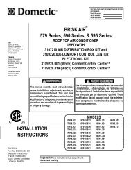
Refrigerant Flow<br />
FLANGE LOOP<br />
EVAPORATOR<br />
INLET<br />
HIGH SIDE<br />
DRIER<br />
CONDENSER<br />
COMPRESSOR DISCHARGE LINE<br />
22, 23, 26 cu. ft. Side by Side<br />
Refrigerant Flow Diagram<br />
SUCTION LINE<br />
CAPILLARY TUBE<br />
EVAPORATOR OUTLET<br />
EVAPORATOR<br />
PROCESS TUBE<br />
COMPRESSOR<br />
PROCESS TUBE<br />
©2005 Maytag <strong>Service</strong>s 16025628 19
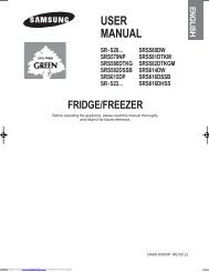
Cabinet Air Flow<br />
FREEZER BACK<br />
(AIR BAFFLE)<br />
EVAPORATOR<br />
FAN ASSEMBLY<br />
LARGE BEVERAGE CHILLER<br />
AIR SUPPLY<br />
(SOME MODELS)<br />
EVAPORATOR<br />
SMALL BEVERAGE CHILLER<br />
AIR SUPPLY<br />
(SOME MODELS)<br />
COMPRESSOR<br />
DELI<br />
AIR SUPPLY<br />
SIDE BY SIDE<br />
AIRFLOW DIAGRAM<br />
22, 23, 26 cu. ft. Side by Side<br />
Cabinet Air Flow Diagram<br />
REFRIGERATOR AIR<br />
SUPPLY TUNNEL<br />
TO FRESH FOOD<br />
COMPARTMENT CONTROLS<br />
CONDENSER<br />
AIR SUPPLY<br />
(IN FOAM)<br />
REFRIGERATOR AIR<br />
RETURN TUNNEL<br />
CONDENSER FAN<br />
ASSEMBLY<br />
20 16025628 ©2005 Maytag <strong>Service</strong>s
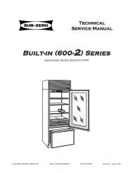
Ice and Water Dispenser Diagram<br />
ICE &WATER<br />
DISPENSER<br />
ICEMAKER<br />
5/16” x 5/16”<br />
PUSH CONNECTOR UNION<br />
WATER FILTER<br />
INLET<br />
22, 23, 26 cu. ft. Model Side by Side<br />
Ice and Water Flow Diagram<br />
DETAIL<br />
WATER FILTER<br />
OUTLET<br />
WATER<br />
TANK<br />
WATER LINE IS ROUTED IN A CONDUIT<br />
UNDER THE FLOOR OF UNIT<br />
©2005 Maytag <strong>Service</strong>s 16025628 21
Water Valve Diagram<br />
WATER TANK<br />
INLET 5/16”<br />
ICE MAKER<br />
INLET 1/4”<br />
SOLENOID<br />
VALVE<br />
DETAIL<br />
22, 23, 26 cu. ft. Model Side by Side<br />
Ice and Water Flow Diagram<br />
WATER FILTER<br />
OUTLET<br />
WATER SUPPLY<br />
HOOKUP<br />
WATER FILTER<br />
INLET<br />
22 16025628 ©2005 Maytag <strong>Service</strong>s
Typical External Sweat Pattern<br />
3<br />
3<br />
Classification of condensation:<br />
1 = Haze or Fog<br />
2 = Beading<br />
3 = Beads or Small Drops<br />
4 = Drops Running Together<br />
BTM<br />
©2005 Maytag <strong>Service</strong>s 16025628 23<br />
1
Troubleshooting Chart<br />
! WARNING<br />
To avoid risk of electrical shock, personal injury, or death, disconnect electrical power source to unit, unless test<br />
procedures require power to be connected. Discharge capacitor through a resistor before attempting to service.<br />
Ensure all ground wires are connected before certifying unit as repaired and/or operational.<br />
Troubleshooting chart on following pages contains symptoms that may be seen in malfunctioning units. Each<br />
symptom is accompanied by one or more possible causes and by a possible remedy or test to determine if<br />
components are working properly.<br />
Symptom Possible Causes Corrective Action<br />
Unit does not run<br />
No power to unit Check for power at outlet. Check<br />
fuse box/circuit breaker for blown<br />
fuse or tripped breaker. Replace or<br />
reset.<br />
Faulty power cord Check with test light at unit; if no<br />
circuit and current is indicated at<br />
outlet, replace or repair.<br />
<strong>Refrigerator</strong> section too warm<br />
Low voltage Check input voltage for proper<br />
voltage. Take appropriate action to<br />
correct voltage supply problem.<br />
Faulty motor or freezer temperature<br />
control<br />
Check all connections are tight and<br />
secure.<br />
Jumper across terminals of control. If<br />
unit runs, replace control.<br />
Faulty timer Check with test light. Replace if<br />
necessary.<br />
Faulty relay Check relay. Replace if necessary.<br />
Faulty compressor Check compressor motor windings<br />
for opens/shorts.<br />
Perform compressor direct wiring<br />
test.<br />
Replace if necessary.<br />
Faulty overload Check overload for continuity.<br />
NOTE: Ensure<br />
compressor/overload are below<br />
trip temperature before testing.<br />
Replace if necessary.<br />
Excessive door opening Consumer education<br />
Overloading of shelves Consumer education<br />
Warm or hot foods placed in cabinet Consumer education<br />
Cold control set too warm Set control to colder setting.<br />
Poor door seal Level cabinet. Adjust hinges.<br />
Replace gasket.<br />
<strong>Refrigerator</strong> airflow Check damper is opening by<br />
removing grille. With door open,<br />
damper should open. Replace if<br />
faulty.<br />
Turn control knob to colder position.<br />
Interior light remains on Check switch. Replace if necessary.<br />
Faulty condenser fan or evaporator<br />
fan<br />
Check fan and wiring. Replace if<br />
necessary.<br />
Faulty compressor Replace compressor.<br />
24 16025628 ©2005 Maytag <strong>Service</strong>s
Troubleshooting Chart<br />
! WARNING<br />
To avoid risk of electrical shock, personal injury, or death, disconnect electrical power source to unit, unless test<br />
procedures require power to be connected. Discharge capacitor through a resistor before attempting to service.<br />
Ensure all ground wires are connected before certifying unit as repaired and/or operational.<br />
Symptom Possible Causes Corrective Action<br />
<strong>Refrigerator</strong> section too cold<br />
<strong>Refrigerator</strong> temperature control set Adjust refrigerator temperature<br />
too cold<br />
control.<br />
<strong>Refrigerator</strong> airflow not properly<br />
adjusted<br />
Check air flow.<br />
Freezer and refrigerator sections too Temperature controls set too warm Reset temperature controls.<br />
warm<br />
Poor door seal Level cabinet. Adjust hinges.<br />
Replace gasket.<br />
Dirty condenser or obstructed grille Check condenser and grille. Clean.<br />
Faulty control Test control. Replace if failed.<br />
Refrigerant shortage or restriction Check for leak or restriction. Repair,<br />
evacuate and recharge system.<br />
Freezer section too cold<br />
Freezer temp control set too cold Adjust freezer temperature control.<br />
Faulty control Test control. Replace if failed.<br />
Cold control capillary not properly<br />
clamped to evaporator<br />
Reposition clamp and tighten.<br />
Unit runs continuously<br />
Temperature control set too cold Adjust temperature control.<br />
Dirty condenser or obstructed grille Check condenser and grille. Clean.<br />
Poor door seal Level cabinet. Adjust hinges.<br />
Replace gasket.<br />
Interior light remains on Check switch. Replace if necessary.<br />
Faulty condenser fan or evaporator Check fan and wiring. Replace if<br />
fan<br />
necessary.<br />
Faulty control Test control. Replace if failed.<br />
Refrigerant shortage or restriction Check for leak or restriction. Repair,<br />
evacuate and recharge system.<br />
Refrigerant overcharge Check for overcharge. Evacuate and<br />
recharge system.<br />
Unit runs continuously. Temperature<br />
normal.<br />
Unit runs continuously. Temperature<br />
too cold.<br />
Noisy operation<br />
Air in system Check for low side leak. Repair,<br />
evacuate and recharge system.<br />
Ice on evaporator See “Ice on evaporator”.<br />
Faulty defrost thermostat Check thermostat. Replace if<br />
necessary.<br />
Loose flooring or floor not firm Repair floor or brace floor.<br />
Cabinet not level Level cabinet.<br />
Tubing in contact with cabinet, other<br />
tubing, or other metal<br />
Adjust tubing.<br />
Drip pan vibrating Adjust drain pan.<br />
Fan hitting another part Ensure fan properly aligned and all<br />
attaching hardware and brackets are<br />
tight and not worn. Tighten or<br />
replace.<br />
Worn fan motor bearings Check motor for loss of lubricant or<br />
worn bearings. Replace if necessary.<br />
Compressor mounting grommets<br />
worn or missing. Mounting hardware<br />
loose or missing<br />
Free or loose parts causing or<br />
allowing noise during operation<br />
Tighten hardware. Replace<br />
grommets if necessary.<br />
Inspect unit for parts that may have<br />
worked free or loose or missing<br />
screws. Repair as required.<br />
©2005 Maytag <strong>Service</strong>s 16025628 25
Troubleshooting Chart<br />
! WARNING<br />
To avoid risk of electrical shock, personal injury, or death, disconnect electrical power source to unit, unless test<br />
procedures require power to be connected. Discharge capacitor through a resistor before attempting to service.<br />
Ensure all ground wires are connected before certifying unit as repaired and/or operational.<br />
Symptom Possible Causes Corrective Action<br />
Frost or ice on evaporator<br />
Defrost thermostat faulty Check defrost thermostat. Replace if<br />
failed.<br />
Unit starts and stops frequently<br />
(cycles on and off)<br />
Evaporator fan faulty Check fan motor. Replace if failed.<br />
Defrost heater remains open Check defrost heater continuity.<br />
Replace if failed.<br />
Defrost control faulty Check control and replace if failed.<br />
Open wire or connector Check wiring and connections.<br />
Repair as necessary.<br />
Refrigerant shortage or restriction Check for leak or restriction. Repair,<br />
evacuate and recharge system.<br />
Loose wire or thermostat<br />
connections<br />
Check wiring and connections.<br />
Repair as necessary.<br />
Supply voltage out of specification Check input voltage. Correct any<br />
supply problems.<br />
Overload protector open Check overload protector for<br />
continuity. If open, replace overload.<br />
NOTE: Ensure<br />
overload/compressor are below<br />
trip temperature before testing.<br />
Faulty compressor motor capacitor<br />
(some compressors do not require<br />
motor capacitor)<br />
Check capacitor for open/short.<br />
Replace if necessary.<br />
NOTE: Discharge capacitor<br />
before testing.<br />
Faulty fan motor Check fan motor. Replace if failed.<br />
Restricted air flow Check condenser and grille for dirt.<br />
Clean.<br />
Refrigerant shortage or restriction Check for leak or restriction. Repair,<br />
evacuate and recharge system.<br />
26 16025628 ©2005 Maytag <strong>Service</strong>s
System Diagnosis<br />
CONDITION<br />
Refrigerant<br />
Overcharge<br />
Shortage of<br />
Refrigerant<br />
Partial<br />
Restriction<br />
Air in<br />
System<br />
Low Ambient<br />
Installations<br />
(High<br />
Ambients the<br />
Reverse)<br />
Additional<br />
Heat Load<br />
Inefficient<br />
Compressor<br />
SUCTION<br />
PRESSURE<br />
VARIATION<br />
FROM<br />
NORMAL<br />
HEAD<br />
PRESSURE<br />
VARIATION<br />
FROM<br />
NORMAL<br />
T1 INLET<br />
TEMPERATURE<br />
VARIATION<br />
FROM NORMAL<br />
T2 OUTLET<br />
TEMPERATURE<br />
VARIATION<br />
FROM NORMAL<br />
T3 SUCTION<br />
TEMPERATURE<br />
VARIATION<br />
FROM NORMAL<br />
WATTAGE<br />
VARIATION<br />
FROM<br />
NORMAL<br />
Increase Increase Warmer Warmer Colder Increase<br />
Decrease<br />
Decrease<br />
Decrease or<br />
Increase<br />
See Text<br />
Decrease or<br />
Increase<br />
See Text<br />
Note 2<br />
Colder Warmer Warmer Decrease<br />
Colder Warmer Warmer Decrease<br />
Near Normal Increase Warmer Warmer Warmer Increase<br />
Decrease Decrease Colder Warmer Warmer Decrease<br />
Increase Increase Warmer Warmer Warmer Increase<br />
Increase<br />
Normal or<br />
Decrease<br />
Warmer or<br />
Colder<br />
Symptoms of an Overcharge<br />
• Above normal freezer temperatures.<br />
Longer than normal or continuous run.<br />
Freezing in refrigerator, especially on forced air<br />
meatkeeper models.<br />
Higher than normal suction and head pressure.<br />
Higher than normal wattage.<br />
Evaporator inlet and outlet temperatures warmer than<br />
normal.<br />
Suction tube temperature below ambient. Always<br />
check for separated heat exchanger when suction<br />
temperature is colder than ambient.<br />
Various conditons could indicate an overcharge. For<br />
example, if the cooling coil is not defrosted at regular<br />
intervals, due to a failure of the defrost system, the<br />
refrigerant will "flood out" and cause the suction line to<br />
frost or sweat. The cause of this problem should be<br />
corrected rather than to purge refrigerant from the<br />
sytem. Running the freezer section colder than<br />
necessary (-2 to -1 F. is considered normal package<br />
temperatures) or continuous running of the compressor<br />
for a variety of reasons, or the freezer fan motor not<br />
running, may give the indication of an overcharge.<br />
Warmer Warmer Decrease<br />
Symptoms of Refrigeration Shortage<br />
Rise in food product temperature in both<br />
compartments. (See Note 1 below.)<br />
Long or continuous run time.<br />
Look for obvious traces of oil that would occur due to a<br />
leak or cracked refrigerant line.<br />
Lower than normal wattage.<br />
Compressor will be hot to touch because of the heat<br />
generated by the motor windings from long continuous<br />
running. It will not be as hot as it would be with a full<br />
charge and long run times for some other reason such<br />
as a dirty condenser.<br />
Depending on the amount of the shortage, the<br />
condenser will not be hot, but closer to room<br />
temperature. The capillary tube will be warmer than<br />
normal from a slight shortage.<br />
If the leak is on the high side of the system, both<br />
gauges will show lower than normal readings and will<br />
show progressively lower readings as this charge<br />
becomes less. The suction pressure guage will<br />
probably indicate a vacuum.<br />
If the leak is on the low side of the system the suction<br />
pressure guage will be lower than normal - probably in<br />
a vacuum - and the head pressure gauge will be<br />
higher than normal. It will probably continue to<br />
become higher because air drawn in through the leak<br />
is compressed by the compressor and accumulates in<br />
©2005 Maytag <strong>Service</strong>s 16025628 27
System Diagnosis<br />
the high side (condenser) of the system.<br />
Only partial frosting of evaporator instead of even<br />
frosting of entire coil.<br />
NOTE 1: Usually the first thing that is noticed by the<br />
user is a rise in temperature foods. Although<br />
temperatures will rise in both the freezer section<br />
and the food compartment, the frozen meats<br />
and vegetables will not thaw immediately. The<br />
customer doesn't associate the problem with<br />
the freezer section and will first notice that milk<br />
and other food beverages are not cold enough.<br />
Under some circumstances, such as in the case of<br />
forced air meatkeeper model with a slight shortage of<br />
refrigerant, freezing in the food compartment may be<br />
experienced due to the additional running time. With a<br />
refrigerant leak, however, it always gets worse and as<br />
the refrigerant charge decreases the temperature will<br />
continue to rise.<br />
With a shortage of refrigerant the capillary line will not<br />
have a full column of liquid. As a result, there is a<br />
noticeable hissing sound in the evaporator. This should<br />
not be mistaken for the regular refrigerant boiling<br />
sounds that would be considered normal.<br />
To diagnose for a restriction versus a refrigerant<br />
shortage, discharge the system, replace the drier-filter,<br />
evacuate and recharge with the specified refrigerant<br />
charge. If the unit performs normally three possibilities<br />
exist: 1) refrigerant loss, 2) partially restricted drierfilter,<br />
and 3) moisture in system.<br />
If the unit performs as it previously did you may have a<br />
restricted capillary line or condenser or kinked line.<br />
Find the point of restriction and correct it.<br />
A restriction reduces the flow rate of the refrigerant and<br />
consequently reduces the rate of heat removal.<br />
Complete restriction may be caused by moisture, solid<br />
contaminants in the system, or a poorly soldered joint.<br />
Moisture freezes at the evaporator inlet end of the<br />
capillary tube or solid contaminants collect in the drierfilter.<br />
The wattage drops because the compressor is not<br />
circulating the usual amount of refrigerant.<br />
As far as pressure readings are concerned, if the<br />
restriction, such as a kinked line or a joint soldered shut<br />
is anywhere on the low side, the suction pressure would<br />
probably be in a vacuum while the head pressure will be<br />
near normal. If the restriction is on the high side, the<br />
suction pressure, again, will probably be in a vacuum<br />
while the head pressure will be higher than normal<br />
during the pump out period described earlier. In either<br />
case, it will take longer than the normal ten minutes or<br />
so for the head pressure to equalize with the low side<br />
after the compressor stops.<br />
Symptoms of a Restriction<br />
Always remember refrigeration (cooling) occurs on the<br />
low pressure side of a partial restriction (obviously a<br />
total restriction will completely stop the circulation of<br />
refrigerant and no cooling will take place).<br />
Physically feel the refrigeration lines when a restriction<br />
is suspected. The most common place for a restriction<br />
is at the drier-filter or at the capillary tube inlet or outlet.<br />
If the restriction is not total there will be a temperature<br />
difference at the point of restriction, the area on the<br />
evaporator side will be cooler. In many cases frost and/<br />
or condensation will be present. A longer time is<br />
required for the system to equalize.<br />
Symptoms of Air in System<br />
This can result from a low side leak or improper<br />
servicing. If a leak should occur on the low side, the<br />
temperature control would not be satisfied; thus,<br />
continuous running of the compressor would result. The<br />
compressor would eventually pump the low side into a<br />
vacuum drawing air and moisture into the system. Air<br />
and R134A do not mix so the air pressure would be<br />
added to the normal head pressure, resulting in higher<br />
than normal head pressures.<br />
Any kinked line will cause a restriction so the entire<br />
system should be visually checked.<br />
One way to determine if air is in the system is to read<br />
the head pressure gauge with the product off and<br />
A slight restriction will give the same indications as a evaporator and condenser at the same temperature and<br />
refrigerant shortage with lower than normal back<br />
then take the temperature on the condenser outlet tube.<br />
pressure, head pressure, and wattage, warmer product This temperature should be within 3° or 4° F. of what the<br />
temperatures.<br />
Pressure-Temperature Relation chart shows for the<br />
NOTE 2: If a total restriction is on the discharge side of<br />
the compressor, higher than normal head<br />
pressures and wattages would result. This is<br />
true only while the low side is being pumped out<br />
and if the restriction was between the<br />
compressor and the first half of the condenser.<br />
given idle head pressure. If the temperature of the<br />
condenser outlet is considerably lower than the idle<br />
head pressure of the gauge this would indicate there is<br />
air in the system.<br />
Thorough leak checking is necessary. Correct the<br />
source of the leak. Do not attempt to purge off the air<br />
because this could result in the system being<br />
undercharged. It is best to discharge, replace drier,<br />
evacuate and recharge with the specified refrigerant<br />
charge.<br />
28 16025628 ©2005 Maytag <strong>Service</strong>s
System Diagnosis<br />
Symptoms of Low or High Ambient<br />
Temperature Installation<br />
Lower ambient air temperature reduces the condensing<br />
temperature and therefore reduces the temperature of<br />
the liquid entering the evaporator. The increase in<br />
refrigeration effect due to operation in a lower ambient<br />
results in a decrease in power consumption and run<br />
time. At lower ambients there is a reduction in cabinet<br />
heat leak which is partially responsibile for lower power<br />
consumption and run time.<br />
An increase in refrigeration effect cannot be expected<br />
below a certain minimum ambient temperature. This<br />
temperature varies with the type and design of the<br />
product.<br />
Generally speaking, ambient temperatures cannot be<br />
lower than 60° F. without affecting operating efficiency.<br />
Conversely, the higher the ambient temperature the<br />
higher the head pressure must be to raise the high side<br />
refrigerant temperature above that of the condensing<br />
medium. Therefore, head pressure will be higher as the<br />
ambient temperature raises. <strong>Refrigerator</strong>s installed in<br />
ambient temperatures lower than 60° F. will not perform<br />
as well because the pressures within the system are<br />
generally reduced and unbalanced. This means that the<br />
lower head pressure forces less liquid refrigerant<br />
through the capillary line. The result is the symptoms of<br />
a refrigerant shortage. The lower the ambient<br />
temperature the more pronounced this condition<br />
becomes.<br />
When a point where the ambient temperature is below<br />
the cut-in of the Temperature Control is reached, the<br />
compressor won't run.<br />
The drain traps will freeze in ambient temperatures of<br />
32° F.<br />
Heat Load<br />
A greater heat load can result from the addition of more<br />
than normal supply of foods, such as after doing the<br />
weekly shopping. Other items contributing to an<br />
additional heat load would be excessive door openings,<br />
poor door sealing, interior light remaining on, etc.<br />
An increase in heat being absorbed by the refrigerant in<br />
the evaporator will affect the temperature and pressure<br />
of the gas returning to the compressor. Compartment<br />
temperatures, power consumption, discharge, and<br />
suction pressures are all affected by heat load.<br />
Pressures will be higher than normal under heavy heat<br />
load.<br />
©2005 Maytag <strong>Service</strong>s 16025628 29
Disassembly Procedures<br />
! WARNING<br />
To avoid risk of electrical shock, personal injury, or death, disconnect electrical power source to unit, unless test<br />
procedures require power to be connected. Discharge capacitor through a resistor before attempting to service.<br />
Ensure all ground wires are connected before certifying unit as repaired and/or operational.<br />
<strong>Refrigerator</strong> Compartment<br />
Light Switch<br />
Use a taped putty knife to carefully pry light switch out<br />
of liner. When light switch is free of compartment<br />
liner, remove wires from light switch. Remove light<br />
switch from unit.<br />
Cold Control, Defrost Timer, Damper Control<br />
Assembly (some models)<br />
1. Remove cold control and fresh food control knobs.<br />
2. Remove screw just between knobs and on right side<br />
of control cover.<br />
3. Remove cover by pulling cover to the right and<br />
forward off tabs.<br />
4. Disconnect wiring harness from cabinet.<br />
5. Remove screws from side holding complete<br />
assembly to center bulkhead.<br />
6. Release front tab by depressing rearward on tab.<br />
7. Pull complete assembly carefully to your right and out<br />
from center bulkhead.<br />
8. Carefully pull cold control capillary out of center<br />
bulkhead sleeve.<br />
9. Reverse procedure to reassemble.<br />
DAMPER CONTROL<br />
SHAFT EXTENSION<br />
COLD CONTROL, DAMPER CONTROL, DEFROST TIMER ASSEMBLY<br />
DAMPER CONTROL GASKETS<br />
DEFROST TIMER<br />
COLD CONTROL<br />
DAMPER CONTROL<br />
Freezer Cold Control (some models)<br />
1. See disassembly instructions for removal of cold<br />
control, defrost timer, damper control assembly.<br />
2. With assembly out disconnect wires and ground to<br />
cold control.<br />
3. Carefully detach capillary tube from assembly holder.<br />
4. Depress tab at bottom of cold contol to relase control<br />
from assembly.<br />
5. Reverse procedure to reassemble.<br />
Mid Level Electronic Control (some models)<br />
1. Remove hex head screws holding control to cabinet.<br />
2. Unplug connectors from cabinet harness and remove<br />
control assembly.<br />
3. Remove cover of board by squeezing tabs on cover to<br />
release cover fom assembly to expose Electronic<br />
Control.<br />
4. Unplug wires from Electronic Control board and unclip<br />
from Control Assembly.<br />
Mid Level Electronic Control<br />
Defrost Timer (some models)<br />
1. Remove cold control and fresh food control knobs.<br />
2. Remove screw right side of control cover.<br />
3. Remove cover by pulling cover to the right and forward<br />
off liner.<br />
4. Release tabs holding defrost timer to assembly.<br />
5. Remove timer by lifting off of assembly.<br />
6. Disconnect harness from defrost timer.<br />
7. Reverse procedure to reassemble.<br />
30 16025628 ©2005 Maytag <strong>Service</strong>s
Disassembly Procedures<br />
! WARNING<br />
To avoid risk of electrical shock, personal injury, or death, disconnect electrical power source to unit, unless test<br />
procedures require power to be connected. Discharge capacitor through a resistor before attempting to service.<br />
Ensure all ground wires are connected before certifying unit as repaired and/or operational.<br />
Adaptive Defrost Control (ADC) (some models)<br />
1. Remove cold control and fresh food control knobs.<br />
2. Remove screw just between knobs and on right side<br />
of control cover.<br />
3. Remove cover by pulling cover to the right and forward<br />
off liner.<br />
4. Release front left tab to remove ADC cover.<br />
5. Remove ADC board from locating tabs.<br />
6. Disconnect harness from ADC board.<br />
7. Reverse procedure to reassemble.<br />
ADC CONTROL HOUSING<br />
ADC HOUSING<br />
ADC BOARD<br />
ADC COVER<br />
Water Filter Assembly (some models)<br />
1. Remove filter cover opening cover and pulling rear left<br />
side of cover to the left to release cover from holding<br />
pin.<br />
2. Filter head can be released from holding bracket by<br />
opening tabs on left side filter head and pulling<br />
downward and to your left to release filter head.<br />
3. Tubing needs to be disconnected from water valves<br />
in the machine compartment. (see water valve<br />
removal)<br />
4. After tubing is loose from water valves pull the filter<br />
head and tubing out the front of unit.<br />
5. Reverse procedure to reassemble.<br />
NOTE: Make sure to note tubing end colors when<br />
reinstalling new head and tubing assembly.<br />
Water Tank Assembly (some models)<br />
Damper Control (some models)<br />
1. Remove cold control and fresh food control knobs.<br />
2. Remove screw just between knobs and on right side<br />
of control cover.<br />
3. Remove cover by pulling cover to the right and<br />
forward off tabs.<br />
4. Slide off styrafoam block. Retain for future use.<br />
5. Pull shaft extension free of control.<br />
1. Remove crisper drawers from fresh food compartment.<br />
2. Remove hex screw holding water tank to rear<br />
bulkhead.<br />
3. On rear of cabinent remove hex screws holding water<br />
valve cover plate.<br />
4. Remove plate and tubing away from cabinet to expose<br />
water valves and tubing.<br />
5. Disconnect water tube from secondary valve coming<br />
from water tank, remove compression nut from tubing.<br />
6. On front of unit remove toe grill and disconnect water<br />
coupler going to water dispenser<br />
7. Remove compression nut from water tubing on cabinet<br />
side of connection.<br />
8. From rear of cabinet pull water tube out of conduit<br />
NOTE: Observe wide and narrow clip leg orientation of going to dispenser.<br />
shaft and damper cover.<br />
9. From inside of fresh food compartment pull tubing up<br />
6. Release side tabs holding damper control to<br />
assembly.<br />
and out of cabinet to complete removal of water tank.<br />
10. Reverse procedure to reassemble.<br />
7. Lift damper control off of assembly<br />
Crisper Light Cover and Socket<br />
NOTE: Retain damper gasket for future use.<br />
8. Reverse procedure to reassemble.<br />
1. Push down and forward on light cover and lift off tabs.<br />
2. Remove light bulb and pry socket with taped putty<br />
knife to release socket from liner.<br />
Electronically Controled Damper<br />
3. Disconnect wires from socket.<br />
1. Remove damper cover by removing hex head screw<br />
and lifting off of damper.<br />
4. Reverse procedure to reassemble.<br />
2. Remove foam insert by pulling it off of damper control.<br />
3. Depress two clips that hold front of damper in place to<br />
release damper from assembly, lift damper out.<br />
4. Disconnect wires from damper and remove damper.<br />
5. Reverse procedure to reassemble.<br />
Fresh Food Thermistor<br />
1. Remove damper cover by removing hex head screw to<br />
expose thermistor.<br />
2. Unclip thermistor from assembly.<br />
3. Cut wires at thermistor to remove.<br />
Freezer Compartment<br />
Freezer Light socket<br />
1. Remove auger ice bucket.<br />
2. Remove auger motor assembly. (see auger motor<br />
assembly removal.<br />
3. Remove light bulbs.<br />
4. Disconnect wiring from light sockets.<br />
5. Squeeze retaining tab to release sockets<br />
6. Reverse procedure to reassemble.<br />
©2005 Maytag <strong>Service</strong>s 16025628 31
Disassembly Procedures<br />
! WARNING<br />
To avoid risk of electrical shock, personal injury, or death, disconnect electrical power source to unit, unless test<br />
procedures require power to be connected. Discharge capacitor through a resistor before attempting to service.<br />
Ensure all ground wires are connected before certifying unit as repaired and/or operational.<br />
Auger Motor Assembly (some models)<br />
1. Remove auger ice bucket and fast freeze shelf.<br />
2. Remove light bulbs<br />
3. Remove two hex head screws, one from each side of<br />
cover.<br />
4. Lift and slide assembly toward the front, disconnect<br />
wiring harness and remove assembly.<br />
Auger Motor (some models)<br />
1. Remove auger drive hex nut.<br />
2. Remove three hex nuts holding auger motor to<br />
assembly.<br />
3. Disconnect wires from auger motor capacitor.<br />
4. Reverse procedure to reassemble.<br />
Auger Motor Capacitor (some models)<br />
1. Remove auger ice bucket and fast freeze shelf.<br />
2. Remove auger motor assembly. (see auger motor<br />
assembly removal.<br />
3. Disconnect leads from capacitor, remove hex screw<br />
and remove capacitor.<br />
4. Reverse procedure to reassemble.<br />
Evaporator Fan Motor Assembly<br />
1. Remove all freezer shelving.<br />
2. Remove lower evaporator cover hex head screws.<br />
3. Remove evaporator cover.<br />
4. Disconnect evaporator fan wiring and ground from<br />
motor.<br />
5. Raise top freezer cover about two inches.<br />
6. Grasp and pull complete evaporator motor assembly<br />
toward you.<br />
7. Remove assembly from freezer.<br />
S HROUD A SSEMBLY<br />
E VAPORATOR F AN<br />
M OTOR<br />
E VAPORATOR F AN<br />
C LIP<br />
F AN B LADE<br />
Evaporator Fan Motor and Fan Blade<br />
1. Remove evaporator fan motor assembly (see<br />
evaporator fan motor assembly removal).<br />
2. Remove evaporator fan blade by pulling blade off<br />
evaporator fan shaft.<br />
3. Remove fan motor by squeezing motor retainer clips<br />
together to release retainer.<br />
4. Remove retainer and slide motor out.<br />
5. Reverse procedure to reassemble. Evaporator fan<br />
blade should be pushed down on on shaft until it is<br />
seated.<br />
Freezer Thermistor<br />
1. Remove Icemaker bucket.<br />
2. Remove Icemaker by removing hex head screws and<br />
unplugging icemaker harness.<br />
3. Remove upper freezer shelves to access freezer back.<br />
4. Remove freezer back hex head screws.<br />
5. Rotate back to expose freezer thermistor.<br />
6. Cut wire at thermistor and remove thermistor.<br />
Evaporator Removal<br />
NOTE: Reclaim refrigerant per instructions in “<strong>Service</strong><br />
Procedures” before attempting evaporator<br />
removal. To avoid system contamination, do not<br />
leave system open for more than 10 minutes.<br />
1. Remove all freezer shelving.<br />
2. Remove lower evaporator cover hex head screws.<br />
3. Remove evaporator cover.<br />
4. Remove defrost thermostat and defrost heater from<br />
coil ( see disassembly instructions for both).<br />
5. Release evaporator coil from clips by pulling coil off of<br />
clips.<br />
6. Unsweat evaporator coil after completing reclaiming<br />
procedures found in <strong>Service</strong> Procedures section of this<br />
manual.<br />
7. Reverse procedure to reassemble.<br />
32 16025628 ©2005 Maytag <strong>Service</strong>s
Disassembly Procedures<br />
! WARNING<br />
To avoid risk of electrical shock, personal injury, or death, disconnect electrical power source to unit, unless test<br />
procedures require power to be connected. Discharge capacitor through a resistor before attempting to service.<br />
Ensure all ground wires are connected before certifying unit as repaired and/or operational.<br />
Defrost Terminator (Thermostat)<br />
1. Remove all freezer shelving.<br />
2. Remove lower evaporator cover hex head screws.<br />
3. Remove evaporator cover.<br />
4. Disconnect orange lead from defrost heater.<br />
5. Cut Brown lead close to defrost terminator.<br />
6. Unclip defrost terminator from evaporator coil.<br />
7. Replace terminator and use wire nut(s) included in<br />
defrost terminator kit.<br />
8. Reverse procedure to reassemble.<br />
HEATER CLIPS<br />
DEFROST THERMOSTAT<br />
DEFROST HEATER<br />
Defrost Heater<br />
1. Remove all freezer shelving..<br />
2. Remove lower evaporator cover hex head screws..<br />
3. Remove evaporator cover.<br />
4. Grasp evaporator by left side to release coil from<br />
retainer clips.<br />
5. Turn Evaporator slightly to expose heater leads.<br />
6. Disconnect heater leads from harness.<br />
7. Release heater clips holding heater to evaporator coil.<br />
8. Remove heater.<br />
9. Reverse procedure to reassemble.<br />
Ice Maker Removal (some models)<br />
1. Remove auger ice bucket.<br />
2. Disconnect ice maker harness from rear bulkhead.<br />
3. Remove front two screws from left ice bucket rail.<br />
4. Remove screws supporting ice maker from side<br />
bulkhead.<br />
5. Remove ice maker.<br />
6. Reverse procedure to reassemble.<br />
NOTE: Make sure to get fill tube inserted in to fill cup<br />
fully when reassembling<br />
Machine Compartment<br />
Water Valve (some models)<br />
1. Remove water valve cover plate on left side of<br />
machine compartment.<br />
2. Disconnect wiring from water valve, reference color of<br />
connector to correct solenoid.<br />
3. Disconnect water tubing from water valve, reference or<br />
mark tubing to ensure correct hookup upon<br />
reassemble.<br />
4. Remove hex screw attaching valve to water valve cover<br />
plate.<br />
5. Reverse procedure to reassemble.<br />
FROM WATER FILTER<br />
(BLUE LINE)<br />
TO WATER TANK<br />
TO ICE MAKER<br />
TO WATER FILTER<br />
(YELLOW LINE)<br />
©2005 Maytag <strong>Service</strong>s 16025628<br />
Condenser Fan Motor and Blade<br />
1. Remove machine compartment hex screws.<br />
2. Remove cover<br />
3. Disconnect wiring harness connector from condenser<br />
motor.<br />
4. Remove hex screws from mounting brackets<br />
attached to motor.<br />
5. Remove motor and fan blade out the rear of shroud.<br />
6. Remove the retainer nut to remove fan blade.<br />
7. Reverse procedure to reassemble.<br />
Compressor<br />
1. Remove machine compartment hex screws.<br />
2. Remove cover.<br />
3. Remove bale strap which retains overload/relay/<br />
capacitor.<br />
4. Pull overload/relay/capacitor assembly off of<br />
compressor terminals.<br />
5. Disconnect ground wires attached to compressor.<br />
33
Disassembly Procedures<br />
! WARNING<br />
To avoid risk of electrical shock, personal injury, or death, disconnect electrical power source to unit, unless test<br />
procedures require power to be connected. Discharge capacitor through a resistor before attempting to service.<br />
Ensure all ground wires are connected before certifying unit as repaired and/or operational.<br />
6. Follow reclaiming procedures in <strong>Service</strong> Procedures<br />
section of this manual.<br />
7. Remove drier.<br />
8. Unbraze low and high pressure lines at compressor.<br />
9. Remove compressor mounting bolts.<br />
10.Lift compressor out of unit.<br />
NOTE: Install new drier and compressor per instructions<br />
in “<strong>Service</strong> Procedures.” Evacuate and recharge<br />
sealed system per instructions in “<strong>Service</strong><br />
Procedures.”<br />
Condensate Drain Tube<br />
1. Remove machine compartment hex screws.<br />
2. Remove cover.<br />
3. Locate and remove hex screw holding drain tube in<br />
place.<br />
4 Remove drain tube by pulling down on drain tube.<br />
5. Reverse procedure to reassemble<br />
Condensate Drain Pan<br />
NOTE: Condensate drip pan may spill when steps 1<br />
thru 4 are performed. Have a towel ready to mop<br />
up spillage.<br />
1. Remove machine compartment and water valve cover<br />
hex screws.<br />
2. Remove covers<br />
3. Remove screws holding condenser shroud to base<br />
pan.<br />
4. Raise rear of unit up about three inches and block up.<br />
5. Remove two rear torx head screws holding rear of<br />
basepan to cabinet located under basepan.<br />
6. Lower cabinet back to floor after removing blocks.<br />
7. Raise cabinet off of basepan enough to allow removal<br />
of condenser shroud, disconnect any wiring attached<br />
to shroud to ease removal of shroud.<br />
8. After shroud is removed bend copper tubing up out of<br />
condensate pan to allow removal of condensate pan.<br />
9. Reverse procedure to reassemble.<br />
Overload/Relay<br />
1. Remove machine compartment hex screws.<br />
2. Discharge capacitor (if unit is so equipped) through a<br />
10.000-ohm resistor.<br />
3. Using fingers and standard screwdriver, press and<br />
pry bale strap off the overload/relay/capacitor<br />
assembly.<br />
4. Reverse procedure to reassemble.<br />
Condenser Removal<br />
NOTE: Condenser is removed by laying unit on it’s back<br />
and requires at least two people to do this<br />
procedure.<br />
1. Remove machine compartment hex screws.<br />
2. Remove cover.<br />
3. Remove condenser fan motor and shroud.<br />
4. Disconnect harness plug connecting machine<br />
compartment to cabinet.<br />
5. Follow reclaiming procedures in <strong>Service</strong> Procedures<br />
section of this manual.<br />
6. Remove drier and unbraze tubing connecting<br />
machine compartment to cabinet.<br />
7. Disconnect all cabinet wiring from machine tray.<br />
8. With the help of second person lay unit on back on<br />
raised surface.<br />
9. Remove four torx head screws holding basepan to<br />
cabinet.<br />
10.Lift and remove basepan to access condenser coil.<br />
11. Unbraze condenser coil from connecting tubing.<br />
12. Remove condenser coil by unsnapping it from<br />
retainers in basepan.<br />
13. Reverse procedure to reassemble.<br />
Bottom of Cabinet<br />
Front Leveling Rollers<br />
1. Remove toe grill and hinge caps.<br />
2. Raise and block unit up three inches off of floor.<br />
3. Screw front leveler bolts until they are loose from<br />
leveling roller.<br />
4. Slide leveling roller out rear of slot to remove roller.<br />
5. Reverse procedure to reassemble.<br />
Rear Leveling Rollers<br />
1. Remove machine compartment and water valve<br />
cover hex screws.<br />
2. Remove covers.<br />
3. Tilt unit forward lifting rear of unit up about three<br />
inches.<br />
4. Block unit up to keep weight off of rear leveling rollers.<br />
5. Un screw leveling bolts from rear leveling rollers.<br />
6. Push the leveling roller out the slots in the bottom of<br />
the unit.<br />
7. Reverse procedure to reassemble.<br />
34 16025628 ©2005 Maytag <strong>Service</strong>s
Disassembly Procedures<br />
! WARNING<br />
To avoid risk of electrical shock, personal injury, or death, disconnect electrical power source to unit, unless test<br />
procedures require power to be connected. Discharge capacitor through a resistor before attempting to service.<br />
Ensure all ground wires are connected before certifying unit as repaired and/or operational.<br />
Cabinet Doors<br />
Door Gaskets<br />
1. Grasp gasket in upper corners and pull gasket out of<br />
dart retainer.<br />
2. When reinstalling door gaskets start at corners<br />
pushing dart edge into retainer and make sure to<br />
seat gasket flush to door.<br />
Dispenser Facade (some models)<br />
1. Remove drip tray by pulling it straight out from door.<br />
2. Remove two hex screws at the bottom of facade that<br />
were hidden by drip tray.<br />
3. Push down on facade to release retainer clips.<br />
4. Remove facade and disconnect ten pin connector from<br />
control board.<br />
5. Reverse procedure to reassemble.<br />
Dispenser Ice Chute Door (some models)<br />
1. Remove dispenser facade (see dispenser facade<br />
removal)<br />
2. Remove ice chute assembly (see D/C solenoid<br />
removal)<br />
3. After ice chute assembly is removed unsnap ice<br />
chute dispenser door from assembly.<br />
4. Retain spring if good, replace if bad.<br />
5. Remove rubber seal from door and replace if bad.<br />
6. Reverse procedure to reassemble.<br />
ICE CHUTE<br />
ASSEMBLY<br />
ICE CHUTE<br />
ICE CHUTE DOOR<br />
DOOR<br />
HINGE<br />
LIGHT SOCKET<br />
DC SOLENOID<br />
Dispenser Light Socket (some models)<br />
1. Remove dispenser facade (see dispenser facade<br />
removal)<br />
2. Remove light bulb.<br />
3. Disconnect wires to socket assembly.<br />
4. Squeeze tabs located by terminals to release socket.<br />
5. Reverse procedure to reassemble.<br />
Dispenser D/C Solenoid (some models)<br />
1. Remove dispenser facade (see dispenser facade<br />
removal)<br />
2. Remove dispenser water tube clip.<br />
3. Remove water tube from assembly collar.<br />
4. Remove wires from dispenser light socket.<br />
5. Disconnect ground wire from solenoid assembly.<br />
6. Disconnect wires from D/C solenoid.<br />
7. Remove screws holding D/C solenoid and ice chute<br />
assembly.<br />
8. Remove complete assembly.<br />
9. Rotate to backside and remove screws holding D/C<br />
solenoid to ice chute assembly.<br />
10.Lift ice chute door to release plunger from retainer.<br />
11. Slide D/C solenoid out of the side of ice chute<br />
assembly.<br />
12. Reverse procedure to reassemble.<br />
Dispenser Water Tube (some models)<br />
1. Remove toe grill and left hinge cap to expose<br />
dispenser water line coupler.<br />
2. Disconnect water line coupler.<br />
3. Remove compression nut and sleeve from door side<br />
of coupler.<br />
4. Remove dispenser facade (see dispenser facade<br />
removal).<br />
5. Pull water tube up from conduit in cavity to remove<br />
water tube.<br />
6. Reverse procedure to reassemble.<br />
©2005 Maytag <strong>Service</strong>s 16025628 35
Ice ‘N Water Systems<br />
Troubleshooting of 5 button electronic Ice ‘N Water dispenser<br />
Dispenser Operation<br />
Select WATER, CRUSHED or CUBED mode by pushing the button on the dispenser panel. A green indicator light<br />
above the button indicates the current selection. Selection mode cannot be changed from CRUSHED to CUBED or<br />
from CUBED to CRUSHED while ice dispenser is in operation.<br />
Dispenser Light<br />
Light activates at full power when dispensing ice or water. A sensor activates light at half-power when light level<br />
around refrigerator is low. Activate or deactivate sensor by pushing AUTO LIGHT button located on control façade.<br />
Green light above AUTO LIGHT button indicates sensor is active.<br />
Dispenser Lock<br />
Prevents operation of water and ice dispensers. To activate or deactivate lock, press and hold DISPENSER LOCK<br />
button for 3 seconds. Green light above button indicates dispenser lock.<br />
Automatic Lock Out<br />
Shuts down both ice and water mechanisms of dispenser when either mechanism has run continuously for 5<br />
minutes. To return power to dispenser, press and hold DISPENSER LOCK for 3 seconds. Auger motor shuts off<br />
automatically after 3 minutes of continuous operation. After about 3 minutes in shut-off state, auger motor<br />
resets automatically.<br />
Filter Status Light<br />
This feature reminds users to replace water filter after 1 year have passed or after 500 gallons of water are<br />
filtered, whichever happens first.<br />
NOTE: Filter status light turns red after 1 year have passed or after 500 gallons of water are dispensed, even if<br />
bypass is installed and unit is used without filter cartridge.<br />
Green light indicates filter in good condition. Red light indicates filter replacement needed.<br />
The filter monitor works by keeping track of time:<br />
• Six months is approximately 16 million seconds.<br />
• The refrigerator’s water system requires about 53,000 seconds to pass 500 gallons of water.<br />
• Each second that water is dispensed counts as 1.20 ounces of water.<br />
• An additional 3.20 ounces of water is counted every 30 minutes. This attempts to account for ice usage.<br />
Filter Status Light Reset<br />
Once filter light turns red, it remains red until reset. To reset filter indicator, press both DISPENSER LOCK and WATER<br />
pushbuttons simultaneously and hold for 4 seconds. Make sure green light flashes 3 times when indicator<br />
resets.<br />
36 16025628 ©2005 Maytag <strong>Service</strong>s
Ice ‘N Water Systems<br />
Table A: Harness 10-pin Connector Configuration<br />
Pin Color Signal<br />
1 GY Ice Door Chute Solenoid<br />
2 BR Dispenser Light<br />
3 BU Crushed<br />
4 OR Cubed<br />
5 BK Line Out<br />
6 RD Main Actuator<br />
7 YL Water Valve<br />
8 VT Line In<br />
9<br />
10 WH Neutral<br />
Note: All voltage measurements are referenced to line neutral or pin 10 (WH wire) of 10-pin connector.<br />
Symptom Possible Cause Test Procedure Repair<br />
No LED lit<br />
Switch failure in With unit powered, open freezer door. Press freezer door Replace<br />
freezer door.<br />
switch in. If freezer light does not turn off, switch is defective. switch.<br />
Incorrect harness Verify wire color on 10-pin connector. Refer to Table A. Correct<br />
wiring.<br />
wiring.<br />
No power to the PCB. With unit powered, measure voltage between (WH wire) and Replace PCB<br />
(VT wire) pin 8 of 10-pin connector. Meter should read<br />
if meter reads<br />
120VAC.<br />
120VAC.<br />
No dispenser light No continuity.<br />
Disconnect power. Measure continuity between (BR wire) pin Repair open<br />
when Main or<br />
Water dispenser<br />
2 of 10-pin connector and dispenser lamp terminal.<br />
connection.<br />
switch is pressed Failed light bulb or With unit powered, press the Main dispenser switch.<br />
Replace<br />
in Water, Crushed PCB.<br />
Measure voltage on pin 2 (BR wire) of 10-pin connector. dispenser<br />
or Cubed mode.<br />
Voltage should read 120 VAC.<br />
light bulb if<br />
voltage reads<br />
120 VAC.<br />
Dispenser light is Failed Main dispenser Disconnect power. Remove both leads from the switch and Replace<br />
on without<br />
switch (failed short) measure resistance across switch terminals. Resistance switch<br />
pressing the Main<br />
should read less than 1 Ω in this position and higher than 10<br />
or Water dispenser<br />
MΩ when switch is open.<br />
switch in Water,<br />
Crushed or Cubed<br />
mode.<br />
Failed PCB<br />
With PCB powered, measure voltage on pin 3 (BU wire) of 10pin<br />
connector. Voltage should read 0 VAC.<br />
Replace PCB.<br />
Water LED is Failed Main dispenser Disconnect power. Remove both leads from the switch and Replace<br />
illuminated but switch (failed open) measure resistance across switch terminals. Resistance switch.<br />
does not dispense<br />
should read less than 1 Ω in this position and higher than 10<br />
water when Main<br />
MΩ when switch is open.<br />
dispenser switch is<br />
pressed.<br />
No continuity<br />
Disconnect power. Remove the cover of freezer door hinge<br />
located on top of the unit and disconnect the connectors.<br />
Check OR wire (pin 4 of 10-pin connector) for continuity.<br />
Repair open<br />
connection.<br />
Water starts to Failed Main dispenser Disconnect power. Remove both leads from the switch and Replace<br />
dispense as soon switch (failed short) measure resistance across switch terminals. Resistance switch.<br />
as Water mode is<br />
should read less than 1 Ω in this position and higher than 10<br />
selected without<br />
MΩ when switch is open.<br />
pressing the Main<br />
dispenser switch<br />
Failed PCB<br />
With PCB powered, measure voltage on pin 7 (YL wire) of 10pin<br />
connector. Voltage should read 0 VAC.<br />
Replace PCB.<br />
©2005 Maytag <strong>Service</strong>s 16025628 37
Ice ‘N Water Systems<br />
Symptom Possible<br />
Cause<br />
Cubed LED is illuminated Failed Main<br />
but does not dispense dispenser<br />
cubed ice when Main switch (failed<br />
dispenser switch is<br />
pressed.<br />
open)<br />
No continuity<br />
Cubed ice starts to<br />
dispense as soon as<br />
Cubed mode is selected<br />
without pressing the Main<br />
dispenser switch<br />
Dispenser operates<br />
continuously even when<br />
Dispenser Lock mode is<br />
activated.<br />
Auto Light mode does not<br />
operate.<br />
Ice or Water dispenser<br />
mechanism runs<br />
continuously.<br />
Filter Status LED never<br />
changes to red.<br />
1. Auger motor operates in<br />
Cubed or Crushed mode<br />
but ice door chute never<br />
opens.<br />
2. Auger motor operates in<br />
Cubed or Crushed mode<br />
but ice door chute never<br />
closes.<br />
No LED lit, Water<br />
dispenser operates, auger<br />
motor operates only in<br />
Cubed mode and ice chute<br />
door does not open or<br />
remains open.<br />
No LED lit, Water<br />
dispenser operates, auger<br />
motor operates only in<br />
Cubed mode and dispenser<br />
light is on continuously.<br />
Neither Water, Crushed or<br />
Cubed LED will not<br />
illuminate but Water,<br />
Crushed or Cubed mode<br />
operates properly when<br />
selected.<br />
Failed auger<br />
motor or PCB.<br />
Failed Main<br />
dispenser<br />
switch (failed<br />
short)<br />
Failed PCB<br />
Test Procedure Repair<br />
Disconnect power. Remove both leads from the<br />
switch and measure resistance across switch<br />
terminals. Resistance should read less than 1 Ω in<br />
this position and higher than 10 MΩ when switch<br />
is open.<br />
Disconnect power. Remove the cover of freezer<br />
door hinge located on top of the unit and<br />
disconnect the connectors. Check OR wire (pin 4<br />
of 10-pin connector) for continuity.<br />
With PCB powered, press the Main dispenser<br />
switch. Measure voltage on pin 4 (OR wire) of 10-<br />
pin connector. Voltage should read 120VAC.<br />
Disconnect power. Remove both leads from the<br />
switch and measure resistance across switch<br />
terminals. Resistance should read higher than 10<br />
MΩ when switch is open and less than 1 Ω when<br />
switch is closed.<br />
With PCB powered, measure voltage on pin 4<br />
(OR wire) of 10-pin connector. Voltage should<br />
read 0 VAC.<br />
Failed PCB With PCB powered, measure voltage on pin 5 (BK<br />
wire) of 10-pin connector. Voltage should read 0<br />
VAC.<br />
Failed PCB With PCB powered and Auto Light activated,<br />
cover the light sensor. Measure voltage on pin 2<br />
(BR wire) of 10-pin connector. Voltage should<br />
read 1/2 the AC power supply (120 VAC).<br />
Failed PCB With PCB powered, measure voltage on pin 5 (BK<br />
wire) of 10-pin connector. Voltage should read 0<br />
VAC.<br />
Failed PCB Verify with the user if unit has been unplugged for<br />
a long period.<br />
Demonstrate reset operation to customer.<br />
Failed solenoid Disconnect power. Remove both leads from the<br />
solenoid and measure the resistance across<br />
solenoid terminals. Resistance should read<br />
101.2 ± 10%.<br />
Failed PCB Measure voltage on pin 1 (GY wire) of 10-pin<br />
connector. Voltage should read approximately<br />
55VDC when ice chute door is open (solenoid<br />
energized) or 0VDC when closed (solenoid not<br />
energized).<br />
Failed PCB<br />
Failed PCB<br />
Replace switch.<br />
Repair open<br />
connection.<br />
Replace auger motor if<br />
voltage reads 120VAC.<br />
If not, replace PCB.<br />
Replace switch<br />
Replace PCB.<br />
Replace PCB<br />
Replace PCB.<br />
Replace PCB.<br />
Replace water filter and<br />
reset Filter Status.<br />
Replace PCB if problem<br />
continues. Customer<br />
education.<br />
Replace solenoid.<br />
Replace PCB.<br />
Replace PCB<br />
Replace PCB<br />
Failed PCB Replace PCB<br />
38 16025628 ©2005 Maytag <strong>Service</strong>s
Ice ‘N Water Systems<br />
Symptom Possible<br />
Cause<br />
Crushed LED is illuminated Failed Main<br />
but does not dispense dispenser<br />
crushed ice when Main switch (failed<br />
dispenser switch is<br />
pressed.<br />
open)<br />
No continuity<br />
Crushed ice starts to<br />
dispense as soon as<br />
Crushed mode is selected<br />
without pressing the Main<br />
dispenser switch.<br />
Failed auger<br />
motor or PCB.<br />
Failed Main<br />
dispenser<br />
switch (failed<br />
short)<br />
Failed PCB<br />
Seconds to dispense 10 oz. water<br />
Supply pressure 35 psig 45 psig 55 psig 75 psig<br />
Filter model<br />
Bypass installed<br />
Filter model<br />
New filter installed<br />
Test Procedure Repair<br />
Disconnect power. Remove both leads from the<br />
switch and measure resistance across switch<br />
terminals. Resistance should read less than 1 Ω in<br />
this position and higher than 10 MΩ when switch<br />
is open.<br />
Disconnect power. Remove the cover of freezer<br />
door hinge located on top of the unit and<br />
disconnect the connectors. Check BU wire (pin 3<br />
of 10-pin connector) for continuity.<br />
With PCB powered, press the Main dispenser<br />
switch. Measure voltage on pin 3 (BU wire) of 10-<br />
pin connector. Voltage should read 120VAC.<br />
Disconnect power. Remove both leads from the<br />
switch and measure resistance across switch<br />
terminals. Resistance should read less than 1 Ω in<br />
this position and higher than 10 MΩ when switch<br />
is open.<br />
With PCB powered, measure voltage on pin 3 (BU<br />
wire) of 10-pin connector. Voltage should read 0<br />
VAC.<br />
9.0 8.0 7.0 6.0<br />
11.0 10.0 8.0 7.0<br />
Replace switch.<br />
Repair open<br />
connection.<br />
Replace auger motor if<br />
voltage reads 120VAC.<br />
If not, replace PCB.<br />
Replace switch<br />
Replace PCB.<br />
<strong>Amana</strong> specifies a minimum supply pressure of 35 psig for water filter units. Minimum pressure<br />
requirement ensures that water valves close and sufficient water volume is available to fill icemaker.<br />
Proper fill is 140 cc. of water in 7.5 seconds. Failure of water valves to close because of low pressure<br />
will result in fill-tube freeze-up or dripping at cavity.<br />
©2005 Maytag <strong>Service</strong>s 16025628 39
Ice ‘N Water Systems<br />
Troubleshooting of 3 button electronic Ice ‘N Water dispenser<br />
Dispenser Operation<br />
Select WATER, CRUSHED or CUBED mode by pushing the button on the dispenser panel. A green<br />
indicator light above the button indicates the current selection.<br />
Dispenser Light<br />
Light activates at full power when dispensing ice or water.<br />
Table A: Harness 9-pin Connector Configuration<br />
Pin Color Signal<br />
1 GY Ice Door Chute<br />
Solenoid<br />
2 BR Dispenser Light<br />
3 OR Cubed<br />
4 BU Crushed<br />
5 RD Line<br />
6 YL Main Actuator<br />
7 VT Line In<br />
8<br />
9 WH Neutral<br />
Note: All voltage measurements are referenced to line neutral or pin 9 (WH wire) of 9-pin<br />
connector<br />
40 16025628 ©2005 Maytag <strong>Service</strong>s
Ice ‘N Water Systems<br />
Symptom Possible<br />
Cause<br />
No LED lit Switch failure in<br />
freezer door.<br />
No dispenser<br />
light when<br />
dispenser switch<br />
is pressed in<br />
Water, Crushed<br />
or Cubed mode.<br />
Dispenser light is<br />
on without<br />
pressing the<br />
dispenser switch<br />
in Water,<br />
Crushed or<br />
Cubed mode.<br />
Water LED is<br />
illuminated but<br />
does not<br />
dispense water<br />
when dispenser<br />
switch is pressed<br />
Water starts to<br />
dispense as soon<br />
as Water mode is<br />
selected without<br />
pressing the<br />
dispenser switch<br />
Crushed LED is<br />
illuminated but<br />
does not<br />
dispense crushed<br />
ice when<br />
dispenser switch<br />
is pressed.<br />
Incorrect<br />
harness wiring.<br />
No power to<br />
the PCB.<br />
No continuity.<br />
Failed light bulb<br />
or PCB.<br />
Failed<br />
dispenser<br />
switch (failed<br />
short)<br />
Failed PCB<br />
Failed<br />
dispenser<br />
switch (failed<br />
open)<br />
Test Procedure Repair<br />
With unit powered, open freezer door. Press<br />
freezer door switch in. If freezer light does not<br />
turn off, switch is defective.<br />
Verify wire color on 9-pin connector. Refer to<br />
Table A.<br />
With unit powered, measure voltage between pin<br />
9 (WH wire) and pin 7 (VT wire) of 9-pin<br />
connector. Meter should read 120VAC.<br />
Disconnect power. Measure continuity between<br />
pin 2 (BR wire) of 9-pin connector and dispenser<br />
lamp terminal.<br />
With unit powered, press the dispenser switch.<br />
Measure voltage on pin 2 (BR wire) of 9-pin<br />
connector. Voltage should read 120VAC.<br />
Disconnect power. Remove both leads from the<br />
switch and measure resistance across switch<br />
terminals. Resistance should read less than 1 Ω<br />
in this position and higher than 10 MΩ when<br />
switch is open.<br />
With unit powered, measure voltage on pin 2<br />
(BR wire) of 9-pin connector. Voltage should<br />
read 0VAC<br />
Disconnect power. Remove both leads from the<br />
switch and measure resistance across switch<br />
terminals. Resistance should read less than 1 Ω<br />
in this position and higher than 10 MΩ when<br />
switch is open.<br />
No continuity Disconnect power. Remove the cover of freezer<br />
door hinge located on top of the unit and<br />
disconnect the connectors. Check YL wire (pin 6<br />
Failed water<br />
valve or PCB.<br />
Failed<br />
dispenser<br />
switch (failed<br />
short)<br />
Failed PCB<br />
Failed<br />
dispenser<br />
switch (failed<br />
open)<br />
No continuity<br />
Failed auger<br />
motor or PCB.<br />
of 9-pin connector) for continuity.<br />
With PCB powered, press dispenser switch.<br />
Measure voltage on pin 6 (YL wire) of 9-pin<br />
connector. Voltage should read 120VAC.<br />
Disconnect power. Remove both leads from the<br />
switch and measure resistance across switch<br />
terminals. Resistance should read less than 1 Ω<br />
in this position and higher than 10 MΩ when<br />
switch is open.<br />
With PCB powered, measure voltage on pin 6<br />
(YL wire) of 9-pin connector. Voltage should<br />
read 0 VAC.<br />
Disconnect power. Remove both leads from the<br />
switch and measure resistance across switch<br />
terminals. Resistance should read less than 1 Ω<br />
in this position and higher than 10 MΩ when<br />
switch is open.<br />
Disconnect power. Remove the cover of freezer<br />
door hinge located on top of the unit and<br />
disconnect the connectors. Check BU wire (pin 4<br />
of 9-pin connector) for continuity.<br />
With PCB powered, press dispenser switch.<br />
Measure voltage on pin 4 (BU wire) of 9-pin<br />
connector. Voltage should read 120VAC.<br />
Replace switch.<br />
Correct wiring.<br />
Replace PCB if meter<br />
reads 120VAC.<br />
Repair open connection.<br />
Replace dispenser light<br />
bulb. If not, replace PCB.<br />
Replace switch.<br />
Replace PCB.<br />
Replace switch.<br />
Repair open connection.<br />
Replace water valve if<br />
voltage reads 120VAC. If<br />
not, replace PCB.<br />
Replace switch.<br />
Replace PCB.<br />
Replace switch.<br />
Repair open connection.<br />
Replace auger motor if<br />
voltage reads 120VAC. If<br />
not, replace PCB.<br />
©2005 Maytag <strong>Service</strong>s 16025628 41
Ice ‘N Water Systems<br />
Symptom Possible<br />
Cause<br />
Crushed ice Failed<br />
starts to dispense dispenser<br />
as soon as switch (failed<br />
Crushed mode is<br />
selected without<br />
short)<br />
pressing the<br />
dispenser switch.<br />
Failed PCB<br />
Cubed LED is<br />
illuminated but<br />
does not<br />
dispense cubed<br />
ice when<br />
dispenser switch<br />
is pressed.<br />
Cubed ice starts<br />
to dispense as<br />
soon as Cubed<br />
mode is selected<br />
without pressing<br />
the dispenser<br />
switch<br />
1. Auger motor<br />
operates in<br />
Cubed or<br />
Crushed mode<br />
but ice chute door<br />
never opens.<br />
2. Auger motor<br />
operates in<br />
Cubed or<br />
Crushed mode<br />
but ice chute door<br />
never closes.<br />
No LED lit, auger<br />
motor operates<br />
only in Cubed<br />
mode, and ice<br />
chute door never<br />
opens or never<br />
closes.<br />
No LED lit, auger<br />
motor operates<br />
only in Cubed<br />
mode, and<br />
dispenser light<br />
never switches on<br />
or never switches<br />
off.<br />
Neither Water,<br />
Crushed or<br />
Cubed LED will<br />
not illuminate but<br />
Water, Crushed<br />
or Cubed mode<br />
operates properly<br />
when selected.<br />
Failed<br />
dispenser<br />
switch (failed<br />
open)<br />
No continuity<br />
Failed auger<br />
motor or PCB.<br />
Failed<br />
dispenser<br />
switch (failed<br />
short)<br />
Failed PCB<br />
Test Procedure Repair<br />
Disconnect power. Remove both leads from the<br />
switch and measure resistance across switch<br />
terminals. Resistance should read less than 1 Ω<br />
in this position and higher than 10 MΩ when<br />
switch is open.<br />
With PCB powered, measure voltage on pin 4<br />
(BU wire) of 9-pin connector. Voltage should<br />
read 0 VAC.<br />
Disconnect power. Remove both leads from the<br />
switch and measure resistance across switch<br />
terminals. Resistance should read less than 1 Ω<br />
in this position and higher than 10 MΩ when<br />
switch is open.<br />
Disconnect power. Remove the cover of freezer<br />
door hinge located on top of the unit and<br />
disconnect the connectors. Check OR wire (pin 3<br />
of 9-pin connector) for continuity.<br />
With PCB powered, press the dispenser switch.<br />
Measure voltage on pin 3 (OR wire) of 9-pin<br />
connector. Voltage should read 120VAC.<br />
Disconnect power. Remove both leads from the<br />
switch and measure resistance across switch<br />
terminals. Resistance should read higher than 10<br />
MΩ when switch is open and less than 1 Ω when<br />
switch is closed.<br />
With PCB powered, measure voltage on pin 3<br />
(OR wire) of 9-pin connector. Voltage should<br />
read 0 VAC.<br />
Failed solenoid Disconnect power. Remove both leads from the<br />
solenoid and measure the resistance across<br />
solenoid terminals. Resistance should read –<br />
101.2 ohms ±10%<br />
Failed PCB Measure voltage on pin 1 (GY wire) of 9-pin<br />
connector. Voltage should read approximately<br />
55VDC when ice chute door is open (solenoid<br />
energized) or 0 VDC when closed (solenoid not<br />
energized).<br />
Failed PCB<br />
Failed PCB<br />
Replace switch<br />
Replace PCB.<br />
Replace switch.<br />
Repair open connection.<br />
Replace auger motor if<br />
voltage reads 120VAC. If<br />
not, replace PCB.<br />
Replace switch<br />
Replace PCB.<br />
Replace solenoid.<br />
Replace PCB.<br />
Replace PCB<br />
Replace PCB<br />
Failed PCB Replace PCB<br />
42 16025628 ©2005 Maytag <strong>Service</strong>s
Appendix A<br />
A - 1
R<br />
Table of Contents<br />
Important Safety Instructions ..... 1-2<br />
Installation ...................................... 3-9<br />
Temperature Controls............... 10-12<br />
Fresh Food Features ................. 13-15<br />
Freezer Features .............................. 16<br />
Ice and Water............................. 17-19<br />
Side-by-Side<br />
Use & Care Guide<br />
Water Filter................................. 20-22<br />
Food Storage Tips..................... 23-25<br />
Care and Cleaning.................... 26-29<br />
Operating Sounds ........................... 30<br />
Troubleshooting......................... 31-34<br />
Warranty & <strong>Service</strong> ......................... 35<br />
Form No. C/11/04 Part No. 12842107 www.maytag.com Litho U.S.A.
1<br />
Important Safety Instructions<br />
Installer: Please leave this guide with this appliance.<br />
Consumer: Please read and keep this Use & Care<br />
Guide for future reference. This guide provides<br />
proper use and maintenance information.<br />
Keep sales receipt and/or cancelled check as proof<br />
of purchase.<br />
Call: 1-800-688-9900 U.S.A.<br />
1-800-688-2002 Canada<br />
Have complete model and serial number<br />
identification of your refrigerator. This is located on a<br />
data plate inside the refrigerator compartment, on<br />
the upper left side. Record these numbers below for<br />
easy access.<br />
Model Number _______________________________<br />
Revision Number ______________________________<br />
Serial Number ________________________________<br />
Date of Purchase______________________________<br />
In our continuing effort to improve the quality and<br />
performance of our appliances, it may be necessary<br />
to make changes to the appliance without revising<br />
this guide.<br />
What You Need to Know About<br />
Safety Instructions<br />
Warning and Important Safety Instructions appearing in<br />
this guide are not meant to cover all possible<br />
conditions and situations that may occur. Common<br />
sense, caution and care must be exercised when<br />
installing, maintaining or operating appliance.<br />
Always contact the manufacturer about problems or<br />
conditions you do not understand.<br />
Recognize Safety Symbols, Words,<br />
Labels<br />
DANGER<br />
DANGER – Immediate hazards which WILL result<br />
in severe personal injury or death.<br />
WARNING<br />
WARNING – Hazards or unsafe practices which<br />
COULD result in severe personal injury or death.<br />
CAUTION<br />
CAUTION – Hazards or unsafe practices which COULD<br />
result in minor personal injury or property damage.<br />
DANGER<br />
To reduce risk of injury or death, follow basic<br />
precautions, including the following:<br />
IMPORTANT: Child entrapment and suffocation<br />
are not problems of the past. Junked or abandoned<br />
refrigerators are still dangerous – even if they sit out<br />
for “just a few days.” If you are getting rid of your old<br />
refrigerator, please follow the instructions below to<br />
help prevent accidents.<br />
Before you throw away your old<br />
refrigerator or freezer:<br />
•Take off the doors.<br />
•Leave the shelves in place so<br />
children may not easily climb<br />
inside.<br />
This appliance is equipped with a three-prong<br />
grounding plug for your protection against possible<br />
electrical shock hazards. It must be plugged into a<br />
grounding receptacle. Where a standard two-prong<br />
wall receptacle is encountered, it is the personal<br />
responsibility and obligation of the customer to have it<br />
replaced with a properly grounded three-prong wall<br />
receptacle. Do not under any circumstances, cut or<br />
remove the third (ground) prong from the power cord.<br />
Do not use an adapter plug.<br />
Power supply cord with<br />
three-prong grounding plug<br />
Grounding type<br />
wall receptacle
Important Safety Instructions<br />
To reduce risk of fire, electric shock, serious injury or<br />
death when using your refrigerator, follow these basic<br />
precautions, including the following:<br />
1. Read all instructions before using the refrigerator.<br />
2. Observe all local codes and ordinances.<br />
3. Be sure to follow grounding instructions.<br />
4. Check with a qualified electrician if you are not<br />
sure this appliance is properly grounded.<br />
5. Do not ground to a gas line.<br />
6. Do not ground to a cold-water pipe.<br />
7. <strong>Refrigerator</strong> is designed to operate on a separate<br />
115 volt, 15 amp., 60 cycle line.<br />
8. Do not modify plug on power cord. If plug does<br />
not fit electrical outlet, have proper outlet installed<br />
by a qualified electrician.<br />
9. Do not use a two-prong adapter, extension cord<br />
or power strip.<br />
10. Do not remove warning tag from power cord.<br />
11. Do not tamper with refrigerator controls.<br />
12. Do not service or replace any part of refrigerator<br />
unless specifically recommended in Use & Care<br />
Guide or published user-repair instructions. Do<br />
not attempt service if instructions are not understood<br />
or if they are beyond personal skill level.<br />
WARNING<br />
SAVE THESE INSTRUCTIONS<br />
13. Always disconnect refrigerator from electrical<br />
supply before attempting any service. Disconnect<br />
power cord by grasping the plug, not the cord.<br />
14. Install refrigerator according to Installation<br />
Instructions. All connections for water, electrical<br />
power and grounding must comply with local<br />
codes and be made by licensed personnel when<br />
required.<br />
15. Keep your refrigerator in good condition. Bumping<br />
or dropping refrigerator can damage refrigerator<br />
or cause refrigerator to malfunction or leak. If<br />
damage occurs, have refrigerator checked by<br />
qualified service technician.<br />
16. Replace worn power cords and/or loose plugs.<br />
17. Always read and follow manufacturer’s storage<br />
and ideal environment instructions for items being<br />
stored in refrigerator.<br />
18. Your refrigerator should not be operated in the<br />
presence of explosive fumes.<br />
19. Children should not climb, hang or stand on any<br />
part of the refrigerator.<br />
20. Clean up spills or water leakage associated with<br />
water installation.<br />
2
3<br />
Location<br />
Installation<br />
• Do not install refrigerator near oven, radiator or other<br />
heat source. If not possible, shield refrigerator with<br />
cabinet material.<br />
• Do not install where temperature falls below 55° F<br />
(13° C) or rises above 110° F (43° C). Malfunction<br />
may occur at this temperature.<br />
• <strong>Refrigerator</strong> is designed for indoor household<br />
application only.<br />
Measuring the Opening<br />
When installing your refrigerator, allow 1 ⁄2" space at top<br />
and 1 ⁄2" space behind machine compartment cover<br />
(located in the rear) for proper air circulation. If the<br />
refrigerator is placed with the door hinge side against<br />
a wall, you may want to allow additional space so the<br />
door can be opened wider.<br />
Subflooring or floor coverings (i.e. carpet, tile, wood<br />
floors, rugs) may make your opening smaller than<br />
anticipated.<br />
Some clearance may be gained by using the leveling<br />
procedure under Leveling.<br />
IMPORTANT: If refrigerator is to be installed into a<br />
recess where the top of the refrigerator is completely<br />
covered, use dimensions from floor to top of hinge cap<br />
to verify proper clearance.<br />
Transporting Your <strong>Refrigerator</strong><br />
• NEVER transport refrigerator on its side. If an<br />
upright position is not possible, lay refrigerator on its<br />
back. Allow refrigerator to sit upright for<br />
approximately 30 minutes before plugging it in to<br />
assure oil returns to the compressor. Plugging<br />
refrigerator in immediately may cause damage to<br />
internal parts.<br />
• Use an appliance dolly when moving refrigerator.<br />
ALWAYS truck refrigerator from its side or<br />
back–NEVER from its front.<br />
•Protect outside finish of refrigerator during transport<br />
by wrapping cabinet in blankets or inserting padding<br />
between the refrigerator and dolly.<br />
• Secure refrigerator to dolly firmly with straps or<br />
bungee cords. Thread straps through handles when<br />
possible. Do not overtighten. Overtightening<br />
restraints may dent or damage outside finish.<br />
Door and Hinge Removal<br />
Some installations require door removal to get<br />
refrigerator to final location.<br />
WARNING<br />
To avoid severe personal injury or death, observe the<br />
following:<br />
• Disconnect power to refrigerator before removing<br />
doors. Connect power only after replacing doors.<br />
•Green ground wire must be attached to top hinge<br />
while performing door removal and replacement.<br />
•Tape decorative panels (select models) securely<br />
into place before removing door handles.<br />
CAUTION<br />
To avoid property damage, observe the following:<br />
•Protect vinyl or other flooring with cardboard, rugs<br />
or other protective material, prior to moving<br />
refrigerator.<br />
• Do not adjust refrigerator to be any shorter than<br />
681 ⁄2" tall (minus hinge and cap). Doing so may<br />
damage underside components.<br />
1. Unplug power cord from power source.<br />
2. Remove toe grille and bottom bracket covers (see<br />
page 9).<br />
• Open both doors 180°, or as wide as possible.<br />
For ice and water dispensing models only:<br />
Remove the left side bracket cover by carefully<br />
pulling the water line to pry the cover loose. Then<br />
continue to maintain downward pressure to the<br />
notched side of the cover while swinging it off<br />
(see page 9).
Note<br />
Installation<br />
•For refrigerators in operation, shut off water before<br />
removing water line from the door.<br />
To Disconnect the Water Line:<br />
•Push in white collar (A) and hold.<br />
•Pull the door-side tube from the connector (B).<br />
To Reconnect the Water Line:<br />
• Firmly push tube 5 ⁄8" into the connector. Use<br />
lines on the tube as a guide for full insertion.<br />
• If tube end is damaged, cut off 5 ⁄8" before<br />
reconnecting.<br />
• If leaking occurs, reconnect the line.<br />
3. Close doors.<br />
4. Remove top hinge covers by<br />
removing Phillips screws.<br />
5. Unscrew 5 ⁄16" hex head screws from<br />
top hinges.<br />
For water dispensing<br />
models only:<br />
• Do not remove screw<br />
connecting green ground<br />
wire.<br />
B<br />
A<br />
6. For ice and water dispensing models only:<br />
Detach main wire connector harness and red wire<br />
harness.<br />
•To detach main wire<br />
harness, use a flat blade<br />
tool or fingernail to press<br />
junction point between two<br />
connectors to release.<br />
•To detach red wire harness,<br />
press tab on underside of<br />
connector to release.<br />
7. Remove top hinges along with doors.<br />
8. Remove bottom hinges with a 3 ⁄8" hex head driver.<br />
Replacing the Doors<br />
•To replace the doors, follow the steps in Door and<br />
Hinge Removal in reverse order.<br />
IMPORTANT: If water line tube end is damaged, cut<br />
off 5 ⁄8" before reconnecting.<br />
4
5<br />
Installation<br />
Connecting the Water Supply<br />
(select models)<br />
WARNING<br />
To reduce the risk of injury or death, follow<br />
basic precautions, including the following:<br />
• Read all instructions before installing ice maker.<br />
•Do not attempt installation if instructions are not<br />
understood or if they are beyond personal skill<br />
level.<br />
• Observe all local codes and ordinances.<br />
• Do not service ice maker unless specifically<br />
recommended in Use & Care Guide or published<br />
user-repair instructions.<br />
• Disconnect power to refrigerator before installing<br />
ice maker.<br />
•Water damage due to an improper water<br />
connection may cause mold/mildew growth. Clean<br />
up spills or leakage immediately!<br />
CAUTION<br />
To avoid property damage or possible injury,<br />
follow basic precautions, including the<br />
following:<br />
• Consult a plumber to connect 1 ⁄4" O.D. copper<br />
tubing to household plumbing to assure<br />
compliance with local codes and ordinances.<br />
• Confirm water pressure to water valve is between<br />
35 and 100 pounds per square inch, 20 pounds<br />
per square inch without filter.<br />
• Do not use a self-piercing, or 3 ⁄16" saddle valve.<br />
Both reduce water flow can become clogged over<br />
time, and may cause leaks if repair is attempted.<br />
•Tighten nuts by hand to prevent cross threading.<br />
Finish tightening nuts with pliers and wrenches.<br />
Do not overtighten.<br />
•Wait two to three hours before placing refrigerator<br />
into final position to check and correct any water<br />
leaks. Recheck for leaks after 24 hours.<br />
•Verify the copper tubing under the sleeve is<br />
smooth and free from defects. Do not reuse an old<br />
sleeve.<br />
Materials Needed<br />
• 1 ⁄4" outer diameter flexible copper tubing<br />
• Shut-off valve (requires a 1 ⁄4" hole to be drilled into<br />
water supply line before valve attachment)<br />
• Adjustable wrench<br />
• 1 ⁄4" hex nut driver<br />
Note<br />
•Add 8' to tubing length needed to reach water<br />
supply for creation of service loop.<br />
1. Create service loop with copper<br />
tubing (minimum 2' diameter).<br />
Avoid kinks in the copper tubing<br />
when bending the service loop.<br />
2. Remove plastic cap from water valve<br />
inlet port.<br />
3. Place brass nut (A) and<br />
sleeve (B) on copper<br />
tube end as illustrated.<br />
(Do not use old sleeve.)<br />
4. Place end of copper tubing into water<br />
valve inlet port. Shape tubing slightly. Do<br />
not kink – so that tubing feeds straight<br />
into inlet port.<br />
5. Slide brass nut over sleeve and screw nut<br />
into inlet port. Tighten nut with wrench.<br />
IMPORTANT: Do not overtighten. Cross<br />
threading may occur.<br />
6. Pull on tubing to confirm connection is<br />
secure. Connect tubing to frame with<br />
water tubing clamp (C) and turn on<br />
water supply. Check for leaks and<br />
correct if necessary. Continue to C<br />
observe the water supply connection<br />
for two to three hours prior to moving<br />
the refrigerator to its permanent<br />
location.<br />
7. Monitor water connection for 24 hours.<br />
Correct leaks, if necessary.<br />
A<br />
2' diameter<br />
minimum<br />
B
Installation<br />
Handle Installation<br />
If not installed, the handle is located in the interior of the<br />
fresh food section or attached to the back of your refrigerator.<br />
Remove and discard handle packaging and tape.<br />
Handle design varies from refrigerator to refrigerator.<br />
Please reference the appropriate instructions for your<br />
model.<br />
Front Mount Handle with Extensions<br />
Materials Needed<br />
• Gloves to protect hands<br />
• Phillips screwdriver<br />
• Plastic door handle removal card (or 1 ⁄32" thick plastic<br />
card), retain the card<br />
Attach Extensions to Handle:<br />
1. Align handle and<br />
extension as shown.<br />
2. Place extension in<br />
handle opening.<br />
3. Apply slight pressure<br />
to both sides of the extension piece.<br />
4. Slide extension until it stops on inside edge of<br />
handle.<br />
To Install:<br />
1. The handles are to be oriented<br />
as shown.<br />
2. Align front mount door handle<br />
clip with the door tabs.<br />
3. Ensure the handle clips are<br />
positioned slightly above the<br />
door tabs.<br />
Handle<br />
Clip<br />
Door<br />
Tab<br />
4. Rotate the handle so that the<br />
handle is flat against the door.<br />
5. Push the handle down against the upper<br />
door tab just enough to allow it to hang<br />
unsupported.<br />
6. Align bottom of handle with lower door<br />
tab. Press upper handle end to door<br />
surface and firmly grasp lower end of<br />
handle. Gently slide handle upward until<br />
bottom of handle settles on door surface,<br />
then reverse direction, sliding downward<br />
to almost engaging tab with clip.<br />
7. Grasp the handle firmly and slide down<br />
until it clicks. The audible click indicates<br />
fastening clips are securely interlocked.<br />
To Remove:<br />
1. Flex the handle away from the door panel.<br />
Simultaneously place door handle removal<br />
card underneath the base of the lower<br />
handle. Insert the card to the line or until<br />
it stops.<br />
2. Grasp the lower part of the handle firmly<br />
and lift to remove.<br />
6
7<br />
Installation<br />
Wide-by-Side Handles<br />
To Install:<br />
1. Align fresh food handle with trim<br />
retainer and door clip.<br />
2. Make sure the tabs of the handle clip<br />
are below the tabs of the door clip.<br />
3. Rotate the handle so that the handle is<br />
flat against the door (see page 6).<br />
4. The tab on the lower part of the handle<br />
will align with the hole in the handle<br />
cap.<br />
5. Slide handle upward until it clicks.<br />
6. Snap top of handle into trim retainer<br />
clip.<br />
7. Repeat for freezer handle.<br />
To Remove:<br />
1. Protect the area above the handle<br />
trim with tape. Insert the tip of a flat blade<br />
screwdriver between the handle trim and door<br />
panel. Carefully pry the trim away from the door<br />
panel.<br />
2. Pull trim free from the trim retainer.<br />
3. Insert door removal card (or 1 ⁄32" thick plastic card))<br />
between the handle and door panel (approximately<br />
11 ⁄2").<br />
4. Grasp the handle firmly and pull downward to<br />
remove.<br />
5. Repeat for freezer handle.<br />
Full-Length Aluminum Handles<br />
To Install:<br />
1. Release top door trim by removing<br />
Phillips screws from top of fresh food<br />
door and retain screws for later use.<br />
2. Align notches on back of handle with<br />
retaining clips on doors. Insert clips<br />
into notches and slide handle<br />
down until it contacts bottom<br />
trim.<br />
3. Replace top door trim and<br />
Phillips screws.<br />
4. Repeat instructions 1-3 to install<br />
other handle.<br />
WARNING<br />
To avoid possible injury and damage to property,<br />
tape decorative panels (select models) securely into<br />
place before removing door handles.<br />
To Remove:<br />
1. Release top door trim by removing<br />
Phillips screws from top of fresh food<br />
door and retain screws for later use.<br />
2. Grasp handle firmly with both hands.<br />
Slide handle upward<br />
approximately 3 ⁄4" to release.<br />
3. Repeat instructions 1-2 to<br />
remove other handle.<br />
To Reinstall:<br />
1. Repeat in reverse order.<br />
Door Clip
Installation<br />
Installing Front-Mounted Handles for<br />
Stainless Steel<br />
1. Loosen lower door clip on door with<br />
a phillips screwdriver.<br />
2. Locate predrilled hole at base of<br />
handle, and fit hollow end of<br />
handle over lower door clip.<br />
3. Fit other end of handle over upper<br />
door clip and slide up as far as<br />
possible.<br />
NOTE: If top of handle does not<br />
fit over top clip, loosen lower clip<br />
further until fit can be<br />
accomplished.<br />
4. Insert phillips screwdriver into<br />
predrilled hole at base of handle<br />
to tighten screw. Insert plastic<br />
button plug into hole, as<br />
illustrated.<br />
5. Repeat above steps to install<br />
other handle.<br />
Removing Front-Mounted Handles for<br />
Stainless Steel<br />
1. Remove plastic button plug at<br />
base of handle with a very small<br />
flat-blade screwdriver.<br />
• Insert phillips screwdriver into<br />
predrilled hole to remove<br />
screw.<br />
2. Slide handle down and remove<br />
from door clip.<br />
3. Repeat above steps to remove<br />
other handle.<br />
8
9<br />
Leveling<br />
Installation<br />
CAUTION<br />
To protect personal property and refrigerator from<br />
damage, observe the following:<br />
•Protect vinyl or other flooring with cardboard, rugs,<br />
or other protective material.<br />
• Do not use power tools when performing leveling<br />
procedure.<br />
To enhance the appearance and maintain performance,<br />
the refrigerator should be level.<br />
Note<br />
• Complete any required door reversal, panel<br />
installation and/or a water supply connection,<br />
before leveling.<br />
Materials Needed<br />
• 3 ⁄8" hex head driver<br />
• Carpenter’s level<br />
1. Remove toe grille.<br />
• Grasp firmly and pull bottom<br />
outward to unclip.<br />
2. Remove bottom bracket cover(s).<br />
• Place the eraser end of a pencil or similar blunt<br />
tool in the cover notch.<br />
A B<br />
Notch<br />
Location<br />
• Use slight pressure to pry the<br />
cover loose.<br />
• Continue to maintain<br />
downward pressure to the<br />
notched side of the cover while<br />
swinging it off.<br />
3. Using hex head driver, turn both of the front<br />
adjustment screws (A) clockwise to raise and<br />
counterclockwise to lower the front of the<br />
refrigerator.<br />
B A<br />
4. Turn both rear adjustment screws (B) clockwise to<br />
raise and counterclockwise to lower the rear of the<br />
refrigerator.<br />
A B<br />
B A<br />
5. Using the carpenter’s level, make sure front of<br />
refrigerator is 1 ⁄4" (6 mm) or 1 ⁄2 bubble higher than<br />
back of refrigerator and that the refrigerator is level<br />
from side to side.<br />
6. If required, correct rocking of refrigerator by<br />
turning rear adjustment screw clockwise to raise<br />
rocking corner. If doors are uneven, do the<br />
following:<br />
• Determine which<br />
door needs to be<br />
raised.<br />
•Turn front roller<br />
adjustment screw (A)<br />
clockwise to raise<br />
front corner of door.<br />
•If one refrigerator door has reached the limit of<br />
its adjustment range and doors are still not level,<br />
raise or lower the opposite door by turning roller<br />
adjustment screw counterclockwise.<br />
• Check with level to verify 1 ⁄4" tilt to the back for<br />
proper door closure.<br />
• If refrigerator is aligned and stable, replace toe<br />
grille and hinge covers.<br />
7. Replace bracket cover(s).<br />
•Position cover into the outer edge of the hinge.<br />
•Swing the cover toward the cabinet and snap it<br />
into place.<br />
8. Replace the toe grille.<br />
Note<br />
•For proper reinstallation, ensure the “top” marking<br />
on the interior of the toe grille is oriented correctly.<br />
• Align the toe grille mounting clips with the lower<br />
cabinet slots.<br />
•Push the toe grille firmly until it snaps into place.
Temperature Controls<br />
Dial Temperature Controls<br />
(select models)<br />
The controls are located at the back left of the<br />
refrigerator compartment.<br />
Note<br />
•The freezer control turns the cooling system on.<br />
Neither section will cool if freezer control is set to<br />
OFF.<br />
Initial Control Settings<br />
After plugging the refrigerator in,<br />
set the controls.<br />
•To adjust the controls, turn the<br />
control knob to the left or right<br />
as desired.<br />
• Set the freezer control on 4.<br />
• Set the refrigerator control on 4.<br />
•Let the refrigerator run at least 8<br />
to 12 hours before adding food.<br />
Warm Cabinet Surfaces<br />
At times, the front of the refrigerator cabinet may be<br />
warm to the touch. This is a normal occurrence that<br />
helps prevent moisture from condensing on the<br />
cabinet. This condition will be more noticeable when<br />
you first start the refrigerator, during hot weather and<br />
after excessive or lengthy door openings.<br />
Adjusting the Controls<br />
• 24 hours after adding food, you may decide that one<br />
or both compartments should be colder or warmer. If<br />
so, adjust the control(s) as indicated in the<br />
Temperature Control Guide table below. See page 23<br />
for instructions on checking compartment<br />
temperature.<br />
• Except when starting the refrigerator, do not change<br />
either control more than one number at a time.<br />
• Allow 24 hours for temperatures to stabilize.<br />
• Changing either control will have some effect on the<br />
temperature of the other compartment.<br />
Temperature Control Guide<br />
<strong>Refrigerator</strong> too warm Turn the refrigerator control<br />
to next higher number.<br />
<strong>Refrigerator</strong> too cold Turn the refrigerator control<br />
to next lower number.<br />
Freezer too warm Turn the freezer control to<br />
next higher number.<br />
Freezer too cold Turn the freezer control to<br />
next lower number.<br />
Turn refrigerator OFF Turn the freezer control to<br />
OFF.<br />
Note<br />
•Turning freezer control to OFF stops cooling in<br />
both compartments. It does not shut off power to<br />
the refrigerator.<br />
Touch Temperature Controls<br />
(select models, style varies by model)<br />
The controls are located at the top front of the<br />
refrigerator compartment.<br />
Control<br />
Initial Control Settings<br />
After plugging the refrigerator in, set the controls.<br />
•Pressing the or pads adjusts the controls to<br />
the desired setting.<br />
• Set the freezer control on 4.<br />
• Set the refrigerator control on 4.<br />
•Let the refrigerator run at least 8 to 12 hours before<br />
adding food.<br />
Warm Cabinet Surfaces<br />
At times, the front of the refrigerator cabinet may be<br />
warm to the touch. This is a normal occurrence that<br />
helps prevent moisture from condensing on the<br />
cabinet. This condition will be more noticeable when<br />
you first start the refrigerator, during hot weather and<br />
after excessive or lengthy door openings.<br />
10
11<br />
Temperature Controls<br />
Adjusting the Controls<br />
• 24 hours after adding food, you may decide that one or<br />
both compartments should be colder or warmer. If so,<br />
adjust the control(s) as indicated in the Temperature<br />
Control Guide table below.<br />
• Except when starting the refrigerator, do not change either<br />
control more than one number at a time.<br />
• Allow 24 hours for temperatures to stabilize.<br />
Temperature Control Guide<br />
<strong>Refrigerator</strong> too warm Set the refrigerator control to<br />
next higher number by<br />
pressing the pad.<br />
<strong>Refrigerator</strong> too cold Set the refrigerator control to<br />
next lower number by<br />
pressing the pad.<br />
Freezer too warm Set the freezer control to next<br />
higher number by pressing the<br />
pad.<br />
Freezer too cold Set the freezer control to next<br />
lower number by pressing the<br />
pad.<br />
Turn refrigerator OFF Press the freezer or<br />
refrigerator pad until a<br />
dash “–” appears in the<br />
display.<br />
Triple Cool Climate Control<br />
(select models)<br />
The control is located at the top front of the fresh food<br />
compartment.<br />
Control<br />
Initial Temperature Setting<br />
Temperatures are preset at the factory at 38° F (3° C) in the<br />
fresh food compartment and 0° F (-18° C) in the freezer<br />
compartment.<br />
Adjusting the Control<br />
24 hours after adding food, you may decide that one or both<br />
compartments should be colder or warmer. If so, adjust the<br />
control as indicated in the Temperature Control Guide below.<br />
• The first touch of the or pads shows the current<br />
temperature setting.<br />
• The display will show the new setting for approximately three<br />
seconds, and then return to the actual temperature currently<br />
within that compartment.<br />
• Do not change either control more than one degree at a time.<br />
Allow temperature to stabilize for 24 hours before making a<br />
new temperature adjustment.<br />
Temperature Control Guide<br />
<strong>Refrigerator</strong> too cold Set the refrigerator control to<br />
next higher number by<br />
pressing the pad.<br />
<strong>Refrigerator</strong> too warm Set the refrigerator control to<br />
next lower number by<br />
pressing the pad.<br />
Freezer too cold Set the freezer control to next<br />
higher number by pressing the<br />
pad.<br />
Freezer too warm Set the freezer control to next<br />
lower number by pressing the<br />
pad.<br />
Turn refrigerator OFF Press the freezer pad<br />
until OFF appears in the<br />
display. Press either the<br />
freezer or refrigerator pad<br />
to turn back on.<br />
Speed Ice<br />
When activated, Speed Ice reduces the freezer temperature to<br />
the optimum setting for 24 hours in order to produce more ice.<br />
Note: When the Speed Ice feature is in operation, the and<br />
pads for the freezer control will not operate.<br />
Reset Filter (select models)<br />
When a water filter has been installed in the refrigerator, the<br />
yellow Order light will illuminate when 90 percent of the volume<br />
of water for which the filter is rated has passed through the filter<br />
OR 11 months have elapsed since the filter has been installed.<br />
The red Replace light will illuminate when the rated volume of<br />
water has passed through the filter OR 12 months have elapsed<br />
since the filter was installed. A new filter should be installed<br />
immediately when the Replace light is illuminated.<br />
After replacing the filter, press and hold the Reset Filter pad for<br />
three seconds. The Order and Replace lights will go off.<br />
Vacation Mode<br />
The Vacation Mode feature causes the freezer to defrost less<br />
frequently, conserving energy. The Vacation Mode indicator light
Temperature Controls<br />
will illuminate when the feature is activated. To deactivate, press<br />
the Vacation Mode pad again OR open either door. The indicator<br />
light will go off.<br />
Notes<br />
• Door openings will not deactivate Vacation Mode for<br />
approximately one hour after activation.<br />
• If vacationing for more than a few days, see the Preparing<br />
for Vacation section, page 29.<br />
Temp Alarm<br />
The Temp Alarm system will alert you if the freezer or fresh food<br />
temperatures exceed normal operating temperatures due to a<br />
power outage or other event. When activated, the Temp Alarm light<br />
will illuminate.<br />
If the freezer or fresh food temperatures have exceeded these limits,<br />
the display will alternately show the current compartment<br />
temperatures and the highest compartment temperatures reached<br />
when the power was out. An audible alarm will sound repeatedly.<br />
Press the Temp Alarm pad once to stop the audible alarm. The<br />
Temp Alarm light will continue to flash and the temperatures will<br />
alternate until the temperatures have stabilized.<br />
To turn off Temp Alarm, press and hold the Temp Alarm pad for<br />
three seconds. The indicator light will go off.<br />
Door Alarm<br />
The Door Alarm will alert you when one of the doors has been left<br />
open for five continuous minutes. When this happens, an audible<br />
alarm will sound every few seconds until the door is closed OR the<br />
Door Alarm pad is pressed to deactivate the feature.<br />
Max Cool<br />
When activated, Max Cool causes the fresh food and freezer<br />
temperatures to drop to the minimum settings on the control. This<br />
cools down the refrigerator and freezer after extended door<br />
openings or when loading the refrigerator or freezer with warm<br />
food. Note: When the Max Cool feature is in operation, the<br />
and pads for the refrigerator and freezer controls will not<br />
operate.<br />
To activate, press the Max Cool pad. Max Cool will deactivate<br />
automatically after 12 hours, OR press the Max Cool pad to<br />
deactivate the feature.<br />
User Preferences<br />
Access the User Preferences menu to:<br />
• Activate or turn off Super Cool (select models)<br />
• Change the temperature display from °F to °C<br />
• Enable or disable audible alarms.<br />
• Adjust the light level at which the Dispenser Auto Light will<br />
illuminate (when this feature is activated on the ice and water<br />
dispenser) (select models)<br />
• Activate the Sabbath Mode<br />
To access the User Preferences menu, press and hold the Door<br />
Alarm pad for three seconds. When in the User Preferences<br />
mode, a short title for the feature will appear in the Freezer<br />
temperature display and the feature status will appear in the<br />
Fresh Food display.<br />
1. Use the Freezer up and down control to scroll through the<br />
features.<br />
2. When the desired feature is displayed, use the Fresh Food up<br />
and down control to change the status.<br />
3. When changes are complete, press the Door Alarm pad for<br />
three seconds OR close the Fresh Food door.<br />
Super Cool (CC) (select models)<br />
When Super Cool is ON, an air-mixing fan in the fresh food<br />
compartment is activated to improve air flow and temperature<br />
control. To save energy, this feature may be deactivated by<br />
choosing OFF.<br />
Temperature Display (F_C)<br />
Change the display to show temperatures in degrees Fahrenheit<br />
or degrees Celsius.<br />
Alarm (AL)<br />
When the Alarm mode is OFF, all audible alarms will be disabled<br />
until the feature is turned on.<br />
Auto Light Level Selection (LL) (select models)<br />
This setting adjusts the light level at which the dispenser light<br />
will illuminate when the sensor detects that the light levels in the<br />
room are low. Setting 1 is the darkest light level setting, setting<br />
9 is the lightest light level setting. Note: The Auto Light (select<br />
models) must be activated on the ice and water dispenser<br />
control to take advantage of this option.<br />
Sabbath Mode (SAB)<br />
When the Sabbath Mode is ON, all control lights and the night<br />
light will be disabled until the feature is turned OFF. This feature<br />
does not disable the interior lights. Press any pad to restore the<br />
control lights.<br />
Warm Cabinet Surfaces<br />
At times, the front of the refrigerator cabinet may be warm to<br />
the touch. This is a normal occurrence that helps prevent<br />
moisture from condensing on the cabinet. This condition will be<br />
more noticeable when the refrigerator is first started, during hot<br />
weather and after excessive or lengthy door openings.<br />
12
13<br />
Shelves<br />
Fresh Food Features<br />
CAUTION<br />
To avoid personal injury or property damage,<br />
observe the following:<br />
• Never attempt to adjust a shelf that is loaded with<br />
food, except in the case of the ElevatorTM Shelf.<br />
• Confirm shelf is secure before placing items on<br />
shelf.<br />
• Handle tempered glass shelves carefully. Shelves<br />
may break suddenly if nicked, scratched, or<br />
exposed to sudden temperature change.<br />
Your refrigerator has either Spill-Catcher or nonsealed<br />
shelves. Spill-Catcher shelves have a spill<br />
retainer edge which allows for easier clean up and<br />
some are equipped with the Easy-Glide slide out<br />
feature. To slide out (select models), grasp the front of<br />
the shelf and pull forward. Push in the shelf to return<br />
to the original position.<br />
To Remove a Shelf:<br />
• Slightly tilt up the<br />
front and lift up the<br />
rear of the shelf, then<br />
pull the shelf straight<br />
out.<br />
To Lock the Shelf Into Another Position:<br />
•Tilt up the front edge of the shelf.<br />
• Insert the hooks into the desired frame openings and<br />
let the shelf settle into place.<br />
• Be sure the shelf is securely locked at the rear.<br />
The Crisper Top serves as the lower fresh food shelf.<br />
To Remove the Crisper Top:<br />
• Remove drawers as indicated (see page 14).<br />
•Place hand under the frame to push up the glass. Lift<br />
glass out.<br />
To Install:<br />
• Repeat above instructions in reverse order.<br />
Elevator Shelf (select models)<br />
The Elevator Shelf is equipped with a spill-retaining<br />
edge and the Easy-Glide slide-out feature. It can be<br />
adjusted up or down without unloading.<br />
To Slide Out Elevator Shelf:<br />
• Grasp the front of the shelf and pull forward.<br />
•Push the shelf in to return to original position.<br />
To Adjust the Elevator Shelf:<br />
•Pull out the knob on the crank handle.<br />
• Rotate the crank clockwise to raise the shelf, and<br />
counterclockwise to lower the height of the shelf.<br />
To Remove Elevator Shelf:<br />
• Completely unload the shelf and pull the shelf<br />
forward.<br />
•Pull until the shelf stops.<br />
•Press up on the tabs located underneath its outside<br />
edges and continue pulling forward until the shelf is<br />
clear of the frame.<br />
To Replace Elevator Shelf:<br />
•Align the shelf to the frame and push it all the way<br />
back. It is not necessary to press up on the tabs for<br />
reinstallation.<br />
In ordinary use, the Elevator Shelf frame assembly<br />
does NOT require removal. Though unlikely, and not<br />
recommended, the correct removal procedure is as<br />
follows:<br />
To Remove Frame Assembly:<br />
• Unload the shelf completely.<br />
• Slide the shelf forward about 2" and manually move<br />
the two rear latches toward the shelf center.<br />
• While supporting the entire shelf and frame from<br />
underneath, lift slightly and rotate the assembly<br />
approximately 30° to allow the rear mechanism to<br />
clear the vertical rear side rails.<br />
• The entire assembly can then be moved forward<br />
and clear of the refrigerator compartment.<br />
To Reinstall Frame Assembly:<br />
• Reverse the removal procedure. Be sure the shelf<br />
is in a level position. When the sliding shelf is<br />
pushed to the rear, it will reposition the rear latches<br />
to their correct operating position.<br />
(style may vary)
Dairy Center<br />
Fresh Food Features<br />
The Dairy Center provides convenient<br />
door storage for spreadable items such<br />
as butter and margarine. On select<br />
models, this compartment can be<br />
moved to several different locations to<br />
accommodate storage needs.<br />
To Remove:<br />
• Slide dairy center up and pull out.<br />
To Install:<br />
•Slide assembly in and down so that the hooks are<br />
firmly seated on the door liner.<br />
To Remove Dairy Door:<br />
•Press in sides of dairy door and pull out.<br />
To Install Dairy Door:<br />
• Slide sides of dairy door inside dairy center until<br />
hinge points snap into place.<br />
Adjustable Deep Tilt-Out Door Buckets<br />
(select models)<br />
The Adjustable Deep Tilt-Out Door Bucket provides<br />
easy access to food items stored in the door.<br />
To Remove Bucket:<br />
•Tilt bucket out.<br />
•Pull straight out of the bracket.<br />
To Install Bucket:<br />
•Tilt the front of the bucket down slightly.<br />
• Slide into bracket and tip upright.<br />
To Move Bucket Frame to Another Location:<br />
• Remove bucket.<br />
•Lift bracket up and pull straight<br />
out.<br />
Place the bracket in a new<br />
location.<br />
Door Buckets<br />
Door Buckets can be moved to meet<br />
individual storage needs.<br />
To Remove:<br />
•Lift bucket up and pull straight<br />
out.<br />
To Install:<br />
•Place bucket in desired door liner retainer, push<br />
down until bucket stops.<br />
Storage Drawers<br />
Humidity-Controlled Crisper Drawers<br />
The Crisper Drawers provide a higher humidity<br />
environment for fresh fruit and vegetable storage.<br />
Controls<br />
The crisper controls regulate the amount of humidity in<br />
the crisper drawer. Slide control toward the Fruit<br />
setting for produce with outer skins. Slide control<br />
toward the Vegetables setting for leafy produce.<br />
Automatic Humidity Control<br />
Some crispers are equipped with an Automatic<br />
Humidity Control system, eliminating the need for<br />
manual humidity slide controls on the drawer. A<br />
fabric-like material* covers small air vents in the shelf<br />
insert above the crispers.<br />
This material controls the flow of moisture out of the<br />
crisper. If a food spill should occur on the air vent or<br />
fabric-like material, wipe with a clean, damp cloth.<br />
* Maytag Automatic Humidity Control system features<br />
a unique, patented material called Shape Memory<br />
Polymer (SMP) that when laminated to fabric,<br />
becomes DIAPLEX. DIAPLEX is<br />
manufactured by Mitsubishi.<br />
To Remove:<br />
•Pull drawer out to full extension. Tilt up front of<br />
drawer and pull straight out.<br />
To Install:<br />
• Insert drawer into frame rails and push back into<br />
place.<br />
Note<br />
•For best results, keep the crispers tightly closed.<br />
14
15<br />
Fresh Food Features<br />
Temperature-Controlled<br />
Drawer (select models)<br />
This drawer can be used for storage of<br />
miscellaneous items.<br />
The drawer features a control that<br />
regulates the air temperature in the drawer. Set the<br />
control to Cheese to provide normal refrigerator<br />
temperature. Use the Meats setting for meats.<br />
Can Rack (select models)<br />
The Can Rack slides out from<br />
underneath the Spillsaver<br />
stationary shelf. The Can Rack<br />
holds up to twelve 12-ounce<br />
beverage cans.<br />
To Remove:<br />
•Empty contents of Can Rack. Pull forward to full<br />
extension and lift front to release from shelf rail<br />
assembly. Pull straight out to remove.<br />
To Install:<br />
• Insert drawer into frame rails and push back into<br />
place.<br />
Accessories<br />
Grip Pads (select models)<br />
The Grip Pads prevent objects from<br />
sliding in the door buckets. Grip<br />
Pads are removable and are top-rack<br />
dishwasher safe for easy cleaning.<br />
Covered Storage Bucket<br />
(select models)<br />
The Storage Bucket has a lid and<br />
removable egg tray. When tray is<br />
removed, bucket will accept items<br />
such as a standard egg carton, ice,<br />
etc.<br />
Tall Bottle Retainer/Snugger<br />
(select models)<br />
The Tall Bottle Retainer<br />
prevents tall bottles from<br />
tipping forward. The Retainer<br />
can be placed above any<br />
removable door bucket.<br />
The Snugger attached to the Tall Bottle Retainer keeps<br />
bottles and other containers in place when the door is<br />
opened or closed. Adjust the Snugger by sliding from<br />
side to side.<br />
Egg Tray With Handle<br />
(style may vary/select models)<br />
The Egg Tray with Handle holds<br />
a “dozen-plus” eggs. It can be<br />
removed to carry to a work area or to be washed.<br />
Wine Rack (select models)<br />
The Wine Rack provides a place<br />
for horizontally storing wine. The<br />
rack can also hold an egg carton.<br />
Position the rack to rest on the<br />
left hand side of a refrigerator<br />
shelf (this rack cannot be<br />
positioned on an Elevator shelf).
Shelves and Baskets<br />
Fixed Freezer Shelf<br />
To Remove Clip-mounted Shelves:<br />
•Lift shelf from wall mounting<br />
clips and pull left side of shelf<br />
out of wall mounting holes.<br />
To Install Clip-mounted Shelves:<br />
•Place left side of shelf in mounting holes and press<br />
down into wall mounting clips.<br />
Shelves<br />
Shelves can be removed to meet individual storage<br />
needs.<br />
To Remove Shelf:<br />
• Snap right side of shelf up from<br />
cabinet railing and slide to right.<br />
To Install Shelf:<br />
• Replace shelf in left side cabinet railing. Snap shelf<br />
into right side cabinet railing.<br />
Baskets and Drawers<br />
Baskets and drawers (style may vary)<br />
slide out for easy access to items in<br />
back.<br />
To Remove:<br />
•Pull out to its full extension. Lift up front of basket<br />
and remove.<br />
To Install:<br />
• Slide basket or drawer into cabinet railing. Lift up<br />
front of basket or drawer, and slide to the back of<br />
refrigerator.<br />
Ice Storage Bin<br />
Freezer Features<br />
The Ice Storage Bin is located below the automatic<br />
ice maker.<br />
To Remove:<br />
•Raise ice maker arm to deactivate ice maker. Lift<br />
front of bin and pull out to its full extension. Lift up<br />
front of bin and remove.<br />
To Install:<br />
• Slide bin into railing below ice maker until bin locks<br />
into place. Drop ice maker arm to activate ice maker.<br />
IMPORTANT: Ice bin must be locked in place for<br />
proper ice dispensing. Turn auger driver behind bin<br />
counterclockwise (as shown) to properly align ice bin<br />
with auger driver.<br />
Door Storage<br />
Adjustable Door Buckets<br />
Door Buckets can be moved to meet individual<br />
storage needs.<br />
To Remove:<br />
•Lift the door bucket up until it clears the<br />
retainers on the door liner, then<br />
pull the door bucket straight out.<br />
To Install:<br />
•Slide bucket in above desired door liner retainer and<br />
push down until bucket stops.<br />
Fixed Door Bucket (select models)<br />
The Fixed Door Bucket is located in<br />
the upper section of the freezer door.<br />
IMPORTANT: Fixed door bucket is not<br />
adjustable. If bucket is removed, freezer<br />
light will not deactivate when door is<br />
closed.<br />
Drop-Down Freezer Door Baskets<br />
(select models)<br />
These baskets provide<br />
convenient storage space for<br />
frozen food items that tend<br />
to shift, such as bagged<br />
vegetables.<br />
16
17<br />
Ice and Water<br />
Automatic Ice Maker<br />
(non-dispenser models)<br />
Note<br />
• Energy rating guides that are posted on the<br />
refrigerator at the time of purchase do not include<br />
optional ice maker energy usage.<br />
Some models are automatic ice maker ready. The<br />
number of the appropriate ice maker kit is IC10S. The<br />
kit contains installation instructions and water<br />
connection instructions.<br />
Other models have a factory installed ice maker.<br />
Connect the ice maker to the water supply as<br />
instructed on page 5. Proper water flow and a level<br />
refrigerator are essential for optimal ice maker<br />
performance.<br />
Operating Instructions<br />
• Confirm ice bin is in place and ice maker arm is<br />
down.<br />
• After freezer section reaches<br />
between 0° to 2° F (-18° to -17° C),<br />
ice maker fills with water and<br />
begins operating. You will have a<br />
complete harvest of ice<br />
approximately every three hours.<br />
• Allow approximately 24 hours after installation to<br />
receive first harvest of ice.<br />
• Discard ice created within first 12 hours of operation<br />
to verify system is flushed of impurities.<br />
• Stop ice production by raising ice maker arm until<br />
click is heard.<br />
• Ice maker will remain in the OFF position until arm is<br />
pushed down.<br />
•The first one or two batches will probably contain<br />
undersized and irregular cubes because of air in the<br />
supply line.<br />
•When the ice cubes are ejected it is normal for<br />
several cubes to be joined together at the ends. They<br />
can easily be broken apart. The ice maker will<br />
continue to make ice until the supply of ice cubes<br />
raises the sensor arm, shutting the ice maker off.<br />
• Certain sounds may accompany the various cycles of<br />
the ice maker. The motor may have a slight hum, the<br />
cubes will rattle as they fall into an empty storage<br />
pan and the water valve may click or “buzz”<br />
occasionally.<br />
• If the ice is not used frequently, the ice cubes will<br />
become cloudy, shrink, stick together and taste stale.<br />
Empty the ice storage bin periodically and wash it in<br />
lukewarm water. Be sure to dry the bin thoroughly<br />
before replacing it.<br />
• Beverages and foods should not be placed in the ice<br />
storage bin for quick chilling. These items can block<br />
the sensor arm, causing the ice maker to<br />
malfunction.<br />
•Turn off (arm up) the ice maker when the water<br />
supply is to be shut off for several hours.<br />
To Remove the Ice Bin:<br />
•Pull it forward, away from the ice maker. To avoid the<br />
ice maker dumping ice while the bin is removed, turn<br />
the ice maker off by raising the sensor arm.<br />
To Install the Ice Bin:<br />
• Reverse the above procedure. Turn the ice maker on<br />
by lowering the sensor arm.<br />
WARNING<br />
To avoid personal injury or property damage,<br />
observe the following:<br />
• Do not place fingers or hands on the automatic ice<br />
making mechanism while the refrigerator is<br />
plugged in. This will help protect you from possible<br />
injury. It will also prevent interference with moving<br />
parts of the ejector mechanism and the heating<br />
element that releases the cubes.<br />
• Under certain rare circumstances, ice cubes may<br />
be discolored, usually appearing with a greenbluish<br />
hue. The cause of this unusual discoloration<br />
can be a combination of factors such as certain<br />
characteristics of local waters, household<br />
plumbing and the accumulation of copper salts in<br />
an inactive water supply line which feeds the ice<br />
maker. Continued consumption of such discolored<br />
ice cubes may be injurious to health. If such<br />
discoloration is observed, discard the ice cubes<br />
and contact your dealer to purchase and install a<br />
water line filter.<br />
•Water damage due to improper water connection<br />
may cause mold/mildew growth.<br />
• Clean up water and ice spills to avoid personal<br />
injury and to prevent mold/mildew growth.
Main<br />
Dispenser<br />
Pad<br />
Dispenser Light (select models)<br />
A light activates within the dispenser area at full power<br />
when dispensing ice or water with the main dispenser<br />
pad.<br />
Dispenser Pad<br />
Ice and Water<br />
Dispenser Features<br />
(select models)<br />
The Dispenser Pad is located on the back wall of the<br />
dispensing area. When the dispenser pad is pressed,<br />
the selection chosen on the dispenser control panel<br />
will dispense.<br />
Removable Tray<br />
Removable<br />
Tray<br />
The Removable Tray at the bottom of the dispenser<br />
area is designed to collect small spills and may be<br />
easily removed for cleaning and emptying purposes.<br />
IMPORTANT: Removable tray does not drain. Do not<br />
allow tray to overflow. If it does, remove tray and wipe<br />
up overflow.<br />
Water Dispenser Operation<br />
CAUTION<br />
To avoid personal injury or property damage,<br />
observe the following:<br />
• Do not put fingers, hands or any foreign object<br />
into dispenser opening.<br />
• Do not use sharp objects to break ice.<br />
• Do not dispense ice directly into thin glass, fine<br />
china or delicate crystal.<br />
Note<br />
• During initial use of water dispenser, there will be<br />
a one- to two-minute delay while water tank fills<br />
before water dispenses. Discard first 10-14 glasses<br />
of water after initially connecting refrigerator to<br />
household water supply and after extended<br />
periods of nonuse.<br />
To Use Dispenser Pad:<br />
• Choose water selection from dispenser control panel.<br />
•Press sturdy, wide-mouthed container against<br />
dispenser pad. When dispensing crushed ice, hold<br />
container as close to chute as possible to reduce<br />
spraying.<br />
• Release pressure on dispenser pad to stop water<br />
dispensing. A small amount of water may continue to<br />
dispense and collect in dispenser tray. Large spills<br />
should be wiped dry.<br />
Dispenser Control (select models)<br />
(control features vary by model)<br />
Ice Dispenser Operation<br />
To Dispense Ice and<br />
Water:<br />
• Select Water, Crush or Cube ice mode by pushing<br />
button on dispenser control panel. A green light<br />
above button indicates mode selection.<br />
•Press container against dispenser pad.<br />
When dispensing crushed ice, hold<br />
container as close to chute as possible to<br />
reduce spraying.<br />
Notes<br />
• Mode may not be changed while ice dispenser is<br />
in operation.<br />
• If dispenser (select models) is active for more than<br />
five minutes, an automatic lock out sensor will<br />
shut down power to dispenser area. See Dispenser<br />
Lock for unlocking information.<br />
18
19<br />
Ice and Water<br />
Dispenser Lock (select models)<br />
The Dispenser Lock prevents ice or water from<br />
being dispensed.<br />
To Lock Dispenser:<br />
•Press and hold the Lock button for three seconds. A<br />
green indicator light above button will illuminate<br />
when the dispenser is locked.<br />
To Unlock Dispenser:<br />
• Hold the Lock button for three seconds. The green<br />
indicator light above button will go out.<br />
Water Filter Status Indicator<br />
Light (select models)<br />
The Water Filter Status Indicator Light serves as a<br />
reminder to replace the water filter. A green light<br />
indicates that the filter is in good condition. A red light<br />
indicates the filter should be changed. Once light turns<br />
red, it will remain red until function is reset.<br />
To Reset Indicator:<br />
•Press and hold both the Lock and Water<br />
buttons simultaneously for four seconds. The<br />
green filter status indicator light will flash<br />
three times when the function has<br />
successfully reset.<br />
Auto Light (select models)<br />
The Auto Light function activates the<br />
dispenser light at half-power when the Light<br />
Sensor detects that the light levels in room are low.<br />
To Activate Auto Light:<br />
•Press Auto Light button. A green indicator light<br />
above button illuminates when the sensor is active.<br />
To Deactivate Auto Light:<br />
•Press Auto Light button. The green indicator light<br />
will go out.<br />
Note<br />
•The dispenser light will operate when Auto Light is<br />
ON or OFF.<br />
Light (select models)<br />
Press the Light pad once to select the Auto<br />
Light function which activates the dispenser<br />
light at half-power when the light sensor detects that<br />
the light levels in room are low. The Auto indicator<br />
light will illuminate.<br />
To Activate Light:<br />
•Press the Light pad again to turn the dispenser light<br />
on continuously. The On indicator light will<br />
illuminate.<br />
To Deactivate Light:<br />
•Press the Light pad again to turn the dispenser light<br />
off.<br />
Sabbath Mode (select models)<br />
When activated, the Sabbath Mode deactivates the<br />
control lights while leaving the control operational.<br />
To Activate Sabbath Mode:<br />
•Press and hold the Lock and Auto Light<br />
buttons simultaneously for three to four<br />
seconds. After three to four seconds, the<br />
dispenser lights will turn off.<br />
To Deactivate Sabbath Mode:<br />
•Press and hold both the Lock and Auto Light<br />
buttons simultaneously for three to four seconds.<br />
After three to four seconds, the dispenser lights will<br />
activate.<br />
Notes<br />
• Dispenser light will not activate during dispensing<br />
while in this mode.<br />
• If the power fails, the control will remain in<br />
Sabbath Mode when power returns.<br />
FrontFill Button (select models)<br />
The FrontFill Button works independently of the<br />
dispenser controls, providing an up-front alternative to<br />
the dispenser pad for dispensing water. This feature is<br />
convenient for filling large items that will not fit into<br />
the dispenser area (i.e. sport bottles, pitchers, large<br />
pans, coffee pots).<br />
This feature allows added convenience of dispensing<br />
ice and water simultaneously. To use, choose your<br />
preferred ice mode from dispenser control panel. Press<br />
container against dispenser pad while pressing the<br />
Front Fill Button.
Water Filter<br />
Water Filter Removal and<br />
Installation (select models)<br />
WARNING<br />
To avoid serious illness or death, do not use<br />
refrigerator where water is unsafe or of unknown<br />
quality without adequate disinfection before or after<br />
use of filter.<br />
CAUTION<br />
After installing a new water filter, always dispense<br />
water for two minutes before removing the filter for<br />
any reason. Air trapped in system may cause water<br />
and cartridge to eject. Use caution when removing.<br />
•The bypass cap does not filter water. Be sure to<br />
have replacement cartridge available when filter<br />
change is required.<br />
• If water filtration system has been allowed to<br />
freeze, replace filter cartridge.<br />
• If system has not been used for several months, or<br />
water has an unpleasant taste or odor, flush<br />
system by dispensing water for two to three<br />
minutes. If unpleasant taste or odor persists,<br />
change filter cartridge.<br />
Initial Installation<br />
The water filter is located in the upper right-hand<br />
corner of the fresh food compartment.<br />
1. Remove blue bypass cap and<br />
retain for later use.<br />
2. Remove sealing label from<br />
end of filter and insert into<br />
filter head.<br />
3. Rotate gently clockwise until<br />
filter stops. Snap filter cover<br />
closed.<br />
4. Reduce water spurts by<br />
flushing air from system.<br />
Run water continuously for<br />
two minutes through<br />
dispenser until water runs<br />
steady. During initial use,<br />
allow about a one- to two-minute delay in water<br />
dispersal to allow internal water tank to fill.<br />
• Additional flushing may be required in some<br />
households where water is of poor quality.<br />
Replacing Water Filter<br />
IMPORTANT: Air trapped in system may cause<br />
water and cartridge to eject. Use caution when<br />
removing.<br />
1. Turn filter counterclockwise until it releases from<br />
filter head.<br />
2. Drain water from filter into sink, and dispose in<br />
normal household trash.<br />
3. Wipe up excess water in filter cover and continue<br />
with Initial Installation, steps 2 and 4.<br />
The filter should be changed at least every 12 months.<br />
IMPORTANT: Condition of water and amount used<br />
determines life span of water filter cartridge. If water<br />
use is high, or if water is of poor quality, replacement<br />
may need to take place more often.<br />
To purchase a replacement water filter cartridge,<br />
contact your dealer or call 1-877-232-6771 U.S.A. or<br />
1-800-688-8408 Canada.<br />
The dispenser feature may be used without a water<br />
filter cartridge. If you choose this option, replace filter<br />
with blue bypass cap.<br />
20
21<br />
Water Filter<br />
System Specification and Performance Data Sheet<br />
<strong>Refrigerator</strong> Water Filter Cartridge Model UKF8001AXX<br />
Specifications<br />
<strong>Service</strong> Flow Rate (Maximum).............................................0.78 GPM (2.9 L/min)<br />
Rated <strong>Service</strong> Life UKF8001AXX-750 (Maximum)......750 gallons/2838 liters<br />
Maximum Operating Temperature .....................................100° F / 38° C<br />
Minimum Pressure Requirement........................................35 psi /241 kPA<br />
Minimum Operating Temperature......................................33° F/1° C<br />
Maximum Operating Pressure.............................................120 psi / 827 kPA<br />
Performance Data<br />
Parameter<br />
Chlorine<br />
T & O<br />
Particulate**<br />
Parameter<br />
Turbidity<br />
Cysts<br />
Asbestos<br />
Lead at pH 6.5<br />
Lead at pH 8.5<br />
Mercury at pH 6.5<br />
Mercury at pH 8.5<br />
Atrazine<br />
Benzene<br />
Carbofuran<br />
p-Dichlorobenzene<br />
Lindane<br />
Toxaphene<br />
USEPA<br />
MCL<br />
—<br />
—<br />
—<br />
USEPA<br />
MCL<br />
1 NTU**<br />
99.5% Reduction<br />
99% Reduction<br />
0.015 mg/L<br />
0.015 mg/L<br />
0.002 mg/L<br />
0.002 mg/L<br />
0.003 mg/L<br />
0.005 mg/L<br />
0.04 mg/L<br />
0.075 mg/L<br />
0.0002 mg/L<br />
0.003 mg/L<br />
Standard No. 42: Aesthetic Effects<br />
Influent<br />
Challenge Concentration<br />
2.0 mg/L ± 10%<br />
—<br />
at least 10,000 particles/ml<br />
Standard No. 53: Health Effects<br />
Influent<br />
Challenge Concentration<br />
11 ± 1 NTU***<br />
Minimum 50,000/L<br />
107 108 fibers/L; fibers >10 micrometers in length<br />
0.15 mg/L + 10%<br />
0.15 mg/L + 10%<br />
.006 mg/L ± 10%<br />
.006 mg/L ± 10%<br />
0.009 mg/L + 10%<br />
0.015 mg/L ± 10%<br />
0.08 mg/L ± 10%<br />
.225 mg/L ± 10%<br />
0.002 mg/L + 10%<br />
0.015 ± 10%<br />
*Tested using a flow rate of 0.78 gpm; pressure of 60 psig; pH of 7.5 + 0.5; temp. of<br />
68° + 5° F (20° + 3° C)<br />
** Measurement in Particles /ml. Particles used were 0.5 - 1 microns<br />
*** NTU - Nephelometric Turbidity Units<br />
General Use Conditions<br />
Read this Performance Data Sheet and compare the<br />
capabilities of this unit with your actual water treatment<br />
needs.<br />
DO NOT use this product where water is microbiologically<br />
unsafe or of unknown quality without adequate<br />
disinfection before or after the system. System certified<br />
for cyst reduction may be used on disinfected water<br />
that may contain filterable cysts.<br />
USE ONLY WITH COLD WATER SUPPLY. CHECK FOR<br />
COMPLIANCE WITH THE STATE AND LOCAL LAWS<br />
AND REGULATIONS.<br />
Influent<br />
Average<br />
1.88 mg/L<br />
—<br />
5,700,000 #/ml<br />
Influent<br />
Average<br />
10.7 NTU<br />
166,500 #/L<br />
155 MF/L<br />
0.153 mg/L<br />
0.150 mg/L<br />
0.006 mg/L<br />
0.006 mg/L<br />
0.009 mg/L<br />
0.014 mg/L<br />
0.081 mg/L<br />
0.208 mg/L<br />
0.002 mg/L<br />
0.015 mg/L<br />
Standard No. 42: Aesthetic Effects<br />
Taste and Odor Reduction<br />
Chlorine Taste & Odor<br />
Mechanical Filtration Unit<br />
Particulate Reduction Class 1<br />
1000 Apollo Road<br />
Eagan, Minnesota 55121-2240<br />
651.450.4913<br />
EPA EST #35917-MN-1<br />
100834/B<br />
Effluent % Reduction<br />
Average Maximum Average Minimum<br />
97.26% 96.84%<br />
—<br />
—<br />
—<br />
—<br />
30,583 #/ml 69,000 #/ml 99.52% 98.94%<br />
Effluent % Reduction<br />
Average Maximum Average Minimum<br />
0.31 NTU .049 NTU 97.09% 95.20%<br />
99.99%<br />
99.99%<br />
99.29%<br />
99.29%<br />
0.0003 mg/L 0.0005 mg/L 95.70% 90.91%<br />
0.0008 mg/L 0.0015 mg/L 86.22% 75.93%<br />
Water Filter<br />
State of California<br />
Department of Health <strong>Service</strong>s<br />
Water Treatment Device<br />
Certificate Number<br />
03 - 1583<br />
Date Issued: September 16, 2003<br />
Date Revised: April 22, 2004<br />
Trademark /Model Designation Replacement Elements<br />
UKF8001AXX750 UKF8001AXX<br />
469006-750 46 9006<br />
67003523-750 67003523<br />
Manufacturer: PentaPure Inc.<br />
The water treatment device(s) listed on this certificate have met the testing requirements pursuant to Section 116830 of the<br />
Health and Safety Code for the following health related contaminants:<br />
Microbiological Contaminants and Turbidity Inorganic/Radiological Contaminants<br />
Cysts Asbestos<br />
Turbidity Lead<br />
Mercury<br />
Organic Contaminants<br />
Atrazine<br />
Lindane<br />
Benzene<br />
Carbofuran<br />
p-dichlorobenzene<br />
Toxaphene<br />
Rated <strong>Service</strong> Capacity: 750 gal. Rated <strong>Service</strong> Flow: 0.78 gpm<br />
Conditions of Certification:<br />
Do not use where water is microbiologically unsafe or with water of unknown quality, except that systems certified for cyst<br />
reduction may be used on disinfected waters that may contain filterable cysts.<br />
22
23<br />
Food Storage Tips<br />
Fresh Food Storage<br />
•The fresh food compartment of a refrigerator should<br />
be kept between 34°-40° F (1°-4° C) with an<br />
optimum temperature of 37° F (3° C). To check the<br />
temperature, place an appliance thermometer in a<br />
glass of water and place in the center of the<br />
refrigerator. Check after 24 hours. If the temperature<br />
is above 40° F (4° C) adjust the controls as explained<br />
on pages 10, 11 and 12.<br />
•Avoid overcrowding the refrigerator shelves. This<br />
reduces the circulation of air around the food and<br />
results in uneven cooling.<br />
Fruits and Vegetables<br />
• Storage in the crisper drawers traps humidity to help<br />
preserve the fruit and vegetable quality for longer<br />
time periods (see page 14).<br />
• Sort fruits and vegetables before storage and use<br />
bruised or soft items first. Discard those showing<br />
signs of decay.<br />
• Always wrap odorous foods such as onions and<br />
cabbage so the odor does not transfer to other foods.<br />
•While vegetables need a certain amount of humidity<br />
to remain fresh, too much humidity can shorten<br />
storage times (especially leafy vegetables). Drain<br />
vegetables well before storing.<br />
•Wait to wash fresh produce until right before use.<br />
Meat and Cheese<br />
•Raw meat and poultry should be wrapped securely<br />
so leakage and contamination of other foods or<br />
surfaces does not occur.<br />
• Occasionally mold will develop on the surface of<br />
hard cheeses (Swiss, Cheddar, Parmesan). Cut off at<br />
least an inch around and below the moldy area. Keep<br />
your knife or instrument out of the mold itself. Do not<br />
try to save individual cheese slices, soft cheese,<br />
cottage cheese, cream, sour cream or yogurt when<br />
mold appears.<br />
Dairy Food<br />
• Most dairy foods such as milk, yogurt, sour cream<br />
and cottage cheese have freshness dates on their<br />
cartons for appropriate length of storage. Store these<br />
foods in the original carton and refrigerate<br />
immediately after purchasing and after each use.<br />
Frozen Food Storage<br />
•The freezer compartment of a refrigerator should be<br />
kept at approximately 0° F (-18° C). To check the<br />
temperature, place an appliance thermometer<br />
between the frozen packages and check after 24<br />
hours. If the temperature is above 0° F (-18° C), adjust<br />
the control as described on pages 10, 11 and 12.<br />
•A freezer operates more efficiently when it is at least<br />
two-thirds full.<br />
Packaging Foods for Freezing<br />
•To minimize dehydration and quality deterioration use<br />
aluminum foil, freezer wrap, freezer bags or airtight<br />
containers. Force as much air out of the packages as<br />
possible and be sure they are tightly sealed. Trapped<br />
air can cause the food to dry out, change color and<br />
develop an off-flavor (freezer burn).<br />
• Overwrap fresh meats and poultry with suitable<br />
freezer wrap prior to freezing.<br />
• Do not refreeze meat that has completely thawed.<br />
Loading the Freezer<br />
•Avoid adding too much warm food to the freezer at<br />
one time. This overloads the freezer, slows the rate of<br />
freezing and can raise the temperature of frozen<br />
foods.<br />
•Leave space between the packages so cold air can<br />
circulate freely, allowing food to freeze as quickly as<br />
possible.<br />
•Avoid storing hard-to-freeze foods such as ice cream<br />
and orange juice on the freezer door shelves. These<br />
foods are best stored in the freezer interior where the<br />
temperature varies less with door openings.<br />
Refer to the Food Storage Chart on pages 24 and 25 for<br />
approximate storage times.
Food Storage Tips<br />
Food Storage Chart<br />
Storage times are approximate and may vary depending on type of packaging, storage temperature, and the quality<br />
of the food when purchased.<br />
FOODS<br />
REFRIGERATOR FREEZER<br />
STORAGE TIPS<br />
DAIRY PRODUCTS<br />
Butter<br />
Milk and cream<br />
Cream cheese, cheese<br />
spread and cheese food<br />
Cottage cheese<br />
Sour cream<br />
Hard cheese<br />
(Swiss, Cheddar and Parmesan)<br />
EGGS<br />
Eggs in the shell<br />
Leftover yolks or whites<br />
FRUITS<br />
Apples<br />
Bananas<br />
Pears, plums, avocados<br />
Berries, cherries, apricots<br />
Grapes<br />
Citrus fruits<br />
Pineapples, cut<br />
1 month<br />
1 week<br />
1 to 2 weeks<br />
3 to 5 days<br />
10 days<br />
1 to 2 months<br />
3 weeks<br />
2 to 4 days<br />
1 month<br />
2 to 4 days<br />
3 to 4 days<br />
2 to 3 days<br />
3 to 5 days<br />
1 to 2 weeks<br />
2 to 3 days<br />
6 to 9 months<br />
Not recommended<br />
Not recommended<br />
Not recommended<br />
Not recommended<br />
4 to 6 months<br />
May become<br />
crumbly<br />
Not recommended<br />
9 to 12 months<br />
8 months (cooked)<br />
6 months<br />
(whole/peeled)<br />
Not recommended<br />
6 months<br />
1 month (whole)<br />
Not recommended<br />
6 to 12 months<br />
Wrap tightly or cover.<br />
Check carton date. Close tightly.<br />
Don’t return unused portions to<br />
original container. Don’t freeze<br />
cream unless whipped.<br />
Wrap tightly.<br />
Store in original carton.<br />
Check carton date.<br />
Store in original carton.<br />
Check carton date.<br />
Wrap tightly.<br />
Cut off any mold.<br />
Refrigerate small ends down.<br />
For each cup of yolks to be frozen,<br />
add 1 tsp. sugar for use in sweet, or<br />
1 tsp. salt for non-sweet dishes.<br />
May also store unripe or hard apples<br />
at 60° to 70° F (16° to 21° C).<br />
Ripen at room temperature before<br />
refrigerating. Bananas darken when<br />
refrigerated.<br />
Ripen at room temperature before<br />
refrigerating. Avocados darken when<br />
refrigerated.<br />
Ripen at room temperature before<br />
refrigerating.<br />
Ripen at room temperature before<br />
refrigerating.<br />
May also store at 60° to 70° F (16° to<br />
21° C). If refrigerated, store uncovered.<br />
Will not ripen after purchase.<br />
Use quickly.<br />
continued…<br />
24
25<br />
Food Storage Tips<br />
FOODS<br />
VEGETABLES<br />
Asparagus<br />
Brussels sprouts, broccoli,<br />
cauliflower, green peas,<br />
lima beans, onions, peppers<br />
Cabbage, celery<br />
Carrots, parsnips, beets and<br />
turnips<br />
Lettuce<br />
POULTRY and FISH<br />
Chicken and Turkey, whole<br />
Chicken and Turkey, pieces<br />
Fish<br />
MEATS<br />
Bacon<br />
Beef or lamb, ground<br />
Beef or lamb, roast and steak<br />
Ham, fully cooked, whole<br />
half<br />
slices<br />
Luncheon meat<br />
Pork, roast<br />
Pork, chops<br />
Sausage, ground<br />
Sausage, smoked<br />
Veal<br />
Frankfurters<br />
REFRIGERATOR<br />
1 to 2 days<br />
3 to 5 days<br />
1 to 2 weeks<br />
7 to 10 days<br />
7 to 10 days<br />
1 to 2 days<br />
1 to 2 days<br />
1 to 2 days<br />
7 days<br />
1 to 2 days<br />
3 to 5 days<br />
7 days<br />
5 days<br />
3 days<br />
3 to 5 days<br />
3 to 5 days<br />
3 to 5 days<br />
1 to 2 days<br />
7 days<br />
3 to 5 days<br />
7 days<br />
FREEZER<br />
8 to 10 months<br />
8 to 10 months<br />
Not recommended<br />
8 to 10 months<br />
Not recommended<br />
12 months<br />
9 months<br />
2 to 6 months<br />
1 month<br />
3 to 4 months<br />
6 to 9 months<br />
1 to 2 months<br />
1 to 2 months<br />
1 to 2 months<br />
1 to 2 months<br />
4 to 6 months<br />
4 months<br />
1 to 2 months<br />
1 to 2 months<br />
4 to 6 months<br />
1 month<br />
STORAGE TIPS<br />
Do not wash before refrigerating.<br />
Store in crisper.<br />
Wrap odorous foods.<br />
Leave peas in pods.<br />
Wrap odorous foods and refrigerate<br />
in crisper.<br />
Remove tops. Wrap odorous foods<br />
and refrigerate in the crisper.<br />
Keep in original packaging for<br />
refrigeration. Place in the meat and<br />
cheese drawer. When freezing longer<br />
than two weeks, overwrap with<br />
freezer wrap.<br />
Fresh meats can be kept in original<br />
packaging for refrigeration.<br />
Place in the meat and cheese drawer.<br />
When freezing longer than two<br />
weeks, overwrap with freezer wrap.<br />
Unopened, vacuum-packed luncheon<br />
meat may be kept up to two weeks<br />
in the meat and cheese drawer.<br />
Processed meats should be tightly<br />
wrapped and stored in the meat and<br />
cheese drawer.<br />
Sources: United States Department of Agriculture; Food Marketing Institute; Cooperative Extension <strong>Service</strong>, Iowa<br />
State University
WARNING<br />
To avoid electrical shock which can cause severe<br />
personal injury or death, disconnect power to<br />
refrigerator before cleaning. After cleaning,<br />
reconnect power.<br />
<strong>Refrigerator</strong> Cleaning Chart<br />
PART<br />
Textured Doors<br />
and Exterior<br />
Cabinet Interior<br />
Care and Cleaning<br />
Stainless Steel Doors and<br />
Exterior (select models)<br />
IMPORTANT:<br />
Damage to stainless steel<br />
finish due to improper use<br />
of cleaning products or<br />
non-recommended products<br />
is not covered under this<br />
product’s warranty.<br />
Door Gaskets<br />
Condenser Coil<br />
Remove base grille to access.<br />
Condenser Fan Outlet Grille<br />
See back of refrigerator.<br />
Accessories<br />
Shelves, buckets,<br />
drawers, etc.<br />
DO NOT USE<br />
Abrasive or harsh cleaners<br />
Ammonia<br />
Chlorine bleach<br />
Concentrated detergents<br />
or solvents<br />
Metal or plastic-textured<br />
scouring pads<br />
Abrasive or harsh cleaners<br />
Ammonia<br />
Chlorine bleach<br />
Concentrated detergents<br />
or solvents<br />
Metal or plastic-textured<br />
scouring pads<br />
Vinegar-based products<br />
Citrus-based cleaners<br />
Abrasive or harsh cleaners<br />
Metal or plastic-textured<br />
scouring pads<br />
A dishwasher<br />
*To order, call 1-877-232-6771 U.S.A. or 1-800-688-8408 Canada.<br />
CAUTION<br />
To avoid personal injury or property damage,<br />
observe the following:<br />
• Read and follow manufacturer’s directions for all<br />
cleaning products.<br />
•Do not place buckets, shelves or accessories in<br />
dishwasher. Cracking or warping of accessories<br />
may result.<br />
DO<br />
Use 4 tablespoons of baking soda dissolved in<br />
1 quart (1 liter) warm soapy water.<br />
Rinse surfaces with clean warm water and dry<br />
immediately to avoid water spots.<br />
Use warm, soapy water and a soft, clean cloth<br />
or sponge.<br />
Rinse surfaces with clean warm water and dry<br />
immediately to avoid water spots.<br />
To polish and help prevent fingerprints, follow<br />
with Stainless Steel Magic Spray (part no.<br />
20000008).*<br />
Use warm, soapy water and a soft, clean cloth<br />
or sponge.<br />
Use a vacuum cleaner hose nozzle.<br />
Use a vacuum cleaner hose nozzle with brush<br />
attachment.<br />
Follow removal and installation instructions<br />
from appropriate feature section.<br />
Allow accessories to adjust to room<br />
temperature.<br />
Dilute mild detergent and use a soft clean cloth<br />
or sponge for cleaning.<br />
Use a plastic bristle brush to get into crevices.<br />
Rinse surfaces with clean warm water.<br />
Dry glass and clear items immediately to avoid<br />
spots.<br />
26
27<br />
Care and Cleaning<br />
Removing Odors From<br />
<strong>Refrigerator</strong><br />
WARNING<br />
To avoid electrical shock which can cause severe<br />
personal injury or death, disconnect power to<br />
refrigerator before cleaning. After cleaning,<br />
reconnect power.<br />
1. Remove all food and turn the refrigerator OFF.<br />
2. Disconnect power to the refrigerator.<br />
3. Clean the walls, floor, ceiling of cabinet interior,<br />
drawers, shelves and gaskets according to the<br />
instructions (see page 26).<br />
4. Dilute mild detergent and brush solution into<br />
crevices using a plastic bristle brush. Let stand for<br />
five minutes. Rinse surfaces with warm water. Dry<br />
surfaces with a soft, clean cloth.<br />
5. Wash and dry all bottles, containers and jars.<br />
Discard spoiled or expired items.<br />
6. Wrap or store odor-causing foods in tightly sealed<br />
containers to prevent reoccurring odors.<br />
7. Reconnect power to refrigerator and return food to<br />
refrigerator.<br />
8. Allow the refrigerator to cool.<br />
9. After 24 hours, check if odor has been eliminated.<br />
If odor is still present:<br />
1. Remove drawers and place on top shelf of<br />
refrigerator.<br />
2. Pack refrigerator and freezer sections – including<br />
doors – with crumpled sheets of black and white<br />
newspaper.<br />
3. Place charcoal briquettes randomly on crumpled<br />
newspaper in both freezer and refrigerator<br />
compartments.<br />
4. Close doors and let stand 24 to 48 hours.<br />
Energy Saving Tips<br />
•Avoid overcrowding refrigerator shelves. This reduces<br />
air circulation around food and causes refrigerator to<br />
run longer.<br />
•Avoid adding too much warm food to refrigerator at<br />
one time. This overloads compartments and slows<br />
rate of cooling.<br />
• Do not use aluminum foil, wax paper, or paper<br />
toweling as shelf liners. This decreases air flow and<br />
causes refrigerator to run less efficiently.<br />
•A freezer that is two-thirds full runs most efficiently.<br />
•Locate refrigerator in coolest part of room. Avoid<br />
areas of direct sunlight, or near heating ducts,<br />
registers or other heat producing appliances. If this is<br />
not possible, isolate exterior by using a section of<br />
cabinet or an added layer of insulation.<br />
•Clean door gaskets every three months according to<br />
cleaning instructions. This will assure that door seals<br />
properly and refrigerator runs efficiently.<br />
•Take time to organize items in refrigerator to reduce<br />
time that door is open.<br />
• Be sure your doors are closing securely by leveling<br />
refrigerator as instructed in your installation<br />
instructions.<br />
• Clean condenser coils as indicated in the cleaning<br />
instructions every three months. This will increase<br />
energy efficiency and cooling performance.
Care and Cleaning<br />
Replacing Light Bulbs<br />
WARNING<br />
To avoid electrical shock which can cause severe<br />
personal injury or death, disconnect power to<br />
refrigerator before replacing light bulb. After<br />
replacing light bulb, reconnect power.<br />
CAUTION<br />
To avoid personal injury or property damage,<br />
observe the following:<br />
• Allow light bulb to cool.<br />
•Wear gloves when replacing light bulb.<br />
Upper Fresh Food Section<br />
The upper fresh food light bulbs are located behind the<br />
front panel. Reach behind the panel to remove the<br />
bulbs.<br />
Lower Fresh Food Section<br />
1. Push up on bottom tabs on light<br />
cover. Rotate cover up and release<br />
tabs.<br />
2. Remove light bulb.<br />
3. Replace bulb with appliance bulb<br />
no greater than 40 watts.<br />
4. Insert top tabs of light cover into<br />
liner slots and snap bottom tabs<br />
into liner slots.<br />
Upper Freezer Section<br />
1. Remove ice bin by<br />
lifting front of bin and<br />
pulling out.<br />
2. Remove light shield by<br />
pressing the upper<br />
right side of the shield and rotating downward.<br />
3. Remove light bulb. Replace with appliance bulb no<br />
greater than 40 watts.<br />
4. Rotate the shield upward, press in slightly and<br />
snap into place.<br />
5. Replace ice bin by sliding in until bin locks into<br />
place.<br />
Lower Freezer Section<br />
1. Pinch both sides of light cover to remove.<br />
2. Remove light bulb. Replace with appliance bulb no<br />
greater than 40 watts.<br />
3. Pinch both sides of the light cover to snap into<br />
place.<br />
Ice and Water Dispenser<br />
1. Locate light bulb inside top<br />
edge of dispenser frame.<br />
Unscrew to remove.<br />
2. Replace light bulb with a<br />
7-watt, 120 volt bulb.<br />
Light Bulb<br />
Location<br />
28
29<br />
Care and Cleaning<br />
Preparing for Vacation<br />
CAUTION<br />
If your refrigerator has a dispenser and there is any<br />
possibility that the temperature can drop below<br />
freezing where the refrigerator is located, the water<br />
supply system (including the water tank and the<br />
water valve) must be drained by a qualified servicer.<br />
For short vacations or absences (three months or<br />
less):<br />
1. Remove all perishables.<br />
2. If no one will be checking in on the refrigerator<br />
during your absence, remove all frozen items also.<br />
3. If your refrigerator has an automatic ice maker:<br />
• Shut off the water supply to the ice maker at<br />
least one day ahead of time.<br />
• After the last load of ice drops, raise the wire<br />
shut off arm to the OFF position.<br />
• Empty the ice bin.<br />
4. If the room temperature will drop below 55° F<br />
(13° C), follow the instructions for longer absences.<br />
For long vacations, absences (more than three<br />
months) OR if the room temperature will drop below<br />
55° F (13° C):<br />
1. Remove food.<br />
2. If your refrigerator has an automatic ice maker:<br />
• Shut off the water supply to the ice maker at<br />
least one day ahead of time.<br />
• After the last load of ice drops, raise the wire<br />
shut off arm to the OFF position.<br />
• Empty the ice bin.<br />
3. If your refrigerator has a dispenser system with<br />
water filter, remove the water filter cartridge and<br />
install the filter bypass. Dispose of the used<br />
cartridge.<br />
4. Turn the freezer control to OFF.<br />
5. Unplug the refrigerator.<br />
6. Thoroughly clean the interior of both compartments<br />
with a baking soda solution and a clean soft cloth<br />
(four tablespoons of baking soda in one quart of<br />
warm water.).<br />
7. Dry thoroughly.<br />
8. Leave the doors open to prevent the formation of<br />
mold and mildew.<br />
Upon Your Return:<br />
After a Short Vacation or Absence:<br />
For models with automatic ice makers or dispensers:<br />
• Reconnect the water supply and turn on supply valve<br />
(see page 5).<br />
• Monitor water connection for 24 hours and correct<br />
leaks if necessary.<br />
• Run 10-15 glasses of water from the dispenser to<br />
flush out the system.<br />
•Restart the ice maker.<br />
• Discard at least the first three ice harvests.<br />
After a Long Vacation or Absence:<br />
• If your refrigerator has an automatic ice maker,<br />
reconnect the water supply and turn on supply valve<br />
(see page 5).<br />
•Plug the refrigerator back in and reset controls (see<br />
pages 10, 11 and 12).<br />
• Monitor water connection for 24 hours and correct<br />
leaks, if necessary.<br />
For dispenser models, run water through the dispenser<br />
for at least three minutes with the filter bypass in<br />
place, then install water filter (see page 20).<br />
• After installing the water filter, run water through the<br />
dispenser continuously for at least two minutes, or<br />
until water runs steady. Initially you may notice a<br />
one to two minute delay in water dispersal as the<br />
internal tanks fills.<br />
•Restart the ice maker.<br />
• Discard ice produced within the first 12 hours (at<br />
least the first three harvests).<br />
Preparing to Move<br />
•Follow the above instructions for long<br />
vacations/absences, through step 7.<br />
• Secure all loose items such as shelves and drawers<br />
by taping them securely in place to prevent damage.<br />
•Tape the doors shut.<br />
• Use an appliance dolly when moving the refrigerator.<br />
Always truck the refrigerator from its side or backnever<br />
from its front.<br />
• Be sure the refrigerator stays in an upright position<br />
during moving.
Operating Sounds<br />
Improvements in refrigeration design may produce sounds in your new refrigerator that are different or were not<br />
present in an older model. These improvements were made to create a refrigerator that is better at preserving food,<br />
is more energy efficient, and is quieter overall. Because new units run quieter, sounds may be detected that were<br />
present in older units, but were masked by higher sound levels. Many of these sounds are normal. Please note that<br />
the surfaces adjacent to a refrigerator, such as hard walls, floors and cabinetry may make these sounds seem even<br />
louder. The following are some of the normal sounds that may be noticed in a new refrigerator.<br />
SOUND<br />
Clicking<br />
Air rushing<br />
or whirring<br />
Gurgling or<br />
boiling sound<br />
Thumping<br />
Vibrating<br />
noise<br />
Buzzing<br />
Humming<br />
POSSIBLE CAUSE<br />
•Freezer control (A) clicks when starting or<br />
stopping compressor.<br />
• Defrost timer or electric damper control (select<br />
models) (B) sounds like an electric clock and<br />
snaps in and out of defrost cycle.<br />
• Condenser fan (D) makes this noise while<br />
operating.<br />
•Freezer fan (C) makes this noise while<br />
operating.<br />
•Freezer fan (C) slows to a stop as the freezer<br />
door is opened.<br />
•Evaporator (E) and heat exchanger (F)<br />
refrigerant make this noise when flowing.<br />
• Ice cubes from ice maker drop into ice bucket (G).<br />
• Dispenser ice chute (H) closing.<br />
• Compressor (I) makes a pulsating sound while<br />
running.<br />
• <strong>Refrigerator</strong> is not level.<br />
• Ice maker water valve (J) hookup buzzes when<br />
ice maker fills with water.<br />
•Ice maker (K) is in the ‘on’ position without<br />
water connection.<br />
•Ice auger (L) hums as auger agitates ice during<br />
dispensing.<br />
• Compressor (I) can make a high pitched hum<br />
while operating.<br />
• Solenoid valve (M) operating ice chute door.<br />
SOLUTION<br />
• Normal operation<br />
• Normal operation<br />
• Normal operation<br />
• Normal operation<br />
• Normal operation<br />
• Normal operation<br />
• Normal operation<br />
• Normal operation<br />
• Normal operation<br />
• See Leveling (see page 9).<br />
• Normal operation<br />
• Normal operation<br />
• Stop sound by raising ice maker arm<br />
to OFF position. See Automatic Ice<br />
Maker, page 17 for details.<br />
• Normal operation<br />
• Normal operation<br />
30
31<br />
PROBLEM<br />
Freezer control and<br />
lights are on, but<br />
compressor is not<br />
operating<br />
Temperaturecontrolled<br />
drawers<br />
are too warm<br />
<strong>Refrigerator</strong> does<br />
not operate<br />
<strong>Refrigerator</strong> still<br />
won’t operate<br />
Food temperature<br />
is too cold<br />
Food temperature<br />
is too warm<br />
<strong>Refrigerator</strong> has<br />
an odor<br />
Troubleshooting<br />
POSSIBLE CAUSES<br />
<strong>Refrigerator</strong> is in defrost mode.<br />
Control settings are too low.<br />
Freezer controls are set too low.<br />
Drawer is improperly positioned.<br />
<strong>Refrigerator</strong> is not plugged in.<br />
Dial control in freezer is set to OFF<br />
(select models).<br />
Touch temperature controls are set to “–”<br />
(select models).<br />
Fuse is blown, or circuit breaker needs<br />
to be reset.<br />
Power outage has occurred.<br />
<strong>Refrigerator</strong> is malfunctioning.<br />
Condenser coils are dirty.<br />
<strong>Refrigerator</strong> or freezer controls are set<br />
too high.<br />
Food is too close to upper left air inlet.<br />
Door is not closing properly.<br />
Controls need to be adjusted.<br />
Condenser coils are dirty.<br />
Rear air grille is blocked.<br />
Door has been opened frequently, or has<br />
been opened for long periods of time.<br />
Food has recently been added.<br />
Odor producing foods should be covered<br />
or wrapped.<br />
The interior needs cleaning.<br />
WHAT TO DO<br />
Normal operation.<br />
Wait 40 minutes to see if refrigerator restarts.<br />
See page 14 to adjust controls.<br />
See pages 10, 11 and 12 to adjust controls.<br />
See page 14 to verify drawer positioning.<br />
Plug in refrigerator.<br />
See pages 10, 11 and 12 to adjust controls.<br />
See pages 10, 11 and 12 to adjust controls.<br />
Replace any blown fuses.<br />
Check circuit breaker and reset, if necessary.<br />
Call local power company listing to report outage.<br />
Unplug refrigerator and transfer food to another<br />
refrigerator. If another refrigerator is not available,<br />
place dry ice in freezer section to preserve food.<br />
Warranty does not cover food loss.<br />
Contact service for assistance.<br />
Clean according to the chart on page 26.<br />
See pages 10, 11 and 12 to adjust controls.<br />
Relocate food.<br />
<strong>Refrigerator</strong> is not level. See page 9 for details on how<br />
to level your refrigerator.<br />
Check gaskets for proper seal. Clean, if necessary,<br />
according to the chart on page 26.<br />
Check for internal obstructions that are keeping door<br />
from closing properly (i.e. improperly closed drawers,<br />
ice buckets, oversized or improperly stored containers,<br />
etc.)<br />
See pages 10, 11 and 12 to adjust controls.<br />
Clean according to the chart on page 26.<br />
Check the positioning of food items in refrigerator to<br />
make sure grille is not blocked. Rear air grilles are<br />
located under crisper drawers.<br />
Reduce time door is open. Organize food items<br />
efficiently to assure door is open for as short a time as<br />
possible.<br />
Allow time for recently added food to reach<br />
refrigerator or freezer temperature.<br />
Clean according to instructions on page 26.<br />
continued…
PROBLEM<br />
Water droplets<br />
form on outside<br />
of refrigerator<br />
Water droplets form<br />
on inside of<br />
refrigerator<br />
<strong>Refrigerator</strong> or ice<br />
maker makes<br />
unfamiliar sounds<br />
or seems too loud<br />
Temperaturecontrolled<br />
drawer<br />
and/or crisper<br />
drawer do not<br />
close freely<br />
<strong>Refrigerator</strong> runs<br />
too frequently<br />
Troubleshooting<br />
POSSIBLE CAUSES<br />
Door gaskets are not sealing properly.<br />
Humidity levels are high.<br />
Controls require adjustment.<br />
Humidity levels are high or door has<br />
been been opened frequently.<br />
Door gaskets are not sealing properly.<br />
Normal operation.<br />
Contents of drawer, or positioning of<br />
items in the surrounding compartment<br />
could be obstructing drawer.<br />
Drawer is not in proper position.<br />
<strong>Refrigerator</strong> is not level.<br />
Drawer channels are dirty.<br />
Doors have been opened frequently or<br />
for long periods of time.<br />
Humidity or temperature in surrounding<br />
area is high.<br />
Food has recently been added.<br />
<strong>Refrigerator</strong> is exposed to heat by<br />
environment or by appliances nearby.<br />
Condenser coils are dirty.<br />
Controls need to be adjusted.<br />
Door is not closing properly.<br />
Door gaskets are not sealing properly.<br />
WHAT TO DO<br />
Clean according to the chart on page 26.<br />
Normal during times of high humidity.<br />
See pages 10, 11 and 12 to adjust controls.<br />
Reduce time door is open. Organize food items<br />
efficiently to assure door is open for as short a time as<br />
possible.<br />
Clean according to the chart on page 26.<br />
See page 30.<br />
Reposition food items and containers to avoid<br />
interference with the drawers.<br />
See page 14 for proper drawer placement.<br />
See page 9 for details on how to level your<br />
refrigerator.<br />
Clean drawer channels with warm, soapy water.<br />
Rinse and dry thoroughly.<br />
Apply a thin layer of petroleum jelly to drawer<br />
channels.<br />
Reduce time door is open.<br />
Organize food items efficiently to assure door is open<br />
for as short a time as possible.<br />
Allow interior environment to adjust for period the<br />
door has been opened.<br />
Normal operation.<br />
Allow time for recently added food to reach<br />
refrigerator or freezer temperature.<br />
Evaluate your refrigerator’s environment. <strong>Refrigerator</strong><br />
may need to be moved to run more efficiently.<br />
Clean according to the chart on page 26.<br />
See pages 8 and 9 to adjust controls.<br />
<strong>Refrigerator</strong> is not level, see page 9 Leveling.<br />
Check for internal obstructions that are keeping door<br />
from closing properly (i.e. improperly closed drawers,<br />
ice buckets, oversized or improperly stored containers,<br />
etc.)<br />
Cleaning according to the chart on page 26.<br />
32
33<br />
No indicator lights<br />
are lit on dispenser<br />
control<br />
Ice or water are<br />
not dispensed<br />
when pads are<br />
pressed<br />
Ice maker is not<br />
producing enough<br />
ice or ice is<br />
malformed<br />
Ice maker is not<br />
producing ice<br />
Water filter<br />
indicator light is<br />
red<br />
Troubleshooting<br />
Ice and Water<br />
PROBLEM POSSIBLE CAUSES WHAT TO DO<br />
Freezer door is not closed.<br />
<strong>Refrigerator</strong> is not plugged in.<br />
Fuse is blown, or circuit breaker needs to<br />
be reset.<br />
Power outage has occurred.<br />
<strong>Refrigerator</strong> is in Sabbath Mode (select<br />
models).<br />
Freezer door is not closed.<br />
Controls are in lock mode (select models).<br />
Water tank is filling.<br />
Ice maker has just been installed or a<br />
large amount of ice has been used.<br />
Water filter is clogged or needs to be<br />
changed.<br />
Ice maker has just been installed or a<br />
large amount of ice has been used.<br />
Water pressure is too low.<br />
Water filter is clogged or needs to be<br />
changed.<br />
Ice maker arm is up.<br />
Household water supply is not reaching<br />
water valve.<br />
Copper tubing has kinks.<br />
Water pressure is too low.<br />
Check freezer temperature.<br />
Ice bin is not installed properly.<br />
Improper water valve was installed.<br />
Water filter needs to be replaced.<br />
Filter indicator sensor needs to be reset.<br />
Verify that freezer door is closed. Power is removed<br />
from the control when freezer door is opened.<br />
Plug in refrigerator.<br />
Replace any blown fuses.<br />
Check circuit breakers for any tripped circuits.<br />
Call local power company listing to report outage.<br />
See Sabbath Mode page 19.<br />
Verify that freezer door is closed. Power is removed<br />
from the control when freezer door is opened.<br />
See Dispenser Lock page 19.<br />
At initial use, there is an approximate one- to twominute<br />
delay in dispensing while the internal water<br />
tank is filling.<br />
Wait 24 hours for ice production to begin or for ice<br />
maker to restock after emptied.<br />
Change water filter (see page 20).<br />
Wait 24 hours for ice production to begin or for ice<br />
maker to restock after emptied.<br />
Low water pressure can cause valve to leak.<br />
Water pressure must be between 35 to 100 pounds<br />
per square inch to function properly. A minimum<br />
pressure of 35 pounds per square inch is<br />
recommended for refrigerators with water filters.<br />
Change water filter (see page 20).<br />
Confirm ice maker arm is down. See Automatic Ice<br />
Maker page 17.<br />
See Connecting the Water Supply pages 4 and 5.<br />
Turn off water supply and remove kinks.<br />
If kinks cannot be removed, replace tubing.<br />
Water pressure must be between 35 to 100 pounds<br />
per square inch to function properly.<br />
A minimum pressure of 35 pounds per square inch is<br />
recommended for refrigerators with water filters.<br />
See Temperature Controls pages 10, 11 and 12 to<br />
adjust controls. Freezer must be between 0° to 2° F<br />
(-18° to -17° C) to produce ice.<br />
See Ice Storage Bin page 16.<br />
See Connecting the Water Supply pages 4 and 5.<br />
Self-piercing and 3 ⁄16" saddle valves cause low water<br />
pressure and may clog the line over time. The<br />
manufacturer is not responsible for property damage<br />
due to improper installation or water connection.<br />
If filter is not available, replace with bypass filter.<br />
See Water Filter page 20.<br />
See Filter Status Indicator Light page 19.<br />
continued…
PROBLEM<br />
Ice forms in inlet<br />
tube to ice maker<br />
<strong>Refrigerator</strong> is<br />
leaking water<br />
Water flow is<br />
slower than normal<br />
Dispenser water<br />
is not cold<br />
Water appears<br />
cloudy<br />
Particles in water<br />
and/or ice cubes.<br />
Troubleshooting<br />
POSSIBLE CAUSES<br />
Water pressure is low.<br />
Saddle valve not open completely.<br />
Freezer temperature is too high.<br />
Plastic tubing was used to complete<br />
water connection.<br />
Improper water valve was installed.<br />
Water pressure is low.<br />
Saddle valve not open completely.<br />
Improper water valve was installed.<br />
Copper tubing has kinks.<br />
Water filter is clogged or needs to be<br />
changed.<br />
Water valve not opened completely.<br />
<strong>Refrigerator</strong> has been recently installed.<br />
Water supply in holding tank has been<br />
depleted.<br />
Water has settled into water lines<br />
outside holding tank and has warmed to<br />
room temperature.<br />
Air or air bubbles in water.<br />
Carbon dust from water filter cartridge.<br />
Concentrations of minerals in water will<br />
form particles when water becomes<br />
frozen and melts.<br />
WHAT TO DO<br />
Water pressure must be between 35 to 100 pounds per<br />
square inch to function properly.<br />
A minimum pressure of 35 pounds per square inch is<br />
recommended for refrigerators with water filters.<br />
Open saddle valve completely.<br />
See Temperature Controls pages 10, 11 and 12. Freezer<br />
temperature should be between 0° to 2° F (-18° to -17° C).<br />
The manufacturer recommends using copper tubing for<br />
installation. Plastic is less durable and can cause<br />
leakage. The manufacturer is not responsible for<br />
property damage due to improper installation or<br />
water connection.<br />
See Connecting the Water Supply pages 4 and 5. Selfpiercing<br />
and 3 ⁄16" saddle valves cause low water pressure<br />
and may clog the line over time. The manufacturer is<br />
not responsible for property damage due to<br />
improper installation or water connection.<br />
Water pressure must be between 35 to 100 pounds per<br />
square inch to function properly. A minimum pressure<br />
of 35 pounds per square inch is recommended for<br />
refrigerators with water filters.<br />
Open saddle valve completely.<br />
See Connecting the Water Supply pages 4 and 5. Selfpiercing<br />
and 3 ⁄16" saddle valves cause low water pressure<br />
and may clog the line over time. The manufacturer is<br />
not responsible for property damage due to<br />
improper installation or water connection.<br />
Turn off water supply and remove kinks.<br />
If kinks cannot be removed, replace tubing.<br />
Change water filter (see page 20).<br />
Open water valve completely and check for leaks.<br />
The minimum flow at dispenser is approximately<br />
10 fluid ounces in nine seconds with a new filter in<br />
place or approximately 10 fluid ounces in five seconds<br />
without a filter.<br />
Allow approximately 12 hours for water in holding tank<br />
to chill.<br />
Discard first glass of water and refill.<br />
This is normal when first using the dispenser and will<br />
disappear with use.<br />
Initial water ejected through cartridge may contain<br />
harmless carbon dust flushed from cartridge.<br />
Particles are safe for consumption.<br />
Will disappear after the first few uses.<br />
Particles are not harmful and naturally occur in water<br />
supplies.<br />
34