IEEE IRPS Douglass - Texas Instruments
IEEE IRPS Douglass - Texas Instruments
IEEE IRPS Douglass - Texas Instruments

You also want an ePaper? Increase the reach of your titles
YUMPU automatically turns print PDFs into web optimized ePapers that Google loves.
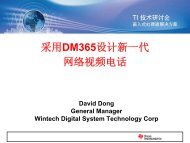
Mirror –10 deg<br />
Hinge<br />
Yoke<br />
Spring Tip<br />
Figure 3. Two DMD pixels<br />
the micromirrors. This results in a >90% fill factor and is one significant<br />
advantage of the DMD. The configuration of the array is flexible,<br />
depending on the application. DMD array sizes have been produced<br />
in the following configurations: 840 × 1 (first production DMD used<br />
for low-resolution printing), 640 × 480 (VGA resolution), 848 × 600<br />
(SVGA resolution), 1024 × 768 (XGA resolution), and<br />
1280 × 1024 (SXGA resolution), as well as demonstrations of other<br />
array sizes, such as, 7056 × 64 (high-resolution printing) and<br />
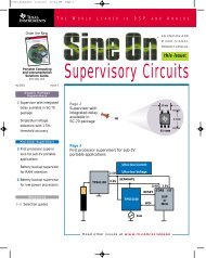
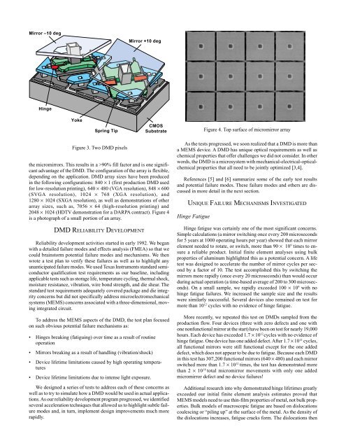
2048 × 1024 (HDTV demonstration for a DARPA contract). Figure 4<br />
is a photograph of a small portion of an array.<br />
DMD RELIABILITY DEVELOPMENT<br />
Mirror +10 deg<br />
Reliability development activities started in early 1992. We began<br />
with a detailed failure modes and effects analysis (FMEA) so that we<br />
could brainstorm potential failure modes and mechanisms. We then<br />
wrote a test plan to verify these failures as well as to highlight any<br />
unanticipated failure modes. We used <strong>Texas</strong> <strong>Instruments</strong> standard semiconductor<br />
qualification test requirements as our baseline, including<br />
applicable tests such as storage life, temperature cycling, thermal shock,<br />
moisture resistance, vibration, wire bond strength, and die shear. The<br />
standard test requirements adequately covered package and die integrity<br />
concerns but did not specifically address microelectromechanical<br />
systems (MEMS) concerns associated with a three-dimensional, moving<br />
integrated circuit.<br />
To address the MEMS aspects of the DMD, the test plan focused<br />
on such obvious potential failure mechanisms as:<br />
• Hinges breaking (fatiguing) over time as a result of routine<br />
operation<br />
• Mirrors breaking as a result of handling (vibration/shock)<br />
• Device lifetime limitations caused by high operating temperatures<br />
• Device lifetime limitations due to intense light exposure.<br />
CMOS<br />
Substrate<br />
We designed a series of tests to address each of these concerns as<br />
well as to try to simulate how a DMD would be used in actual applications.<br />
As our reliability development program progressed, we identified<br />
several acceleration techniques that allowed us to highlight subtle failure<br />
modes and, in turn, implement design improvements much more<br />
rapidly.<br />
As the tests progressed, we soon realized that a DMD is more than<br />
a MEMS device. A DMD has unique optical requirements as well as<br />
chemical properties that offer challenges we did not consider. In other<br />
words, the DMD is a microsystem with mechanical-electrical-opticalchemical<br />
properties that all need to be jointly optimized [3,4].<br />
References [5] and [6] summarize some of the early test results<br />
and potential failure modes. These failure modes and others are discussed<br />
in more detail in the next section.<br />
UNIQUE FAILURE MECHANISMS INVESTIGATED<br />
Hinge Fatigue<br />
Figure 4. Top surface of micromirror array<br />
Hinge fatigue was certainly one of the most significant concerns.<br />
Simple calculations (a mirror switching once every 200 microseconds<br />
for 5 years at 1000 operating hours per year) showed that each mirror<br />
element needed to rotate, or switch, more than 90 × 10 9 times to ensure<br />
a reliable product. Initial finite element analyses using bulk<br />
properties of aluminum highlighted this as a potential concern. A life<br />
test was designed to accelerate the number of mirror cycles per second<br />
by a factor of 10. The test accomplished this by switching the<br />
mirrors more rapidly (once every 20 microseconds) than would occur<br />
during actual operation (a time-based average of 200 to 300 microseconds).<br />
On a small sample, we rapidly exceeded 100 × 10 9 with no<br />
hinge fatigue failures. We increased the sample size and the results<br />
were similarly successful. Several devices also remained on test for<br />
more than 10 12 cycles with no evidence of hinge fatigue.<br />
More recently, we repeated this test on DMDs sampled from the<br />
production flow. Four devices (three with zero defects and one with<br />
one nonfunctional mirror at the start) have been on test for nearly 19,000<br />
hours. Each device has exceeded 1.7 × 10 12 cycles with no evidence of<br />
hinge fatigue. One device has one added defect. After 1.7 × 10 12 cycles,<br />
all functional mirrors were still functional except for the one added<br />
defect, which does not appear to be due to fatigue. Because each DMD<br />
in this test has 307,200 functional mirrors (640 × 480) and each mirror<br />
switched more than 1.7 × 10 12 times, the test has demonstrated more<br />
than 2 × 10 18 total micromirror movements with only one added<br />
micromirror defect and no device failures!<br />
Additional research into why demonstrated hinge lifetimes greatly<br />
exceeded our initial finite element analysis estimates proved that<br />
MEMS models need to use thin-film properties of metal, not bulk properties.<br />
Bulk models of macroscopic fatigue are based on dislocations<br />
coalescing or “piling up” at the surface of the metal. As the density of<br />
the dislocations increases, fatigue cracks form. The dislocations then