IEEE IRPS Douglass - Texas Instruments
IEEE IRPS Douglass - Texas Instruments
IEEE IRPS Douglass - Texas Instruments

You also want an ePaper? Increase the reach of your titles
YUMPU automatically turns print PDFs into web optimized ePapers that Google loves.
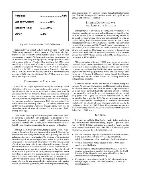
Particles |...............................68%<br />
Window Quality |.............18%<br />
Random Pixel |.........10%<br />
Other |...4%<br />
Figure 12. Pareto analysis of DMD field returns<br />
Occasionally we noticed a slight statistical trend toward some<br />
DMDs having more defects when exposed to UV and near-violet light.<br />
There were also several DMDs that failed because of stuck pixels in<br />
preproduction projectors. To better understand this phenomenon, we<br />
ran a series of tests using actual projectors. Each projector was modified<br />
to have a different UV cutoff filter. We found that DMDs were<br />
more likely to fail as a result of nonfunctional stuck pixels if exposed<br />
to light at wavelengths of 400 nm and below. A UV filter was, therefore,<br />
added to the DLP optics path to ensure a flux density of no more<br />
than 0.7 mW/cm 2 below 400 nm, most of which is beyond the visible<br />
spectrum of light. Since the addition of the UV filter, there have been<br />
no reported projector failures.<br />
ENVIRONMENTAL ROBUSTNESS<br />
One of the first steps we performed during the early stages of our<br />
reliability development program was to conduct a series of environmental<br />
tests similar to those performed in accordance with TI<br />
Semiconductor Group standards. These tests consisted of thermal<br />
shock, temperature cycling, moisture exposure, mechanical shock,<br />
vibration, acceleration, temperature storage, altitude, bond wire integrity,<br />
substrate attachment integrity, and ESD characterization. The<br />
superstructure was extremely robust [5]. The mirrors were not damaged<br />
by mechanical shock, vibration, or acceleration. There was no<br />
physical or parametric curve degradation due to temperature shock,<br />
cycling, or storage.<br />
These results, especially the robustness against vibration and shock,<br />
are surprising to some but easily explained. The micromirrors resonate<br />
at frequencies greater than 100 kHz. Normal handling occurs at<br />
frequencies less than 1000 Hz. Thus, the DMD micromirrors are unaffected<br />
by any vibration modes set up during assembly or handling.<br />
Although the mirrors were robust, the tests identified some weaknesses<br />
in the package that were subsequently corrected. The tests also<br />
demonstrated that loose particles in the package cavity can land on<br />
and damage the mirror superstructure. The evidence of mirror damage<br />
due to loose particles was the impetus to accelerate our particle reduction<br />
program to minimize our field reliability risk. The primary source<br />
of particles was found to be from the chemical interaction of the die<br />
attachment adhesive with the coating used to reduce surface adhesion.<br />
The secondary source was silicon particles, mostly from the edge of<br />
the die, and mostly due to the die sawing and separation process. Other<br />
miscellaneous particles (for example, carbon-based and aluminum)<br />
were found to come from handling, assembly, and equipment sources.<br />
Corrective actions to reduce our risk due to particles included the selection<br />
of a new die attachment adhesive, an improved wafer sawing<br />
process, better handling methods, more frequent particle monitoring,<br />
and numerous other process improvements throughout the fabrication<br />
line. Yield loss due to particles has been reduced by a significant percentage<br />
and continues to improve.<br />
LIFETIME DEMONSTRATIONS<br />
AND RELIABILITY ESTIMATES<br />
Through the use of accelerated life testing, the development of rudimentary<br />
models, and environmental qualification, we have identified<br />
what we believe to be the complete list of life-limiting factors. As<br />
discussed previously, hinge fatigue and environmental exposure are<br />
not life limiting. Particulate contamination appears to be random and<br />
not dependent on time or stress. We have not identified any correlation<br />
between light exposure and life. Through design robustness and process<br />
control, we have eliminated all known contributors to surface<br />
adhesion degradation. This leaves hinge memory. Because hinge<br />
memory is so predictable, we have easily estimated our lifetime to be<br />
greater than 100,000 hours, as long as the DMD die temperature is<br />
maintained at 45 °C or below.<br />
Although an actual lifetime of 100,000 hours has not yet been demonstrated,<br />
there is supporting evidence that DMD lifetime is measured<br />
in thousands of hours. Existing data through nearly 2 years of product<br />
deliveries have confirmed no DMD failures due to parametric curve<br />
degradation (bias voltage parametric curves and reset voltage parametric<br />
curves). Several DMDs remain on test through 19,000 actual<br />
operating hours with no failures to date. This certainly supports the<br />
test results and estimates.<br />
In terms of random failures, few devices have failed during enditem<br />
use. We anticipated that particles would dominate random failures,<br />
and that has proved to be true. Particles remain our primary cause of<br />
yield loss, but we have not observed a significant amount of customer<br />
returns caused by particles. In fact, even though particles are our primary<br />
pareto item (Figure 12), the field failure rate for all DMDs<br />
delivered to date is less than 0.2%. We have estimated a mean time<br />
between failures (MTBF) by using the total number of units shipped,<br />
multiplied by an estimate of usage hours per month, divided by the<br />
total number of reported DMD failures. Using conservative estimates<br />
for all three of these factors, we have a demonstrated MTBF (random<br />
failures) of 119,000 hours.<br />
SUMMARY<br />
This paper has highlighted DMD failure modes, failure mechanisms,<br />
and actions taken to improve reliability. Figure 13 presents a summary<br />
of DMD lifetime estimates as a result of major design<br />
enhancements implemented since 1992. The reliability development<br />
program has achieved the following milestones:<br />
• The DMD has been subjected to typical semiconductor environmental<br />
qualification tests and proved to be robust to all,<br />
including temperature cycling, mechanical shock, and vibration.<br />
• We have calculated an MTBF of greater than 119,000 hours<br />
based on actual field data.<br />
• We have projected a lifetime of more than 100,000 hours based<br />
on actual test results and modeling data developed for the DMD.<br />
The only life-limiting failure mechanism identified to date is<br />
temperature-accelerated hinge memory.<br />
• We have demonstrated more than 1.7 × 10¹² mirror cycles with<br />
no hinge fatigue failures. This correlates to 95,000 hours of<br />
normal operation.