CANDU Safety #12: Large Loss of Coolant Accident - Canteach
CANDU Safety #12: Large Loss of Coolant Accident - Canteach
CANDU Safety #12: Large Loss of Coolant Accident - Canteach

Create successful ePaper yourself
Turn your PDF publications into a flip-book with our unique Google optimized e-Paper software.
<strong>CANDU</strong> <strong>Safety</strong> <strong>#12</strong>:<br />
<strong>Large</strong> <strong>Loss</strong> <strong>of</strong> <strong>Coolant</strong> <strong>Accident</strong><br />
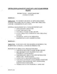
F. J. Doria<br />
Atomic Energy <strong>of</strong> Canada Limited<br />
24-May-01 <strong>CANDU</strong> <strong>Safety</strong> - <strong>#12</strong> - <strong>Large</strong> LOCA.ppt Rev. 0 1
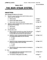
Overview<br />
λ Event sequence for a large break loss-<strong>of</strong> loss <strong>of</strong>-coolant coolant accident<br />
(LOCA)<br />
λ Acceptance criteria used to assess the results <strong>of</strong> the analysis<br />
λ Normal operating conditions<br />
λ Fuel and pressure tube behaviour during the transient<br />
λ Fission product release behaviour<br />
λ Containment behaviour<br />
24-May-01 <strong>CANDU</strong> <strong>Safety</strong> - <strong>#12</strong> - <strong>Large</strong> LOCA.ppt Rev. 0 2
<strong>Large</strong> LOCA with ECC Available<br />
λ Event Sequence<br />
– A large break occurs in a large diameter pipe in PHT,<br />
discharging coolant into containment<br />
– PHT depressurizes causing coolant voiding and an increase in<br />
reactivity<br />
– Reactor power increases until the reactor is shutdown on a<br />
neutronic trip (i.e., high power, high-rate high rate power) or process trip<br />
(i.e., low PHT pressure, low pressurizer level, high containment<br />
pressure etc.)<br />
– The PHT flow decreases fastest in the core pass downstream <strong>of</strong><br />
the break; and coolant stagnation occurs<br />
– Onset <strong>of</strong> fuel dryout results in an increase in fuel temperature<br />
– Once the PHT pressure is reduced to the ECC activation<br />
24-May-01 <strong>CANDU</strong> <strong>Safety</strong> - <strong>#12</strong> - <strong>Large</strong> LOCA.ppt Rev. 0 setpoint, ECC is activated; the two loops are isolated from each<br />
3
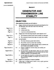
PHT Pumps<br />
Postulated<br />
Break Locations<br />
1) Pump Suction<br />
2) Inlet Header<br />
3) Outlet Header<br />
Primary Heat Transport System<br />
Steam Generators<br />
Feeders<br />
Reactor/Fuel Channels<br />
24-May-01 <strong>CANDU</strong> <strong>Safety</strong> - <strong>#12</strong> - <strong>Large</strong> LOCA.ppt Rev. 0 4
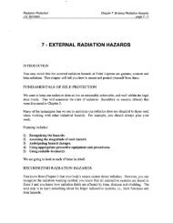
Break in Primary Heat Transport System<br />
λ Critical pass is the<br />
pass downstream <strong>of</strong><br />
the break location<br />
λ Key <strong>of</strong> analysis is to<br />
stagnate the flow in<br />
the channel<br />
the channel STEAM GENERATOR<br />
PRESSURIZER<br />
24-May-01 <strong>CANDU</strong> <strong>Safety</strong> - <strong>#12</strong> - <strong>Large</strong> LOCA.ppt Rev. 0 5<br />
ROH<br />
pressure gradient across<br />
one core pass reduced<br />
BREAK IN REACTOR<br />
INLET HEADER<br />
RIH<br />
REACTOR CORE<br />
RIH<br />
ROH<br />
PUMP<br />
OUTLET<br />
FEEDER<br />
PIPES<br />
INLET<br />
FEEDER<br />
PIPES<br />
PHTS.DWG
Analysis Acceptance Criteria<br />
λ Dose limits are not exceeded<br />
λ Two independent shutdown systems will arrest the reactivity<br />
and power excursion, and will maintain the reactor in a<br />
shutdown state<br />
λ Fuel channel integrity is not compromised<br />
λ The structural integrity <strong>of</strong> the containment must be maintained<br />
24-May-01 <strong>CANDU</strong> <strong>Safety</strong> - <strong>#12</strong> - <strong>Large</strong> LOCA.ppt Rev. 0 6
<strong>Large</strong> Break LOCA <strong>Safety</strong> Analysis<br />
λ Involves determining:<br />
– Fuel normal operating conditions<br />
– Fuel and fuel channel temperatures during LOCA transient<br />
– Fission product release during transient<br />
– Containment analysis<br />
– Dose analysis<br />
24-May-01 <strong>CANDU</strong> <strong>Safety</strong> - <strong>#12</strong> - <strong>Large</strong> LOCA.ppt Rev. 0 7
Fuel conditions prior to the onset <strong>of</strong> the accident<br />
– Normal operating conditions is modelled by the ELESTRES<br />
computer code<br />
– Main Input Requirements<br />
λ Fuel element (pellet and sheath) dimensions &<br />
properties<br />
λ Power/burnup history<br />
λ <strong>Coolant</strong> temperature and pressure<br />
– Important Output Parameters<br />
λ Fission product distribution (gap, grain boundary and<br />
grain bound)<br />
λ Internal gas pressure<br />
λ Fuel temperatures<br />
λ Pellet strain<br />
24-May-01 <strong>CANDU</strong> <strong>Safety</strong> - <strong>#12</strong> - <strong>Large</strong> LOCA.ppt Rev. 0 8
Transient Temperatures<br />
– Thermalhydraulic behaviour is calculated by the CATHENA<br />
circuit model<br />
λ Reactor Inlet Header Break (RIH)<br />
– 20%, 25%, 30%, 35%, 40% & 100%<br />
λ Pump Suction Pipe Break (PS)<br />
– 40%, 45%, 50%, 55%, 60%, 70% & 100%<br />
λ Reactor Outlet Header Break (ROH)<br />
– 80%, 90%, 95% & 100%<br />
– A critical break size is identified for each break location and<br />
a detailed CATHENA single-channel single channel analysis is performed:<br />
λ 35% RIH , 55% PS & 100% ROH<br />
24-May-01 <strong>CANDU</strong> <strong>Safety</strong> - <strong>#12</strong> - <strong>Large</strong> LOCA.ppt Rev. 0 9
Circuit Model <strong>of</strong> Primary Heat Transport System<br />
24-May-01 <strong>CANDU</strong> <strong>Safety</strong> - <strong>#12</strong> - <strong>Large</strong> LOCA.ppt Rev. 0 10
Depressurization in Inlet Headers (35% RIH<br />
Break)<br />
24-May-01 <strong>CANDU</strong> <strong>Safety</strong> - <strong>#12</strong> - <strong>Large</strong> LOCA.ppt Rev. 0 11
ECC Flows<br />
λ No ECC flow into the intact loop,<br />
since<br />
– intact loop pressure > broken loop pressure<br />
(intact loop was isolated from the broken<br />
loop)<br />
– Intact loop pressure > ECC supply pressure<br />
λ LOCA signal & loop isolation<br />
initiated at 9 s after accident<br />
λ Loop isolation complete by 29 s<br />
λ ECC flows into the broken loop, 3<br />
stages<br />
– High-pressure High pressure injection initiation (38 s)<br />
– Medium-pressure Medium pressure injection (293 s)<br />
– Low-pressure Low pressure injection (678 s)<br />
24-May-01 <strong>CANDU</strong> <strong>Safety</strong> - <strong>#12</strong> - <strong>Large</strong> LOCA.ppt Rev. 0 12
Break Survey for RIH breaks (Flows)<br />
CATHENA Circuit Model<br />
λ large breaks ==><br />
sustained reverse flow<br />
λ small breaks ==><br />
forward flow<br />
λ medium breaks ==><br />
stagnation<br />
λ Critical break is 35%<br />
RIH<br />
Flow (kg/s)<br />
200<br />
100<br />
0<br />
-100<br />
-200<br />
-300<br />
-400<br />
-500<br />
<strong>Coolant</strong> Flow at Center <strong>of</strong> Downstream Core Pass (RIH)<br />
0 10 20 30 40 50<br />
Time (s)<br />
EARLY FLOW STAGNATION<br />
20% RIH 25% RIH 30% RIH<br />
35% RIH 40% RIH 100% RIH<br />
24-May-01 <strong>CANDU</strong> <strong>Safety</strong> - <strong>#12</strong> - <strong>Large</strong> LOCA.ppt Rev. 0 13
Break Survey for RIH breaks (Sheath<br />
Temperature)<br />
CATHENA Circuit Model<br />
λ Temperature transient<br />
corresponds to flow<br />
conditions<br />
λ Flow stagnation ==><br />
temperatures increase<br />
λ Break in flow<br />
stagnation ==><br />
temperatures drop<br />
λ Critical break is 35%<br />
RIH<br />
Temperature ( o C)<br />
RIH Break Survey- Outside Sheath Temperature at Bundle 7<br />
(center channel) <strong>of</strong> Critical Core Pass<br />
1200<br />
1000<br />
800<br />
600<br />
400<br />
200<br />
0<br />
0 20 40 60 80 100<br />
Time (s)<br />
24-May-01 <strong>CANDU</strong> <strong>Safety</strong> - <strong>#12</strong> - <strong>Large</strong> LOCA.ppt Rev. 0 14<br />
20% RIH<br />
25% RIH<br />
30% RIH<br />
35% RIH<br />
40% RIH<br />
100% RIH
Single Channel Model for 35% RIH Critical Break<br />
Boundary Conditions from Circuit Analysis Applied<br />
λ Header boundary<br />
conditions (pressure,<br />
enthalpy, void)<br />
λ 6 inlet feeder<br />
segments<br />
λ Inlet end-fitting end fitting<br />
model<br />
λ 12 channel segments<br />
(for 12 bundles)<br />
λ Outlet end-fitting end fitting<br />
model<br />
λ 7 outlet feeder<br />
segments<br />
Inlet header Outlet header<br />
Inlet Feeder<br />
Outlet Feeder<br />
Inlet End-fitting Fuel Channel Outlet End-fitting<br />
24-May-01 <strong>CANDU</strong> <strong>Safety</strong> - <strong>#12</strong> - <strong>Large</strong> LOCA.ppt Rev. 0 15
Temperature ( o C)<br />
Single Channel Analysis <strong>of</strong> 35% RIH Critical<br />
Break<br />
Channel 06 (7.3 MW); Outer Elements; Sheath Temperatures<br />
1400<br />
1200<br />
1000<br />
800<br />
600<br />
400<br />
200<br />
0<br />
Critical Pass (Broken Loop)<br />
0 50 100 150 200<br />
Time (s)<br />
Bundle 5 Bundle 6 Bundle 7 Bundle 8<br />
Non-Critical Pass (Broken Loop)<br />
24-May-01 <strong>CANDU</strong> <strong>Safety</strong> - <strong>#12</strong> - <strong>Large</strong> LOCA.ppt Rev. 0 16<br />
Temperature ( o C)<br />
1400<br />
1200<br />
1000<br />
800<br />
600<br />
400<br />
200<br />
0<br />
0 50 100 150 200<br />
Time (s)<br />
Bundle 5 Bundle 6 Bundle 7 Bundle 8
Detailed Fuel Element Analysis<br />
λ Objective <strong>of</strong> analysis is to predict the potential for sheath<br />
failure during the LOCA<br />
λ Boundary conditions from single-channel single channel CATHENA analysis<br />
is provided to ELOCA code<br />
– coolant temperature,<br />
– coolant pressure,<br />
– sheath-to sheath to-coolant coolant heat transfer coefficient,<br />
– ELESTRES normal operating conditions, and<br />
– power pulse<br />
λ For excessive straining: the increase in sheath temperature<br />
and high internal gas pressure in conjunction with low coolant<br />
pressure may result in sheath failure<br />
24-May-01 <strong>CANDU</strong> <strong>Safety</strong> - <strong>#12</strong> - <strong>Large</strong> LOCA.ppt Rev. 0 17
Fuel Element Failure Mechanisms<br />
λ The ELOCA code is used to generate a sheath failure map<br />
(threshold map) in conjunction with failure criteria, for<br />
• no<br />
example<br />
no excessive example<br />
straining- straining 5% strain less than 1000 oC • no-oxide no oxide cracking- cracking 2% strain greater than 1000 oC • no beryllium-braze beryllium braze penetration<br />
• no oxygen embrittlement<br />
• no fuel melting<br />
24-May-01 <strong>CANDU</strong> <strong>Safety</strong> - <strong>#12</strong> - <strong>Large</strong> LOCA.ppt Rev. 0 18
Detailed Fuel Analysis by ELOCA code<br />
λ Sheath temperatures for a 30% RIH LOCA scenario<br />
λ Outer elements <strong>of</strong> bundle position 6<br />
λ High-powered High powered Channel O6 (7.3 MW)<br />
EARLY FLOW STAGNATION<br />
BREAK IN FLOW STAGNATION<br />
24-May-01 <strong>CANDU</strong> <strong>Safety</strong> - <strong>#12</strong> - <strong>Large</strong> LOCA.ppt Rev. 0 19
Pressure Tube Behaviour<br />
λ Pressure tube deformation is expected for LOCA breaks<br />
resulting in high pressure tube temperatures at high channel<br />
pressures<br />
λ Objective <strong>of</strong> analysis is to determine pressure tube<br />
temperature at time <strong>of</strong> contact with its surrounding calandria<br />
tube<br />
λ Moderator temperatures are sufficiently low enough to prevent<br />
film boiling (dryout) on the outer surface <strong>of</strong> the calandria tube<br />
after the pressure tube-calandria tube calandria tube contact<br />
λ Localized hotspots on the pressure tube due to bearing-<br />
pad/pressure tube contact results in localized deformation <strong>of</strong><br />
tube<br />
λ 24-May-01 No channel failures <strong>CANDU</strong> during <strong>Safety</strong> - a <strong>#12</strong> large - <strong>Large</strong> LOCA.ppt break Rev. 0 LOCA<br />
20
Temperature ( o C)<br />
1000<br />
900<br />
800<br />
700<br />
600<br />
500<br />
400<br />
300<br />
200<br />
100<br />
0<br />
Pressure Tube Temperatures<br />
Critical breaks: Pressure Tube Temperature<br />
at Bundle 7 <strong>of</strong> 7.3 MW Channel<br />
55% Pump<br />
Suction 100% Reactor<br />
35% Reactor Outlet Header<br />
Inlet Header<br />
0 10 20 30 40 50 60<br />
Time (s)<br />
24-May-01 <strong>CANDU</strong> <strong>Safety</strong> - <strong>#12</strong> - <strong>Large</strong> LOCA.ppt Rev. 0 21
Barriers to Fission Product Release<br />
1) Uranium-Dioxide Fuel Matrix & 2) Sheath<br />
3) Primary Heat Transport System, 4) Containment & 5) Boundary<br />
24-May-01 <strong>CANDU</strong> <strong>Safety</strong> - <strong>#12</strong> - <strong>Large</strong> LOCA.ppt Rev. 0 22
Fission Product Release<br />
λ The gap inventory plays a key role in the fission products released released<br />
during the transient (i.e., sheath failure ==> retention & transport transport<br />
<strong>of</strong><br />
fission products in the gap ==> released to heat transport system) system)<br />
λ Secondary release phenomena may include diffusion, fuel<br />
oxidation, Zircaloy-UO<br />
Zircaloy UO2 reaction and fuel cracking<br />
λ LOCA Methodology<br />
– Entire gap inventory is assumed to be released upon sheath failure failure<br />
– 1% <strong>of</strong> fission products residing on grains and grain boundary is assumed to<br />
be released: to account for the possibility <strong>of</strong> secondary release mechanisms<br />
λ Fission Product Retention in Heat Transport System<br />
– large surface area in primary heat transport system (for example, example,<br />
endfitting,<br />
feeders) for fission product deposition<br />
– The retention <strong>of</strong> fission products in the system are currently not not<br />
credited in<br />
the analysis; however, plan to credit in the future<br />
24-May-01 <strong>CANDU</strong> <strong>Safety</strong> - <strong>#12</strong> - <strong>Large</strong> LOCA.ppt Rev. 0 23
Example <strong>of</strong> Fission Product Release Transient<br />
I-131 Release (TBq)<br />
2500<br />
2000<br />
1500<br />
1000<br />
500<br />
0<br />
Transient I-131 Release for 50%<br />
Pump Suction Break<br />
0 20 40 60 80<br />
Time (s)<br />
24-May-01 <strong>CANDU</strong> <strong>Safety</strong> - <strong>#12</strong> - <strong>Large</strong> LOCA.ppt Rev. 0 24
Pressure (kPa(g))<br />
Containment Behaviour<br />
λ Pressure increases rapidly due to large amount <strong>of</strong> heat<br />
rejected to the containment atmosphere<br />
λ Peak Pressure is below design pressure <strong>of</strong> 124 kPa (g)<br />
λ Dousing system limits peak pressure<br />
Containment Pressure Transient for<br />
100% ROH LOCA<br />
100<br />
80<br />
60<br />
40<br />
20<br />
0<br />
0 100 200 300 400 500<br />
Time (s)<br />
24-May-01 <strong>CANDU</strong> <strong>Safety</strong> - <strong>#12</strong> - <strong>Large</strong> LOCA.ppt Rev. 0 25