LM741 1 2 2 3 3 4 8 7 7 +15 V 15 V 4 6 6out 5 + - Indiana University
LM741 1 2 2 3 3 4 8 7 7 +15 V 15 V 4 6 6out 5 + - Indiana University
LM741 1 2 2 3 3 4 8 7 7 +15 V 15 V 4 6 6out 5 + - Indiana University

Create successful ePaper yourself
Turn your PDF publications into a flip-book with our unique Google optimized e-Paper software.
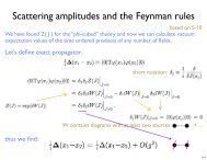
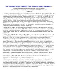
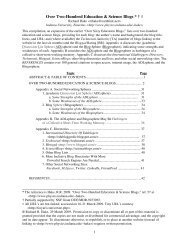
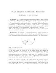
(a) Photodiode: Use the supplied phototransistor (feel free to peel back some of<br />
the rubber coating if not enough light is getting into the fiber optic lead) as a photodiode<br />
in the circuit above. To determine the pins, try using the DVM to distinguish them as<br />
learned previously. Examine the output signal (if the DC level is more than 10 V, reduce<br />
the feedback resistor to 1 MΩ).<br />
If you see fuzz on the output (oscillations), put a small capacitor (~100 pF) in<br />
parallel with the feedback resistor.<br />
What is the average DC output level, and what is the percentage "modulation"?<br />
This can be quite large due to the fluorescent lights in the lab... What input photocurrent<br />
does the output level correspond to? Try covering the phototransistor with your hand.<br />
Look at the "summing junction" (the inverting input pin) with the scope, as the output<br />
voltage varies. What should you see?<br />
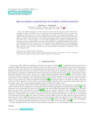
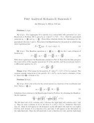
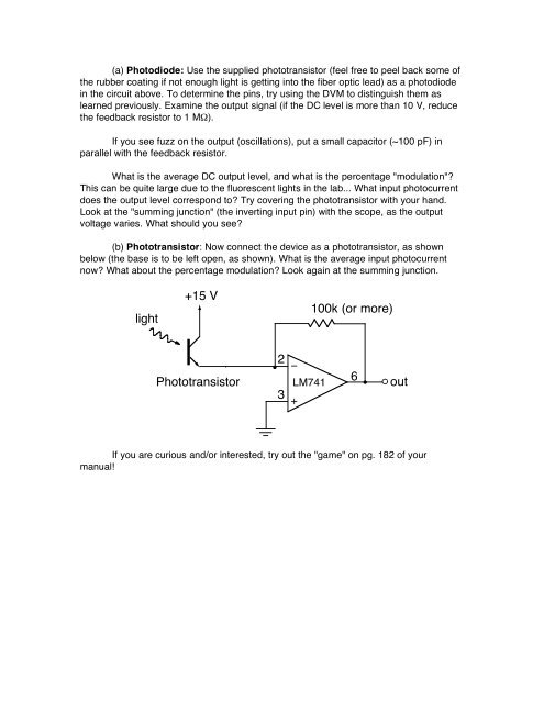
(b) Phototransistor: Now connect the device as a phototransistor, as shown<br />
below (the base is to be left open, as shown). What is the average input photocurrent<br />
now? What about the percentage modulation? Look again at the summing junction.<br />
light<br />
<strong>+<strong>15</strong></strong> V<br />
Phototransistor<br />
2<br />
<strong>LM741</strong><br />
3<br />
+<br />
100k (or more)<br />
If you are curious and/or interested, try out the "game" on pg. 182 of your<br />
manual!<br />
!<br />
6<br />
out