Lab #1: Electrical Measurements I
Lab #1: Electrical Measurements I
Lab #1: Electrical Measurements I

You also want an ePaper? Increase the reach of your titles
YUMPU automatically turns print PDFs into web optimized ePapers that Google loves.
Indiana U, Physics Dept (H.O. Meyer 7/06)<br />
<strong>Lab</strong> <strong>#1</strong>: <strong>Electrical</strong> <strong>Measurements</strong> I<br />
Goal: Learn to measure electrical quantities; investigate the properties of electrical<br />
meters, batteries and power supplies.<br />
Equipment: Batteries (dry cells), digital multi-meters (DMM), assorted resistors and<br />
variable resistor bank, regulated DC power supplies.<br />
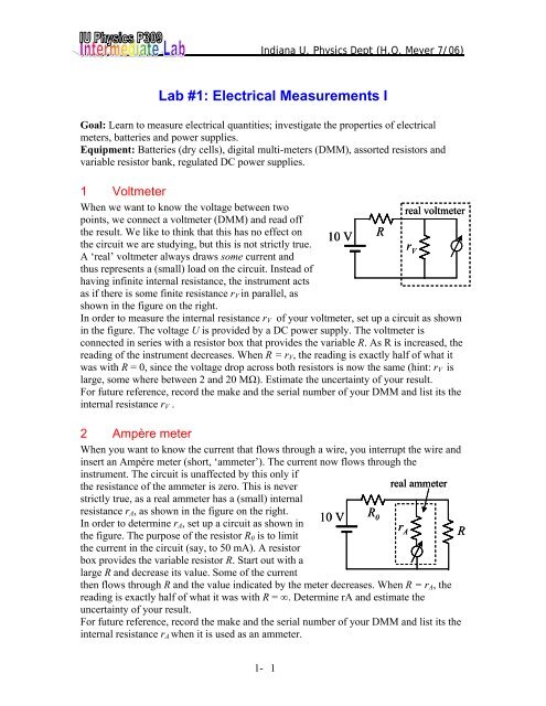
1 Voltmeter<br />
When we want to know the voltage between two<br />
points, we connect a voltmeter (DMM) and read off<br />
real voltmeter<br />
the result. We like to think that this has no effect on<br />
the circuit we are studying, but this is not strictly true.<br />
A ‘real’ voltmeter always draws some current and<br />
thus represents a (small) load on the circuit. Instead of<br />
having infinite internal resistance, the instrument acts<br />
as if there is some finite resistance rV in parallel, as<br />
shown in the figure on the right.<br />
10 V<br />
R<br />
r V<br />
In order to measure the internal resistance rV of your voltmeter, set up a circuit as shown<br />
in the figure. The voltage U is provided by a DC power supply. The voltmeter is<br />
connected in series with a resistor box that provides the variable R. As R is increased, the<br />
reading of the instrument decreases. When R = rV, the reading is exactly half of what it<br />
was with R = 0, since the voltage drop across both resistors is now the same (hint: rV is<br />
large, some where between 2 and 20 MΩ). Estimate the uncertainty of your result.<br />
For future reference, record the make and the serial number of your DMM and list its the<br />
internal resistance rV .<br />
2 Ampère meter<br />
When you want to know the current that flows through a wire, you interrupt the wire and<br />
insert an Ampère meter (short, ‘ammeter’). The current now flows through the<br />
instrument. The circuit is unaffected by this only if<br />
the resistance of the ammeter is zero. This is never<br />
strictly true, as a real ammeter has a (small) internal<br />
resistance rA, as shown in the figure on the right.<br />
In order to determine rA, set up a circuit as shown in<br />
the figure. The purpose of the resistor R0 is to limit<br />
the current in the circuit (say, to 50 mA). A resistor<br />
box provides the variable resistor R. Start out with a<br />
large R and decrease its value. Some of the current<br />
then flows through R and the value indicated by the meter decreases. When R = rA, the<br />
reading is exactly half of what it was with R = ∞. Determine rA and estimate the<br />
uncertainty of your result.<br />
For future reference, record the make and the serial number of your DMM and list its the<br />
internal resistance rA when it is used as an ammeter.<br />
1- 1<br />
10 V<br />
R 0<br />
real ammeter<br />
r A<br />
R
3 Voltage source (battery)<br />
A battery is a device that produces a voltage difference between its poles. When a ‘load’<br />
resistor R is connected between these poles, a current I flows. As we make R smaller, the<br />
current cannot grow indefinitely, and the voltage V across<br />
the battery drops. That is, the battery behaves as if there<br />
is an ‘output resistance’ rS inside the battery that limits<br />
the current flow.<br />
In order to measure rS, connect a variable load R (resistor<br />
box) and a voltmeter across the battery as shown in the<br />
figure on the right. In addition, insert a second DMM as a<br />
current meter in the circuit to measure the current I<br />
through the load resistor. If R is very large, I = 0 and<br />
V=u0.<br />
Start at a large load R (kΩ) and work your way down until I has become a few mA.<br />
Continue till you draw about 50 mA. Be aware that a small R means a large current,<br />
which alters the battery irreversibly. Be reluctant to apply small loads and if you do, only<br />
for the duration of the reading.<br />
Assuming that the ammeter has no internal resistance and the internal resistance of the<br />
voltmeter is infinite, show that<br />
1 1 ⎛ ⎞<br />
= ⎜ + 1⎟<br />
⎝ ⎠ R<br />
rS<br />
(1)<br />
V u<br />
0<br />
Plot 1/V versus 1/R, and determine rS from a straight-line fit to your data. Estimate the<br />
error.<br />
Discuss if and how the internal resistances rV and rA of the voltmeter and the ammeter<br />
affect your measurement.<br />
4 Voltage source (regulated power supply)<br />
A regulated power supply is constructed to keep the voltage constant. In other words, its<br />
internal resistance is much smaller than that of a battery. Thus, as we lower the load<br />
resistance R, the voltage V changes only very little. Lowering R too much blows the fuse<br />
of the supply.<br />
To measure a small change of a voltage, it is better to<br />
measure not relative to ground, but relative to a fixed<br />
‘reference’ voltage that is of the size of u0. One then can use<br />
the DMM on a more sensitive scale, to observe small changes<br />
of V.<br />
A useful method to generate a reference voltage is to use any<br />
DC power supply followed by a ‘voltage divider’. A voltage<br />
divider (see figure on the right) consists of two (or more)<br />
resistors in series. The input voltage, Vin, is applied across the<br />
complete resistor chain. A tap between the resistors in the<br />
chain provides an output voltage Vout that is a fixed fraction of<br />
the input voltage.<br />
1- 2<br />
real voltage<br />
source<br />
r S<br />
u 0<br />
I<br />
R<br />
V
Construct such a voltage divider by connecting R1 = 10 kΩ and R2 = 4.7 kΩ in series<br />
across the +15V power supply of your workstation. The voltage Vout across R2 now<br />
represents a (divided) ‘power supply’ and can be used as a reference.<br />
5 Output Resistance of a Voltage Divider (optional)<br />
The voltage Vout across R2 of the voltage divider you have constructed in sect.4 represents<br />
a (divided) ‘power supply’. Find the output resistance rS of this ‘power supply’.<br />
Connect a load resistor R across R2. Measure the voltages across resistor R (or R2) and the<br />
current through the load resistor for R = 3.3, 6.8, 10, 33, 100 kΩ, and ∞. Show<br />
analytically that rS equal the resistance of R1 and R2 in parallel. Compare the result to the<br />
measurements of the +5V power supply of your workstation, and discuss the result.<br />
6 Summary<br />
List the values for the internal resistances that you have measured in a summary table.<br />
These are typical values that represent the departure of real from ideal devices that you<br />
may memorize for future reference.<br />
1- 3